Day 2 Frame Relay Configuration and Troubleshooting
CCNA 640-802 Exam Topics
![]() Configure and verify Frame Relay on Cisco routers.
Configure and verify Frame Relay on Cisco routers.
![]() Troubleshoot WAN implementation issues.
Troubleshoot WAN implementation issues.
Key Topics
Today we finish our review of CCNA exam topics with a look at Frame Relay and basic WAN troubleshooting. Frame Relay is currently the most popular choice for WAN implementations. Therefore, you must have a basic understanding of Frame Relay, including its conceptual framework, configuration, and verification. As a final topic, we review various WAN errors and their potential causes.
Frame Relay Concepts
Frame Relay is a connection-oriented data-link technology that is streamlined to provide high performance and efficiency. For error protection, it relies on upper-layer protocols and dependable fiber and digital networks.
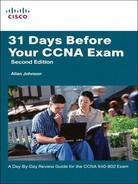
Frame Relay defines the interconnection process between the router and the local Frame Relay of the service provider, as shown in Figure 2-1.
Devices attached to a Frame Relay WAN fall into the following two categories:
![]() Data terminal equipment (DTE):Examples of DTE devices are Frame Relay Access Devices (FRAD), routers, and bridges.
Data terminal equipment (DTE):Examples of DTE devices are Frame Relay Access Devices (FRAD), routers, and bridges.
![]() Data communications equipment (DCE):In most cases, the switches in a WAN are Frame Relay switches.
Data communications equipment (DCE):In most cases, the switches in a WAN are Frame Relay switches.
Frame Relay Components
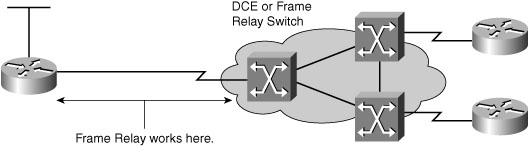
Frame Relay provides a means for statistically multiplexing many logical data conversations, referred to as virtual circuits (VC), over a single physical transmission link by assigning connection identifiers to each pair of DTE devices. The service provider switching equipment constructs a switching table that maps the connection identifier to outbound ports. When a frame is received, the switching device analyzes the connection identifier and delivers the frame to the associated outbound port. The complete path to the destination is established prior to the transmission of the first frame. Figure 2-2 illustrates a Frame Relay connection and identifies the many components within Frame Relay.
The following terms are used frequently in Frame Relay discussions:
![]() Local access rate:The rate at which data travels into or out of the network, regardless of other settings.
Local access rate:The rate at which data travels into or out of the network, regardless of other settings.
![]() Virtual circuit (VC):Logical circuit, uniquely identified by a data-link connection identifier (DLCI), that is created to ensure bidirectional communication from one DTE device to another.
Virtual circuit (VC):Logical circuit, uniquely identified by a data-link connection identifier (DLCI), that is created to ensure bidirectional communication from one DTE device to another.
![]() Permanent virtual circuit (PVC):Provides permanently established connections that are used for frequent and consistent data transfers.
Permanent virtual circuit (PVC):Provides permanently established connections that are used for frequent and consistent data transfers.
![]() Switched virtual circuit (SVC):Provides temporary connections that are used in situations that require only sporadic data transfer between DTE devices across the Frame Relay network.
Switched virtual circuit (SVC):Provides temporary connections that are used in situations that require only sporadic data transfer between DTE devices across the Frame Relay network.
![]() Data-link connection identifier (DLCI):Contains a 10-bit number in the address field of the Frame Relay frame header that identifies the VC. DLCIs have local significance because the identifier references the point between the local router and the local Frame Relay switch to which the DLCI is connected. Therefore, devices at opposite ends of a connection can use different DLCI values to refer to the same virtual connection.
Data-link connection identifier (DLCI):Contains a 10-bit number in the address field of the Frame Relay frame header that identifies the VC. DLCIs have local significance because the identifier references the point between the local router and the local Frame Relay switch to which the DLCI is connected. Therefore, devices at opposite ends of a connection can use different DLCI values to refer to the same virtual connection.
As shown in Figure 2-2, Router A has two virtual circuits that are configured on one physical interface. A DLCI of 100 identifies the VC that connects to Router B. A DLCI of 400 identifies the VC that connects to Router C. At the other end, a different DLCI number can be used to identify the VC.
![]() Committed information rate (CIR):When subscribing to a Frame Relay service, you specify the CIR, which is the local access rate—for example, 56 kbps or T1. Typically, you are also asked to specify a CIR for each DLCI. If you send information faster than the CIR on a given DLCI, the network flags some frames with a discard eligible (DE) bit.
Committed information rate (CIR):When subscribing to a Frame Relay service, you specify the CIR, which is the local access rate—for example, 56 kbps or T1. Typically, you are also asked to specify a CIR for each DLCI. If you send information faster than the CIR on a given DLCI, the network flags some frames with a discard eligible (DE) bit.
![]() Inverse Address Resolution Protocol (ARP):A method of dynamically associating the network layer address of the remote router with a local DLCI.
Inverse Address Resolution Protocol (ARP):A method of dynamically associating the network layer address of the remote router with a local DLCI.
![]() Local Management Interface (LMI):A signaling standard between the router (DTE device) and the local Frame Relay switch (DCE device) that is responsible for managing the connection and maintaining status between the router and the Frame Relay switch.
Local Management Interface (LMI):A signaling standard between the router (DTE device) and the local Frame Relay switch (DCE device) that is responsible for managing the connection and maintaining status between the router and the Frame Relay switch.
![]() Forward explicit congestion notification (FECN):A bit in the address field of the Frame Relay frame header. If the network is congested, DCE devices (Frame Relay switches) set the FECN bit value of the frames to 1 to signal downstream DTE devices that flow control might be warranted.
Forward explicit congestion notification (FECN):A bit in the address field of the Frame Relay frame header. If the network is congested, DCE devices (Frame Relay switches) set the FECN bit value of the frames to 1 to signal downstream DTE devices that flow control might be warranted.
![]() Backward explicit congestion notification (BECN):A bit in the address field of the Frame Relay frame header. Operates like the FECN bit but travels in the opposite direction, informing upstream DTE devices that congestion is occurring and that flow control might be warranted.
Backward explicit congestion notification (BECN):A bit in the address field of the Frame Relay frame header. Operates like the FECN bit but travels in the opposite direction, informing upstream DTE devices that congestion is occurring and that flow control might be warranted.
Frame Relay Topologies
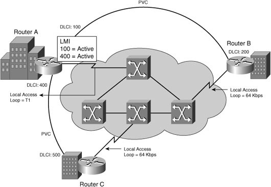
Frame Relay allows you to interconnect your remote sites in a variety of topologies.
Figure 2-3 illustrates these topologies, which are described in the list that follows.
![]() Partial-mesh topology:Not all sites have direct access to all other sites.
Partial-mesh topology:Not all sites have direct access to all other sites.
![]() Full-mesh topology:All routers have VCs to all other destinations. Use the n (n – 1) / 2 formula to calculate the total number of links that are required to implement a full-mesh topology, where n is the number of end points (nodes).
Full-mesh topology:All routers have VCs to all other destinations. Use the n (n – 1) / 2 formula to calculate the total number of links that are required to implement a full-mesh topology, where n is the number of end points (nodes).
![]() Star topology:The star topology, also known as a hub-and-spoke configuration, is the least expensive topology because it requires the least number of PVCs.
Star topology:The star topology, also known as a hub-and-spoke configuration, is the least expensive topology because it requires the least number of PVCs.
NBMA Limitations and Solutions
By default, a Frame Relay network provides nonbroadcast multiaccess (NBMA) connectivity between remote sites. An NBMA environment is treated like other broadcast media environments, such as Ethernet, where all the routers are on the same subnet.
However, to reduce cost, NBMA clouds are usually built in a hub-and-spoke topology. With a hub-and-spoke topology, the physical topology does not provide the multiaccess capabilities that Ethernet does, so each router might not have separate PVCs to reach the other remote routers on the same subnet. Split horizon is one of the main issues you encounter when Frame Relay is running multiple PVCs over a single interface.
In any Frame Relay topology, when a single interface must be used to interconnect multiple sites, you can have reachability issues because of the NBMA nature of Frame Relay. The Frame Relay NBMA topology can cause the following two problems:
![]() Routing update reachability:Split horizon prevents a routing update that is received on an interface from being forwarded out the same interface. So a hub router will not send updates from one spoke router to another spoke router if the update must go out the same interface (Split horizon applies only to distance vector routing protocols).
Routing update reachability:Split horizon prevents a routing update that is received on an interface from being forwarded out the same interface. So a hub router will not send updates from one spoke router to another spoke router if the update must go out the same interface (Split horizon applies only to distance vector routing protocols).
![]() Broadcast replication:With routers that support multipoint connections over a single interface that terminate many PVCs, the router must replicate broadcast packets, such as routing update broadcasts, on each PVC to the remote routers. These replicated broadcast packets consume bandwidth and cause significant latency variations in user traffic.
Broadcast replication:With routers that support multipoint connections over a single interface that terminate many PVCs, the router must replicate broadcast packets, such as routing update broadcasts, on each PVC to the remote routers. These replicated broadcast packets consume bandwidth and cause significant latency variations in user traffic.
The following methods exist to solve the routing update reachability issue:
![]() Turn off split horizon; however, disabling split horizon increases the chances of routing loops in your network. (Split horizon is not an issue if you use a link-state routing protocol.)
Turn off split horizon; however, disabling split horizon increases the chances of routing loops in your network. (Split horizon is not an issue if you use a link-state routing protocol.)
![]() Use a fully meshed topology; however, this topology increases the cost.
Use a fully meshed topology; however, this topology increases the cost.
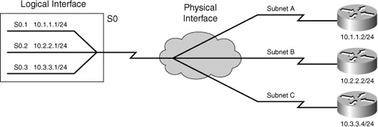
![]() Use subinterfaces. When you use a Frame Relay point-to-point subinterface, each subinterface is on its own subnet.
Use subinterfaces. When you use a Frame Relay point-to-point subinterface, each subinterface is on its own subnet.
Figure 2-4 shows how to resolve the issues using subinterfaces.
Inverse ARP and LMI Concepts
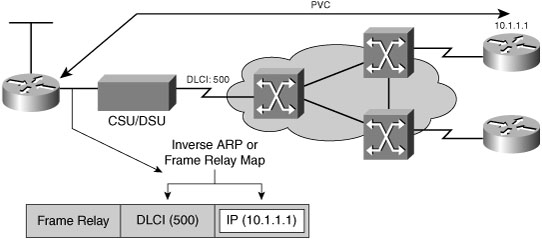
Routers can automatically discover their local DLCI from the local Frame Relay switch using the LMI protocol. Then the local DLCI can be dynamically mapped to the remote router network layer addresses with Inverse ARP.
As shown in Figure 2-5, using Inverse ARP, the router on the left can automatically discover the remote router IP address and then map it to the local DLCI. In this case, the local DLCI of 500 is mapped to the 10.1.1.1 IP address.
Frame Relay signaling is required between the router and the Frame Relay switch. Figure 2-6 shows how the signaling is used to get information about the different DLCIs.

The LMI is a signaling standard between the router and the Frame Relay switch. The LMI is responsible for managing the connection and maintaining the status between the devices.
Although the LMI is configurable, beginning in Cisco IOS Release 11.2, the Cisco router tries to autosense which LMI type the Frame Relay switch is using. The router sends one or more full LMI status requests to the Frame Relay switch. The Frame Relay switch responds with one or more LMI types, and the router configures itself with the last LMI type received. Cisco routers support the following three LMI types: Cisco, ANSI, and Q 933A.
When the router receives LMI information, it updates its VC status to one of the following three states:
![]() Active:Indicates that the VC connection is active and that routers can exchange data over the Frame Relay network.
Active:Indicates that the VC connection is active and that routers can exchange data over the Frame Relay network.
![]() Inactive:Indicates that the local connection to the Frame Relay switch is working, but the remote router connection to the remote Frame Relay switch is not working.
Inactive:Indicates that the local connection to the Frame Relay switch is working, but the remote router connection to the remote Frame Relay switch is not working.
![]() Deleted:Indicates that either no LMI is being received from the Frame Relay switch or no service exists between the router and local Frame Relay switch.
Deleted:Indicates that either no LMI is being received from the Frame Relay switch or no service exists between the router and local Frame Relay switch.
Inverse ARP and LMI Operation
The following is a summary of how Inverse ARP and LMI signaling work with a Frame Relay connection:
-
Each router connects to the Frame Relay switch through a channel service unit/data service unit (CSU/DSU).
-
When Frame Relay is configured on an interface, the router sends an LMI status inquiry message to the Frame Relay switch. The message notifies the switch of the router status and asks the switch for the connection status of the router VCs.
-
When the Frame Relay switch receives the request, it responds with an LMI status message that includes the local DLCIs of the PVCs to the remote routers to which the local router can send data.
-
For each active DLCI, each router sends an Inverse ARP packet to introduce itself.
Figure 2-7 illustrates the first four steps of this process.
-
When a router receives an Inverse ARP message, it creates a map entry in its Frame Relay map table that includes the local DLCI and the remote router network layer address.
-
Every 60 seconds, routers send Inverse ARP messages on all active DLCIs. Every 10 seconds, the router exchanges LMI information with the switch (keepalives).
-
The router changes the status of each DLCI to active, inactive, or deleted, based on the LMI response from the Frame Relay switch.
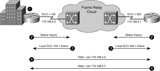
Figure 2-8 illustrates Steps 5–7 of this process.

Configuring and Verifying Frame Relay
The following list summarizes the Frame Relay configuration steps.
Step 1 Configure the physical interface to use Frame Relay encapsulation (encapsulation frame-relay interface subcommand).
Step 2 Configure an IP address on the interface or subinterface (ip address subcommand).
Step 3 (Optional) Manually set the LMI type on each physical serial interface (frame-relay lmi-type interface subcommand).
Step 4 (Optional) Change from the default encapsulation of cisco to ietf by doing the following:
a. For all VCs on the interface, add the ietf keyword to the encapsulation frame-relay interface subcommand.
b. For a single VC, add the ietf keyword to the frame-relay interface dlci interface subcommand (point-to-point subinterfaces only) or to the frame-relay map command.
Step 5 (Optional) If you aren’t using the (default) Inverse ARP to map the DLCI to the next-hop router’s IP address, define static mapping using the frame-relay map ip dlci ip-address broadcast subinterface subcommand.
Step 6 On subinterfaces, associate one (point-to-point) or more (multipoint) DLCIs with the subinterface in one of two ways:
a. Using the frame-relay interface-dlci dlci subinterface subcommand
b. As a side effect of static mapping using the frame-relay map ip dlci ip-address broadcast subinterface subcommand
Full Mesh with One Subnet
The first example shows the briefest possible Frame Relay configuration—one that uses just the first two steps of the configuration checklist in this chapter. For the topology shown in Figure 2-9, configure a full mesh Frame Relay network using subnet 10.1.1.0/24. Use default settings for LMI, Inverse ARP, and encapsulation. Examples 2-1, 2-2, and 2-3 show the full configuration using EIGRP as the routing protocol.

Example 2-1 Frame Relay Full Mesh with One Subnet: R1
R1(config)#interface serial 0/0/0
R1(config-if)#encapsulation frame-relay
R1(config-if)#ip address 10.1.1.1 255.255.255.0
R1(config-if)#no shutdown
R1(config-if)#interface fastethernet 0/0
R1(config-if)#ip address 192.168.10.1 255.255.255.0
R1(config-if)#no shutdown
R1(config-if)#router eigrp 1
R1(config-router)#network 10.0.0.0
R1(config-router)#network 192.168.10.0
Example 2-3 Frame Relay Full Mesh with One Subnet: R2
R3(config)#interface serial 0/0/0
R3(config-if)#encapsulation frame-relay
R3(config-if)#ip address 10.1.1.3 255.255.255.0
R3(config-if)#no shutdown
R3(config-if)#interface fastethernet 0/0
R3(config-if)#ip address 192.168.30.1 255.255.255.0
R3(config-if)#no shutdown
R3(config-if)#router eigrp 1
R3(config-router)#network 10.0.0.0
R3(config-router)#network 192.168.30.0
This simple configuration takes advantage of the following IOS default settings:
![]() The LMI type is automatically sensed.
The LMI type is automatically sensed.
![]() The (default) encapsulation is Cisco instead of IETF.
The (default) encapsulation is Cisco instead of IETF.
![]() PVC DLCIs are learned via LMI status messages.
PVC DLCIs are learned via LMI status messages.
![]() Inverse ARP is enabled (by default) and is triggered when the status message declaring that the VCs are up is received.
Inverse ARP is enabled (by default) and is triggered when the status message declaring that the VCs are up is received.
Configuring the Encapsulation
If one of the routers in a full mesh, one subnet configuration does not support the Cisco Frame Relay encapsulation, change the encapsulation to IETF on the Cisco routers with the following command:
Router(config-if)#encapsulation frame-relay ietf
Configuring the LMI Type
LMI operates between the local router and the local Frame Relay switch. The LMI message type used by the local Frame Relay switch might need to be hard-coded on the local router, either because the IOS version does not support autosensing or network administration policy requires that the LMI type be documented on the interface for verification and troubleshooting purposes. Assume the Frame Relay switch used by R2 is an ANSI switch. The following command would change the LMI type on R2 to use the ANSI LMI type:
R2(config)#interface serial 0/0/0
R2(config-if)#frame-relay lmi-type ansi
The LMI setting is a per-physical-interface setting, even if subinterfaces are used, so the frame-relay lmi-type command is always a subcommand under the physical interface.
Configuring Static Frame Relay Maps
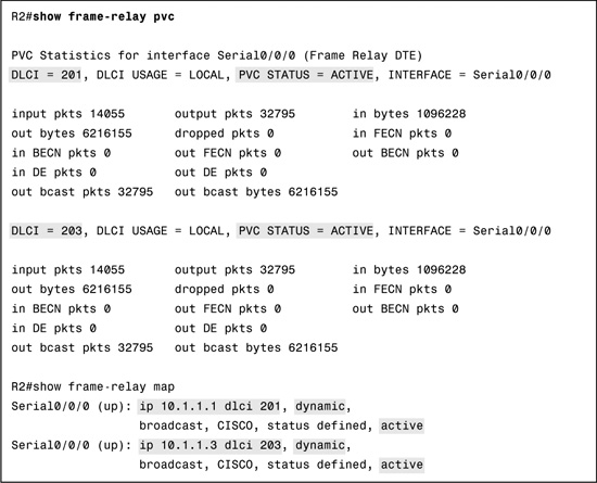
Although the DLCIs for each PVC are shown in Figure 2-9, they were not needed for our basic Frame Relay configuration. Inverse ARP automatically mapped the remote IP address with the necessary local DLCI to reach the remote network. This dynamic process can be verified with the show frame-relay pvc and show frame-relay map as shown in Example 2-4 for R2.
Although in a production network you would probably use Inverse ARP, for the exam, you need to know how to configure the static map command statements. Example 2-5 lists the static Frame Relay map for the three routers shown in Figure 2-9, along with the configuration used to disable Inverse ARP.
Example 2-5 Manually Configuring Frame Relay Mapping
R1(config)#interface s0/0/0
R1(config-if)#frame-relay map ip 10.1.1.2 102 broadcast
R1(config-if)#frame-relay map ip 10.1.1.3 103 broadcast
_______________________________________________________
R2(config)#interface serial 0/0/0
R2(config-if)#frame-relay map ip 10.1.1.1 201 broadcast
R2(config-if)#frame-relay map ip 10.1.1.3 203 broadcast
_______________________________________________________
R3(config)#interface serial 0/0/0
R3(config-if)#frame-relay map ip 10.1.1.1 301 broadcast
R3(config-if)#frame-relay map ip 10.1.1.2 302 broadcast
Note The broadcast keyword is required when the router needs to send broadcasts or multicasts to the neighboring router—for example, to support routing protocol messages such as Hellos.
Partial Mesh with One Subnet per PVC
The network in Figure 2-10 is a modification of Figure 2-9. R2 is now serving as the hub router for the spoke routers R1 and R2. This reduces the cost of the Frame Relay implementation from three PVCs to two PVCs. This configuration uses one subnet per PVC and point-to-point subinterfaces. Examples 2-6 through 2-8 show the configuration for this network.
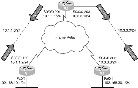
Example 2-6 Frame Relay Partial Mesh with One Subnet per PVC: R2
R2(config)#interface serial 0/0/0
R2(config-if)#encapsulation frame-relay
R2(config-if)#interface serial 0/0/0.201
R2(config-if)#interface serial 0/0/0.201 point-to-point
R2(config-subif)#ip address 10.1.1.1 255.255.255.0
R2(config-subif)#frame-relay interface-dlci 201
R2(config-subif)#interface serial 0/0/0.203 point-to-point
R2(config-subif)#ip address 10.3.3.1 255.255.255.0
R2(config-subif)#frame-relay interface-dlci 203
Two new commands create the configuration required with point-to-point subinterfaces. First, the interface serial 0/0/0.201 point-to-point command creates logical subinterface number 201 under physical interface Serial 0/0/0 on R2. The frame-relay interface-dlci 201 subinterface subcommand then tells the router which single DLCI is associated with that subinterface. In the example, subinterface numbers and DLCIs match, but this is not a requirement—only a convenient method to help identify which DLCI the subinterface belongs to.
To understand why we need the frame-relay interface-dlci command, consider R2. R2 receives LMI messages on Serial0/0/0 stating that two PVCs, with DLCIs 201 and 203, are up. Which PVC goes with which subinterface? Cisco IOS Software needs to associate the correct PVC with the correct subinterface. This is accomplished with the frame-relay interface-dlci command.
Frame Relay Verification
Examples of the show frame-relay pvc and show frame-relay map commands were shown previously in Example 2-4. The show frame-relay pvc command lists useful management information. For instance, the packet counters for each VC, plus the counters for FECN and BECN, can be particularly useful. Likewise, comparing the packets/bytes sent on one router versus the counters of what is received on the router on the other end of the VC is also quite useful. This reflects the number of packets/bytes lost inside the Frame Relay cloud. Also, the PVC status is a great place to start when troubleshooting.
The show frame-relay map command lists mapping information. In a fully meshed network, in which the configuration does not use any subinterfaces, a Layer 3 address is listed with each DLCI. For a point-to-point subinterface configuration, a DLCI is listed in each entry, but no mention of corresponding Layer 3 addresses is made. The reason is that the information is stored somewhere else. Subinterfaces require the use of the frame-relay interface-dlci configuration command.
The debug frame-relay lmi command shown in Example 2-9 can be used to verify that the physical interface is sending and receiving LMI messages from the local Frame Relay switch.
Example 2-9 Frame Relay debug Output
R2#debug frame-relay lmi
Serial0/0/0(out): StEnq, myseq 1, yourseen 0, DTE up
datagramstart = 0xE7829994, datagramsize = 13
FR encap = 0x00010308
00 75 51 01 00 53 02 01 00
Serial0/0/0(in): Status, myseq 1, pak size 21
RT IE 1, length 1, type 0
KA IE 3, length 2, yourseq 1 , myseq 1
PVC IE 0x7 , length 0x6 , dlci 201, status 0x0 , bw 0
Troubleshooting WAN Implementations
Troubleshooting your overall WAN implementation—not just Frame Relay aspects—often starts with investigating the state of the local router’s serial interface. The show interfaces serial command in Example 2-10 has the default HDLC encapsulation.
Example 2-10 Output from the show interfaces Command
R1#show interface serial 0/0/0
Serial0/0/0 is up, line protocol is up (connected)
Hardware is HD64570
Description: Link to R2
Internet address is 10.1.1.1/30
MTU 1500 bytes, BW 1544 Kbit, DLY 20000 usec, rely 255/255, load 1/255
Encapsulation HDLC, loopback not set, keepalive set (10 sec)
Last input never, output never, output hang never
Last clearing of "show interface" counters never
Input queue: 0/75/0 (size/max/drops); Total output drops: 0
Queueing strategy: weighted fair
Output queue: 0/1000/64/0 (size/max total/threshold/drops)
Conversations 0/0/256 (active/max active/max total)
Reserved Conversations 0/0 (allocated/max allocated)
5 minute input rate 3 bits/sec, 0 packets/sec
5 minute output rate 2 bits/sec, 0 packets/sec
3 packets input, 210 bytes, 0 no buffer
Received 0 broadcasts, 0 runts, 0 giants, 0 throttles
0 input errors, 0 CRC, 0 frame, 0 overrun, 0 ignored, 0 abort
2 packets output, 140 bytes, 0 underruns
0 output errors, 0 collisions, 0 interface resets
0 output buffer failures, 0 output buffers swapped out
0 carrier transitions
DCD=up DSR=up DTR=up RTS=up CTS=up
Highlighted in the output are the three main areas to look first for possible errors.
![]() The interface must be “up” and “up” before it can forward traffic.
The interface must be “up” and “up” before it can forward traffic.
![]() The IP address and subnet mask must be configured correctly.
The IP address and subnet mask must be configured correctly.
![]() The encapsulation must be correct: HDLC, PPP, or Frame Relay.
The encapsulation must be correct: HDLC, PPP, or Frame Relay.
Potential errors two and three and their solutions are relatively straightforward: correct the IP addressing or correct the encapsulation. The show interfaces serial command returns one of six possible states. You can see any of the following possible states in the interface status line:
![]() Serial x is up, line protocol is up
Serial x is up, line protocol is up
![]() Serial x is down, line protocol is down
Serial x is down, line protocol is down
![]() Serial x is up, line protocol is down
Serial x is up, line protocol is down
![]() Serial x is up, line protocol is up (looped)
Serial x is up, line protocol is up (looped)
![]() Serial x is up, line protocol is down (disabled)
Serial x is up, line protocol is down (disabled)
![]() Serial x is administratively down, line protocol is down
Serial x is administratively down, line protocol is down
Troubleshooting Layer 1 Problems
A down line status on the serial link typically points to a Layer 1 problem. The following list describes the most likely reasons:
![]() The leased line is down (a telco problem).
The leased line is down (a telco problem).
![]() The line from the telco is not plugged in to either or both CSU/DSUs.
The line from the telco is not plugged in to either or both CSU/DSUs.
![]() A CSU/DSU has failed or is misconfigured.
A CSU/DSU has failed or is misconfigured.
![]() A serial cable from a router to its CSU/DSU is disconnected or faulty.
A serial cable from a router to its CSU/DSU is disconnected or faulty.
The details of how to further isolate these four problems is beyond the scope of the CCNA exam.
One other common physical layer problem can occur that results in both routers’ interfaces being in an up/down state. On a back-to-back serial link, if the required clock rate command is missing on the router with a DCE cable installed, both routers’ serial interfaces will fail and end up with a line status of up but a line protocol status of down.
To check for this error, use the show controllers command on the side that should be DCE. You might be surprised to find that a DTE cable is attached. Or you might discover that no clock is set, as shown in Example 2-11.
Troubleshooting Layer 2 Problems
Table 2-1 lists three common data-link layer problems.
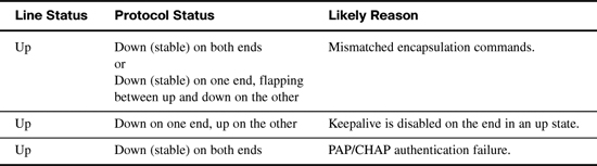
The first problem is easy to identify and fix. As we have seen, the show interfaces command will tell you the encapsulation type currently used on the interface.
The second problem in Table 2-1 relates to keepalives sent by Cisco routers by default every 10 seconds. This feature helps a router recognize when a link is no longer functioning so that the router can bring down the interface, hoping to then use an alternative IP route. If one end of the link is configured with the no keepalives command, it will remain in the “up” and “up” state. However, the other side of the link will continually flap up and down because it is not receiving keepalives. You can see whether keepalives are being sent with the show interfaces command, as highlighted in the partial output in Example 2-12.
Example 2-12 Verifying Keepalives with the show interfaces Command
R1#show interface serial 0/0/0
Serial0/0/0 is up, line protocol is up (connected)
Hardware is HD64570
Description: Link to R2
Internet address is 10.1.1.1/30
MTU 1500 bytes, BW 1544 Kbit, DLY 20000 usec, rely 255/255, load 1/255
Encapsulation HDLC, loopback not set, keepalive set (10 sec)
Last input never, output never, output hang never
The third problem in Table 2-1 is the result of an authentication failure between the two routers on each side of the link. Use the debug ppp authentication command to discover the root cause why authentication is failing.
In Example 2-13, we know that either the username or password is misconfigured on one or both sides of the link.
Example 2-13 PPP CHAP Authentication Failure in debug ppp authentication Output
R1#debug ppp authentication
PPP authentication debugging is on
Se0/0/0 PPP: Authorization required
Se0/0/0 CHAP: O CHALLENGE id 57 len 23 from "R1"
Se0/0/0 CHAP: I CHALLENGE id 66 len 23 from "R2"
Se0/0/0 CHAP: Using hostname from unknown source
Se0/0/0 CHAP: Using password from AAA
Se0/0/0 CHAP: O RESPONSE id 66 len 23 from "R1"
Se0/0/0 CHAP: I RESPONSE id 57 len 23 from "R2"
Se0/0/0 PPP: Sent CHAP LOGIN Request
Se0/0/0 PPP: Received LOGIN Response FAIL
Se0/0/0 CHAP: O FAILURE id 57 len 25 msg is "Authentication failed"
Troubleshooting Layer 3 Problems
A serial interface can be in the “up” and “up” state on both sides of the router, yet connectivity between the two routers fails because of a Layer 3 misconfiguration.
For default HDLC interfaces, if the IP addresses configured on the serial interfaces on the two routers are in different subnets, a ping to the IP address on the other end of the link will fail because the routers do not have a matching route.
Be careful with PPP in this same situation. With misconfigured IP addresses, both routers’ interfaces are in the “up” and “up” state, but the ping to the other router’s IP address actually works. PPP advertises its serial interface IP address to the other router, with a /32 prefix, which is a route to reach just that one host. So, both routers have a route with which to route packets to the other end of the link, even though two routers on opposite ends of a serial link have mismatched their IP addresses.
Although the ping to the other end of the link works, the routing protocols still do not advertise routes because of the IP subnet mismatch on the opposite ends of the link. So, when troubleshooting a network problem, do not assume that a serial interface in an “up” and “up” state is fully working, or even that a serial interface over which a ping works is fully working. Also make sure the routing protocol is exchanging routes and that the IP addresses are in the same subnet.