Day 31 Network Devices, Components, and Diagrams
CCNA 640-802 Exam Topics
![]() Describe the purpose and functions of various network devices.
Describe the purpose and functions of various network devices.
![]() Select the components required to meet a network specification.
Select the components required to meet a network specification.
![]() Describe the components required for network and Internet communications.
Describe the components required for network and Internet communications.
![]() Interpret network diagrams.
Interpret network diagrams.
![]() Differentiate between LAN/WAN operation and features.
Differentiate between LAN/WAN operation and features.
Key Points
At its most fundamental level, a network can be divided into four elements:
![]() The rules
The rules
![]() The messages
The messages
![]() The media
The media
![]() The devices
The devices
For today’s exam topics, we will focus on the devices used in today’s networks, the media used to interconnect those devices, and the different types of network topologies.
Devices
Hubs and switches are used to connect end devices to a single LAN. The following describes when to use a hub and when to use a switch:
![]() Hubs are typically chosen as an intermediary device within a very small LAN where bandwidth usage is not an issue or cost limitations exist. In today’s networks, hubs are being replaced by switches.
Hubs are typically chosen as an intermediary device within a very small LAN where bandwidth usage is not an issue or cost limitations exist. In today’s networks, hubs are being replaced by switches.
![]() Switches are preferred over hubs as a local-area network (LAN) intermediary device because a switch can segment collision domains and provide enhanced security.
Switches are preferred over hubs as a local-area network (LAN) intermediary device because a switch can segment collision domains and provide enhanced security.
Switches
When choosing a switch, the main factors to consider are the following:
![]() Cost: Determined by the number and type of ports, network management capabilities, embedded security technologies, and optional advanced switching technologies.
Cost: Determined by the number and type of ports, network management capabilities, embedded security technologies, and optional advanced switching technologies.
![]() Interface characteristics: Sufficient number of ports for now as well as future expansion; uplink speeds; mixture of UTP and fiber; modularity.
Interface characteristics: Sufficient number of ports for now as well as future expansion; uplink speeds; mixture of UTP and fiber; modularity.
![]() Hierarchical network layer: Switches at the access layer have different requirements than switches at the distribution or core layers.
Hierarchical network layer: Switches at the access layer have different requirements than switches at the distribution or core layers.
Access Layer Switches
Access layer switches facilitate the connection of end devices to the network. Features of access layer switches include the following:
![]() Port security
Port security
![]() VLANs
VLANs
![]() Fast Ethernet/Gigabit Ethernet
Fast Ethernet/Gigabit Ethernet
![]() Power over Ethernet (PoE)
Power over Ethernet (PoE)
![]() Link aggregation
Link aggregation
![]() Quality of service (QoS)
Quality of service (QoS)
Cisco access layer switches include the Catalyst Express 500, Catalyst 2960, Catalyst 3560, and Catalyst 3750 Catalyst product lines.
Distribution Layer Switches
Distribution layer switches receive the data from the access layer switches and forward the data to the core layer switches. Features of distribution layer switches include the following:
![]() Layer 3 support
Layer 3 support
![]() High forwarding rate
High forwarding rate
![]() Gigabit Ethernet/10 Gigabit Ethernet
Gigabit Ethernet/10 Gigabit Ethernet
![]() Redundant components
Redundant components
![]() Security policies/access control lists
Security policies/access control lists
![]() Link aggregation
Link aggregation
![]() Quality of service (QoS)
Quality of service (QoS)
Cisco distribution layer switches include the Catalyst 4500, Catalyst 4900, and Catalyst 6500 product lines.
Core Layer Switches
Core layer switches make up the backbone and are responsible for handling the majority of data on a switched LAN. Features of core layer switches include the following:
![]() Layer 3 support
Layer 3 support
![]() Very high forwarding rate
Very high forwarding rate
![]() Gigabit Ethernet/10 Gigabit Ethernet
Gigabit Ethernet/10 Gigabit Ethernet
![]() Link aggregation
Link aggregation
![]() Quality of service (QoS)
Quality of service (QoS)
The Catalyst 6500 product line is ideal for dedicated core switches in very large network environments.
Note You are not required to know the Cisco Catalyst product line for the CCNA exam. Exam questions are platform neutral. Examples given here are for your information only.
Routers
Routers are the primary devices used to interconnect networks—LANs, WANs, and WLANs. When you choose a router, the main factors to consider are the following:
![]() Expandability: Provides flexibility to add new modules as needs change.
Expandability: Provides flexibility to add new modules as needs change.
![]() Media: Determines the type of interfaces the router needs to support the various network connections.
Media: Determines the type of interfaces the router needs to support the various network connections.
![]() Operating system features: Determines the version of IOS loaded on the router. Different IOS versions support different feature sets. Features to consider include security, QoS, VoIP, routing complexity, and other services.
Operating system features: Determines the version of IOS loaded on the router. Different IOS versions support different feature sets. Features to consider include security, QoS, VoIP, routing complexity, and other services.
Media
Messages are encoded and then placed on the media. Encoding is the process of converting data into patterns of electrical, light, or electromagnetic energy so that it can be carried on the media.
Table 31-1 summarizes the three most common networking media in use today.

Each media type has its advantages and disadvantages. When you choose the media, consider each of the following:
![]() Cable length: Does the cable need to span across a room or from building to building?
Cable length: Does the cable need to span across a room or from building to building?
![]() Cost: Does the budget allow for using a more expensive media type?
Cost: Does the budget allow for using a more expensive media type?
![]() Bandwidth: Does the technology used with the media provide adequate bandwidth?
Bandwidth: Does the technology used with the media provide adequate bandwidth?
![]() Ease of installation: Does the implementation team have the ability to install the cable, or is a vendor required?
Ease of installation: Does the implementation team have the ability to install the cable, or is a vendor required?
![]() Susceptible to EMI/RFI: Is the local environment going to interfere with the signal?
Susceptible to EMI/RFI: Is the local environment going to interfere with the signal?
Table 31-2 summarizes media standards for LAN cabling.

End devices are those pieces of equipment that are either the original source or the final destination of a message. Intermediary devices connect end devices to the network to assist in getting a message from the source end device to the destination end device.
Connecting devices in a LAN is usually done with unshielded twisted-pair (UTP) cabling. Although many newer devices have an automatic crossover feature that allows you to connect either a straight-through or crossover cable, most devices currently require you to use one or the other.
Use straight-through cables for the following connections:
![]() Switch to router Ethernet port
Switch to router Ethernet port
![]() Computer to switch
Computer to switch
![]() Computer to hub
Computer to hub
Use crossover cable for the following connections:
![]() Switch to switch
Switch to switch
![]() Switch to hub
Switch to hub
![]() Hub to hub
Hub to hub
![]() Router to router (Ethernet ports)
Router to router (Ethernet ports)
![]() Computer to computer
Computer to computer
![]() Computer to router Ethernet port
Computer to router Ethernet port
LANs and WANs
A local-area network (LAN) is a network of computers and other components located relatively close together in a limited area. LANs can vary widely in size from one computer in a home office to hundreds of computers in a corporate office; however, in general, a LAN spans a limited geographical area. The fundamental components of a LAN include the following:
![]() Computers
Computers
![]() Interconnections (NICs and the media)
Interconnections (NICs and the media)
![]() Networking devices (hubs, switches, and routers)
Networking devices (hubs, switches, and routers)
![]() Protocols (Ethernet, IP, ARP, DHCP, DNS, and so on)
Protocols (Ethernet, IP, ARP, DHCP, DNS, and so on)
A wide-area network (WAN) generally connects LANs that are geographically separated. A collection of LANs connected by one or more WANs is called an internetwork—thus we have the Internet. The term intranet is often used to refer to a privately owned connection of LANs and WANs.
Depending on the type of service, connecting to the WAN is normally done in one of four ways:
![]() RJ-11 connection to a dialup or DSL modem
RJ-11 connection to a dialup or DSL modem
![]() Cable coaxial connection to a cable modem
Cable coaxial connection to a cable modem
![]() 60-pin serial connection to a CSU/DSU
60-pin serial connection to a CSU/DSU
![]() RJ-45 T1 Controller connection to a CSU/DSU
RJ-45 T1 Controller connection to a CSU/DSU
With the growing number of teleworkers, enterprises have an increasing need for secure, reliable, and cost-effective ways to connect people working in small offices or home offices (SOHOs) or other remote locations to resources on corporate sites. Remote connection technologies to support teleworkers include the following:
![]() Traditional private WAN technologies, including Frame Relay, ATM, and leased lines
Traditional private WAN technologies, including Frame Relay, ATM, and leased lines
![]() IPsec virtual private networks (VPNs)
IPsec virtual private networks (VPNs)
![]() Remote secure VPN access through a broadband connection over the public Internet
Remote secure VPN access through a broadband connection over the public Internet
Components needed for teleworker connectivity include the following:
![]() Home office components: Computer, broadband access (cable or DSL), and a VPN router or VPN client software installed on the computer.
Home office components: Computer, broadband access (cable or DSL), and a VPN router or VPN client software installed on the computer.
![]() Corporate components: VPN-capable routers, VPN concentrators, multifunction security appliances, authentication, and central management devices for resilient aggregation and termination of the VPN connections.
Corporate components: VPN-capable routers, VPN concentrators, multifunction security appliances, authentication, and central management devices for resilient aggregation and termination of the VPN connections.
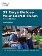
Networking Icons
Before you can interpret networking diagrams or topologies, you first must understand the symbols or icons used to represent different networking devices and media. The icons shown in Figure 31-1 are the most common networking symbols for CCNA studies.

Physical and Logical Topologies
Network diagrams are more often referred to as topologies. A topology graphically displays the interconnection methods used between devices.
Physical topologies refer to the physical layout of devices and how they are cabled. There are seven basic physical topologies, as shown in Figure 31-2.
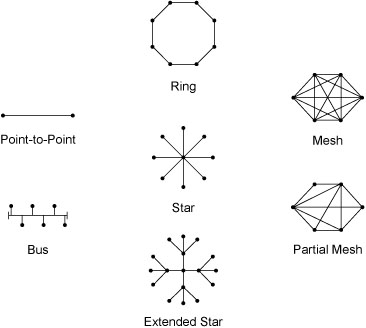
Logical topologies refer to the way a signal travels from one point on the network to another and are largely determined by the access method—deterministic or nondeterministic. Ethernet is a nondeterministic access method. Logically, Ethernet operates as a bus topology. However, Ethernet networks are almost always physically designed as a star or extended star.
Other access methods use a deterministic access method. Token Ring and Fiber Distributed Data Interface (FDDI) both logically operate as ring, passing data from one station to the next. Although these networks can be designed as a physical ring, like Ethernet, they are often designed as a star or extended star. But logically, they operate like a ring.
The Hierarchical Network Model
Hierarchical network design involves dividing the network into discrete layers. Each layer provides specific functions that define its role within the overall network. By separating the various functions that exist on a network, the network design becomes modular, which facilitates scalability and performance. The hierarchical design model is broken up into three layers as follows:
![]() Access layer: Provides local and remote user access
Access layer: Provides local and remote user access
![]() Distribution layer: Controls the flow of data between the access and core layers
Distribution layer: Controls the flow of data between the access and core layers
![]() Core layer: High-speed redundant backbone
Core layer: High-speed redundant backbone
Figure 31-3 shows an example of the hierarchical model.

The Enterprise Architecture
The Cisco Enterprise Architecture is designed to provide network planners with a roadmap for network growth as the business moves through different stages. By following the suggested roadmap, IT managers can plan for future network upgrades that will integrate seamlessly into the existing network and support the ever-growing need for services. The Cisco Enterprise Architecture consists of the following modules:
![]() Enterprise Campus Architecture: Refers to a group of buildings that contain many LANs.
Enterprise Campus Architecture: Refers to a group of buildings that contain many LANs.
![]() Enterprise Edge Architecture: Offers connectivity to voice, video, and data to and from service providers.
Enterprise Edge Architecture: Offers connectivity to voice, video, and data to and from service providers.
![]() Enterprise Branch Architecture: Extends the applications and services within the campus to multiple remote locations.
Enterprise Branch Architecture: Extends the applications and services within the campus to multiple remote locations.
![]() Enterprise Data Center Architecture: Manages and maintains the enterprise’s data systems (such as its server farms).
Enterprise Data Center Architecture: Manages and maintains the enterprise’s data systems (such as its server farms).
![]() Enterprise Teleworker Architecture: Connects employee home offices and “road warriors” to the network resources of the enterprise.
Enterprise Teleworker Architecture: Connects employee home offices and “road warriors” to the network resources of the enterprise.
Figure 31-4 shows a graphical representation of the Cisco Enterprise Architecture and how each module interconnects.

Figure 31-5 shows a network diagram depicting most of the modules of the Enterprise Architecture in a sample implementation of the Enterprise Architecture—the Enterprise Data Center is excluded. Notice how the three layers of the hierarchical model (access, distribution, and core) are integrated into the Enterprise Architecture.

Network Documentation
Documentation for your network should include, at a minimum, the following major categories:
![]() Router and switch documentation: Includes device type, IOS image, hostname, location, addresses, and other important information.
Router and switch documentation: Includes device type, IOS image, hostname, location, addresses, and other important information.
![]() End-system documentation: Includes device names, OS, addressing details, network impact (such as bandwidth usage).
End-system documentation: Includes device names, OS, addressing details, network impact (such as bandwidth usage).
![]() Network topology diagram: Includes all devices and shows the connections as well as the interface designations and addressing scheme.
Network topology diagram: Includes all devices and shows the connections as well as the interface designations and addressing scheme.
More often than not, a network’s documentation is less than complete. To complete the documentation, you might have to gather information directly from the devices. Commands that are useful to this process include the following:
![]() ping: Tests direct connectivity between two devices
ping: Tests direct connectivity between two devices
![]() telnet: Tests remote access as well as Layer 7 functionality
telnet: Tests remote access as well as Layer 7 functionality
![]() show ip interface brief: Verifies interface statuses
show ip interface brief: Verifies interface statuses
![]() show ip route: Verifies routing operations
show ip route: Verifies routing operations
![]() show cdp neighbor detail: Gathers useful information about directly connected Cisco devices
show cdp neighbor detail: Gathers useful information about directly connected Cisco devices