
Day 20 Host Addressing, DHCP, and DNS
CCNA 640-802 Exam Topics
![]() Implement static and dynamic addressing services for hosts in a LAN environment.
Implement static and dynamic addressing services for hosts in a LAN environment.
![]() Identify and correct common problems associated with IP addressing and host configurations.
Identify and correct common problems associated with IP addressing and host configurations.
![]() Explain the operation and benefits of using DHCP and DNS.
Explain the operation and benefits of using DHCP and DNS.
![]() Configure, verify and troubleshoot DHCP and DNS operation on a router (CLI/SDM).
Configure, verify and troubleshoot DHCP and DNS operation on a router (CLI/SDM).
Key Topics
Today we review static and dynamic IP addressing for end devices as well as the protocols surrounding host-to-host communications including Address Resolution Protocol (ARP), Domain Name System (DNS), and Dynamic Host Configuration Protocol (DHCP). Because a Cisco router can also be a DHCP server, we will review those commands. Also, because an IP addressing implementation is not always perfect, we review the testing tools at your disposal to track down and solve connectivity problems related to host addressing.
Addressing Devices
Addresses in the network can be assigned to hosts statically or dynamically. Static addresses have some advantages over dynamic addresses. For example, if hosts normally access a server, a printer, or other devices at a particular IP address, it might cause problems if that address changed. Additionally, static assignment of addressing information can provide increased control of network resources. However, it can be time consuming to enter the information on each host, and because a duplicated address affects the host operation, care must be taken not to reuse an address.
To configure a static address on a PC running Windows XP, access the Internet Protocol (TCP/IP) Properties dialog box as shown in Figure 20-1 and enter all the necessary IP configuration information.

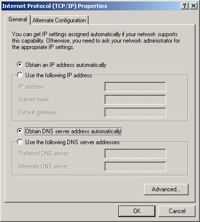
Because of the challenges associated with static address management, end-user devices often have addresses dynamically assigned, using DHCP.
To configure a Windows PC to use DHCP, access the Internet Protocol (TCP/IP) Properties dialog box as shown in Figure 20-2 and click both radio buttons for obtaining addressing information automatically.
ARP
For IP communication on Ethernet-connected networks to take place, the logical (IP) address needs to be bound to the physical (MAC) address of its destination. This process is carried out using ARP. Figure 20-3 shows an example of mapping a Layer 2 address to a Layer 3 address.

To send data to a destination, a host on an Ethernet network must know the physical (MAC) address of the destination. ARP provides the essential service of mapping IP addresses to physical addresses on a network.
The resulting mappings or address bindings are kept in a table and depending upon the operating system can be anywhere from 2 to 20 minutes, or even longer before the entry expires. Every networking device that sends IP packets on an Ethernet network segment maintains an ARP table in memory similar to the table shown in Example 20-1.

Example 20-2 shows what an ARP table looks like on a Cisco device.

Regardless of the format of the output, the ARP table shows the IP to MAC address bindings.
ARP helps end devices communicate on the same LAN. But what happens when an end device wants to communicate with another device on a remote LAN?
If the destination host is not on the local network, the source sends the frame to the local router. To do this, the source will use the default gateway’s MAC address in the frame. The default gateway (the local router), will then take care of routing the packet to the next hop.
DNS
IP packets require destination and source IP addresses. But most humans would have a hard time remembering all the IP addresses for their favorite destinations. Hence, the Domain Name System (DNS) was created to convert recognizable names into IP addresses so that end devices can then encapsulate a packet with the necessary addressing information.
The DNS server acts as the phone book for the Internet: It translates human-readable computer hostnames—for example, http://www.cisco.com—into the IP addresses that networking equipment needs for delivering information. To see this “phone book” in action on a Windows machine, enter the command nslookup as shown in Example 20-3. Then enter the name for a website.
Notice that the DNS server, which is located at IP address 64.102.6.247, returned the IP address 198.133.219.25 for www.cisco.com.
DNS uses a hierarchical system to create a name database to provide name resolution. At the top of the hierarchy, the root servers maintain records about how to reach the top-level domain servers, which in turn have records that point to the secondary-level domain servers, and so on.
The different top-level domains represent either the type of organization or the country of origin. The following are examples of top-level domains:
![]() .co: Colombia
.co: Colombia
![]() .com: A business or industry
.com: A business or industry
![]() .jp: Japan
.jp: Japan
![]() .org: A nonprofit organization
.org: A nonprofit organization
DHCP
DHCP allows a host to obtain an IP address dynamically when it connects to the network. The DHCP server is contacted by sending a request, and an IP address is requested. The DHCP server chooses an address from a configured range of addresses called a pool and assigns it to the host client for a set period. Figure 20-4 graphically shows the process for how a DHCP server allocates IP addressing information to a DHCP client.

When a DHCP-configured device boots up or connects to the network, the client broadcasts a DHCPDISCOVER packet to identify any available DHCP servers on the network. A DHCP server replies with a DHCPOFFER, which is a lease offer message with an assigned IP address, subnet mask, DNS server, and default gateway information, as well as the duration of the lease.
The client can receive multiple DHCPOFFER packets if the local network has more than one DHCP server. The client must choose between them and broadcast a DHCPREQUEST packet that identifies the explicit server and lease offer that it is accepting.
Assuming that the IP address is still valid, the chosen server returns a DHCPACK (acknowledgment) message finalizing the lease. If the offer is no longer valid for some reason, the chosen server responds to the client with a DHCPNAK (negative acknowledgment) message. After it is leased, the client will renew prior to the lease expiration through another DHCPREQUEST. If the client is powered down or taken off the network, the address is returned to the pool for reuse.
Configuring on a Cisco Router as a DHCP Server
Note Because of space limitations, only the CLI method for configuring DHCP is reviewed here. However, because the exam topic includes both the CLI and Security Device Manager (SDM) methods, review the SDM method by consulting your study resources.
The steps to configure a router as a DHCP server are as follows:
Step 1 Use the ip dhcp excluded-address low-address [high-address] command to identify an address or range of addresses to exclude from the DHCP pool. For example:
R1(config)# ip dhcp excluded-address 192.168.10.1 192.168.10.9
R1(config)# ip dhcp excluded-address 192.168.10.254
Step 2 Create the DHCP pool using the ip dhcp pool pool-name command, which will then place you in DHCP config mode, as demonstrated here:
R1(config)# ip dhcp pool LAN-POOL-10
R1(dhcp-config)#
Step 3 Finally, configure the IP addressing parameter you need to automatically assign to requesting clients. Table 20-1 lists the required commands.
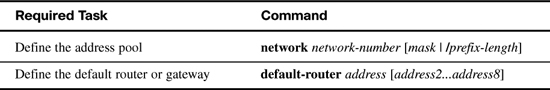
Table 20-2 lists some of the more common optional DHCP tasks.

Figure 20-5 shows a sample DHCP topology.

Example 20-4 shows DHCP required and optional commands to configure R1 as the DHCP server for both LANs.
Example 20-4 DHCP Configuration Example
R1(config)#ip dhcp excluded-address 192.168.10.1 192.168.10.9
R1(config)#ip dhcp excluded-address 192.168.10.254
R1(config)#ip dhcp excluded-address 192.168.11.1 192.168.11.9
R1(config)#ip dhcp excluded-address 192.168.11.254
R1(config)#ip dhcp pool LAN-POOL-10
R1(dhcp-config)#network 192.168.10.0 255.255.255.0
R1(dhcp-config)#default-router 192.168.10.1
R1(dhcp-config)#dns-server 192.168.50.195 209.165.202.158
R1(dhcp-config)#domain-name cisco.com
R1(dhcp-config)#lease 2
R1(dhcp-config)#netbios-name-server 192.168.10.254
R1(dhcp-config)#ip dhcp pool LAN-POOL-11
R1(dhcp-config)#network 192.168.11.0 255.255.255.0
R1(dhcp-config)#default-router 192.168.11.1
R1(dhcp-config)#dns-server 192.168.50.195 209.165.202.158
R1(dhcp-config)#domain-name cisco.com
R1(dhcp-config)#lease 2
R1(dhcp-config)#netbios-name-server 192.168.11.254
R1(dhcp-config)#end
Cisco IOS Software supports DHCP service by default. To disable it, use the global command no service dhcp.
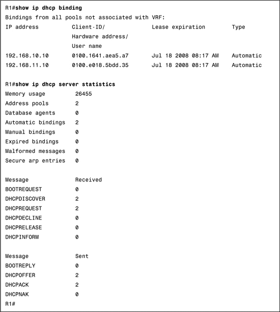
To verify DHCP operations on the router, use the commands shown in Example 20-5.
Because PC1 and PC2 are connected to the LANs, each automatically receives its IP addressing information from the router’s DHCP server. Example 20-6 shows the output from the ipconfig/all command on PC1.
Example 20-6 DHCP Client Configuration
C:>ipconfig/all
Windows IP Configuration
Host Name . . . . . . . . . . . . . . : ciscolab
Primary Dns Suffix . . . . . . . . . . :
Node Type . . . . . . . . . . . . . . . . : Hybrid
IP Routing Enabled. . . . . . . . . . . : No
WINS Proxy Enabled. . . . . . . . . : No
Ethernet adapter Local Area Connection:
Connection-specific DNS Suffix . : cisco.com
Description . . . . . . . . . . . . . . . . . . . . : Intel(R) PRO/1000 PL
Physical Address. . . . . . . . . . . . . . . . . : 00-16-41-AE-A5-A7
Dhcp Enabled. . . . . . . . . . . . . . . . . . . : Yes
Autoconfiguration Enabled . . . . . . . . . : Yes
IP Address. . . . . . . . . . . . . . . . . . . . . : 192.168.10.11
Subnet Mask . . . . . . . . . . . . . . . . . . . : 255.255.255.0
Default Gateway . . . . . . . . . . . . . . . . : 192.168.10.1
DHCP Server . . . . . . . . . . . . . . . . . . : 192.168.10.1
DNS Servers . . . . . . . . . . . . . . . . . . . : 192.168.50.195
209.165.202.158
Primary WINS Server . . . . . . . . . . . . : 192.168.10.254
Lease Obtained. . . . . . . . . . . . . . . . . . : Wednesday, July 16, 2008 8:16:59 AM
Lease Expires . . . . . . . . . . . . . . . . . . . : Friday, July 18, 2008 8:16:59 AM
C:>
To release the DHCP configuration on a Windows-based client, enter the command ipconfig/release. To renew the DHCP configuration, enter the command ipconfig/renew.
In a complex network, the DHCP servers are usually contained in a server farm. Therefore, clients typically are not on the same subnet as the DHCP server, as shown in the previous example. To ensure broadcasted DHCPDISCOVER messages are sent to the remote DHCP server, use the ip helper-address address command.
For example, in Figure 20-6 the DHCP server is located on the 192.168.11.0/24 LAN and is serving IP addressing information for both LANs.

Without the ip helper-address command, R1 would discard any broadcasts from PC1 requesting DHCP services. To configure R1 to relay DHCPDISCOVER messages, enter the following command:
R1(config)#interface fastethernet 0/0
R1(config-if)#ip helper-address 192.168.11.5
Notice the command is entered on the interface that will receive DHCP broadcasts. R1 then forwards DHCP broadcast messages as a unicast to 192.168.11.5. The ip helper-address command by default forwards the following eight UDP services:
![]() Port 37: Time
Port 37: Time
![]() Port 49: TACACS
Port 49: TACACS
![]() Port 53: DNS
Port 53: DNS
![]() Port 67: DHCP/BOOTP client
Port 67: DHCP/BOOTP client
![]() Port 69: TFTP
Port 69: TFTP
![]() Port 137: NetBIOS name service
Port 137: NetBIOS name service
![]() Port 138: NetBIOS datagram service
Port 138: NetBIOS datagram service
To specify additional ports, use the global command ip forward-protocol udp [port-number | protocol]. To disable broadcasts of a particular protocol, use the no form of the command.
Network Layer Testing Tools
The ping and tracert (traceroute for Cisco IOS) are commonly used to test connectivity and identify problems with host addressing.
Ping
For testing end-to-end connectivity between hosts, use the ping command. If the ping is successful, as shown in Examples 20-7 and 20-8, you know that at least one path exists to route traffic between the source and destination.
Example 20-7 Ping Output on a Windows PC
C:>ping 192.168.10.1
Pinging 192.168.10.1 with 32 bytes of data:
Reply from 192.168.10.1: bytes=32 time<1ms TTL=64
Reply from 192.168.10.1: bytes=32 time<1ms TTL=64
Reply from 192.168.10.1: bytes=32 time<1ms TTL=64
Reply from 192.168.10.1: bytes=32 time<1ms TTL=64
Ping statistics for 192.168.10.1:
Packets: Sent = 4, Received = 4, Lost = 0 (0% loss),
Approximate round trip times in milli-seconds:
Minimum = 0ms, Maximum = 0ms, Average = 0ms
C:>
Notice that the first ping failed (.). Most likely, this was due to a timeout while R1 initiated an ARP request to 192.168.10.10. After R1 had the MAC address for 192.168.10.10, it could then send the ICMP requests. The next four pings succeed (!). If the ping test fails for end-to-end connectivity, you might want to back up to the local machine to test your TCP/IP stack by pinging the 127.0.0.1 address. If this ping succeeds, test your connectivity to the default gateway. If this ping fails, check your physical connectivity and IP configuration.
If the ping succeeds to the default gateway, use traceroute to find where there is failure. Traceroute (tracert) allows you to observe the path between these hosts. The trace generates a list of hops that were successfully reached along the path, as shown in Example 20-9. This list can provide you with important verification and troubleshooting information.
Example 20-9 Sample tracert Output
C:> tracert www.cisco.com
Tracing route to www.cisco.com [198.133.219.25]
over a maximum of 30 hops:
1 87 ms 87 ms 89 ms sjck-access-gw2-vla30.cisco.com [10.20.0.94]
2 89 ms 88 ms 87 ms sjce-sbb1-gw1-gig3-7.cisco.com [171.69.14.245]
3 88 ms 87 ms 88 ms sjck-rbb-gw2-ten7-1.cisco.com [171.69.14.45]
4 90 ms 87 ms 95 ms sjck-corp-gw1-gig1-0-0.cisco.com [171.69.7.174]
5 90 ms 88 ms 92 ms sjce-dmzbb-gw1.cisco.com [128.107.236.38]
6 * * * Request timed out.
7 * * ^C
C:>
The tracert to www.cisco.com shows responses from the routers along the path. The local host sends a packet to the designation address of 198.133.219.2. The first response is a response from the host’s default gateway, 10.20.0.94.
When the final destination is reached, the host responds with either an ICMP Port Unreachable message or an ICMP Echo Reply message. In the case of Example 20-8, the asterisk (*) indicates the ICMP Time Exceeded message that there were no responses from the destination.