Day 14 Static, Default, and RIP Routing
CCNA 640-802 Exam Topics
![]() Perform and verify routing configuration tasks for a static or default route given specific routing requirements.
Perform and verify routing configuration tasks for a static or default route given specific routing requirements.
![]() Configure, verify, and troubleshoot RIPv2.
Configure, verify, and troubleshoot RIPv2.
Key Topics
Today we focus on static, default, and RIP routing for IPv4. Static routes are a common part of an enterprise’s routing policy. Static routes can be used to force traffic to use a specific path or to establish a default route out of the enterprise. Static routes are hard-coded into the routing table by the network administrator. Thus, a network administrator must monitor and maintain static routes to ensure connectivity.
Dynamic routing, on the other hand, automatically maintains routing information without a network administrator’s intervention. The first routing protocol, Routing Information Protocol (RIP), comes in two versions for IPv4 and another version for IPv6.
Static Route Configuration
One of the common uses for a static route is routing to a stub network. A stub network is a network accessed by a single route. To configure a static route, use the ip route command with the following relevant syntax:
Router(config)#ip route network-address subnet-mask {ip-address |
exit-interface}
Explanation for each parameter is as follows:
![]() network-address: Destination network address of the remote network to be added to the routing table.
network-address: Destination network address of the remote network to be added to the routing table.
![]() subnet-mask: Subnet mask of the remote network to be added to the routing table. The subnet mask can be modified to summarize a group of networks.
subnet-mask: Subnet mask of the remote network to be added to the routing table. The subnet mask can be modified to summarize a group of networks.
One or both of the following parameters are used:
![]() ip-address: Commonly referred to as the next-hop router’s IP address.
ip-address: Commonly referred to as the next-hop router’s IP address.
![]() exit-interface: Outgoing interface that would be used in forwarding packets to the destination network.
exit-interface: Outgoing interface that would be used in forwarding packets to the destination network.
Figure 14-1 and Table 14-1 show the topology and addressing scheme we are using today to review static and default routing.


Assume R1 is configured and knows about its own directly connected networks. Example 14-1 shows the routing table for R1 before any static routing is configured.

The remote networks that R1 does not know about are as follows:
![]() 172.16.1.0/24: The LAN on R2
172.16.1.0/24: The LAN on R2
![]() 192.168.1.0/24: The serial network between R2 and R3
192.168.1.0/24: The serial network between R2 and R3
![]() 192.168.2.0/24: The LAN on R3
192.168.2.0/24: The LAN on R3
Static Routes Using the “Next Hop” Parameter
Using the “next hop” parameter, R1 can be configured with three static routes—one for each of the networks R1 does not yet know about. Example 14-2 shows the command syntax.
The interface that routes to the next hop must be “up” and “up” before the static routes can be entered in the routing table. Example 14-3 verifies that the static routes are now in the routing table.

Notice that a route exists to the 172.16.2.0/24 network, which the “next hop” 172.16.2.2 belongs to. After performing a recursive lookup to find the exit interface, R1 will send packets for each of the three static routes out the Serial 0/0/0 interface.
Static Routes Using the Exit Interface Parameter
To avoid a recursive lookup and have a router immediately send packets to the exit interface, configure the static route using the exit-interface parameter instead of the “next hop” (ip-address) parameter.
For example, on R2 we can configure a static route to the 172.16.3.0/24 network and specify the Serial 0/0/0 interface as the exit interface:
R2(config)#ip route 172.16.3.0 255.255.255.0 serial 0/0/0
Any previous static routes to this network using a next-hop IP address should be removed. R2 now has a static route in its routing table, as shown in Example 14-4, that it can use immediately to route to the 172.16.3.0/24 network without having to do a recursive route lookup.

Default Static Routes
A default route is a special kind of static route used to represent all routes with zero or no bits matching. In other words, when there are no routes that have a more specific match in the routing table, the default route will be a match.
The destination IP address of a packet can match multiple routes in the routing table. For example, consider having the following two static routes in the routing table:
172.16.0.0/24 is subnetted, 3 subnets
S 172.16.1.0 is directly connected, Serial0/0/0
S 172.16.0.0/16 is directly connected, Serial0/0/1
A packet destined for 172.16.1.10, the packet’s destination IP address, matches both routes. However, the 172.16.1.0 route is the more specific route because the destination matches the first 24 bits, whereas the destination matches only the first 16 bits of the 172.16.0.0 route. Therefore, the router will use the route with the most specific match.
A default static route is a route that will match all packets. Commonly called a quad-zero route, a default static route uses 0.0.0.0 (thus, the term “quad-zero”) for both the network-address and subnet-mask parameter, as shown in this syntax:
Router(config)#ip route 0.0.0.0 0.0.0.0 {ip-address | exit-interface}
Referring to the topology shown in Figure 14-1, assume that R3 has a connection to the Internet. From the perspective of R2, all default traffic can be sent to R3 for routing outside the domain known to R2.
The following command configures R2 with a default static route pointing to R3 using the “next hop” parameter:
R2(config)#ip route 0.0.0.0 0.0.0.0 192.168.1.1
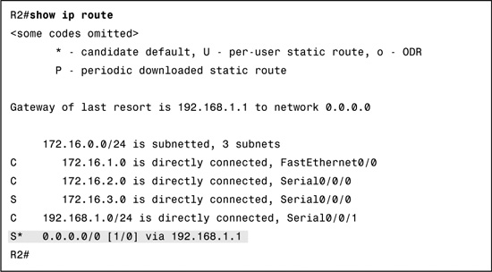
R2 now has a “gateway of last resort” listed in the routing table—a candidate default route indicated by the asterisk (*) next to the S code, as shown in Example 14-5.
From R1’s perspective, R2 is the default route. The following command configures R1 with a default static route pointing to R2 using the exit-interface parameter:
R1(config)#ip route 0.0.0.0 0.0.0.0 serial 0/0/0
Again, we can verify that the default route is now in the routing table for R1, as shown in Example 14-6.

After additional static routes are configured, the routing tables for R1 and R2 are complete. However, R3 does not have routes back to any of the 172.16.0.0 networks. So any traffic from PC1 to the PC3 will reach PC3, but return traffic from PC3 will be dropped by R3 because R3 does not have a route back to any of R1’s directly connected networks. We can see that the problem is with R3 from the traceroute output in Example 14-7.
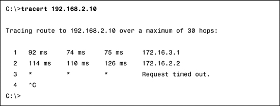
From the output, you can see that R2 (172.16.2.2) responded to PC1. R2 then routes the next trace to R3. We know this because R2 has a default route pointing to R3. However, when the trace arrives at R3, it does not have a route back to PC1, so it drops the packet. R3 needs a route back to the 172.16.3.0/24 network.
Before configuring three separate static routes for each of the 172.16.0.0 networks, notice that the three routes can be summarized into one route. We reviewed summary routes on Day 21, so we will not detail the process here. Example 14-8 shows the three routes in binary with the bits in common highlighted.
Therefore, the summary route would be 172.16.0.0/22. Although not part of the current addressing scheme, this summary static route would also include the route 172.16.0.0/24.
You can now configure R3 with one static route:
R3(config)#ip route 172.16.0.0 255.255.252.0 serial 0/0/1
Now PC1 can successfully trace a route to PC3 as shown in Example 14-9.

The trace is successful because R3 now has a route back to PC1’s network, as shown in Example 14-10.

RIP Concepts
Because RIPv2 is actually an enhancement of RIPv1, you should be able to compare and contrast the two version’s concepts and configurations. First, let’s look briefly at RIPv1.
RIPv1 Message Format
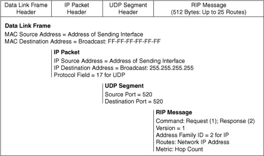
RIPv1 is a classful, distance vector routing protocol for IPv4. It uses hop count as its only metric for path selection with a hop count greater than 15 considered unreachable. RIPv1 routing messages are encapsulated in a UDP segment using port number 520 and are broadcast every 30 seconds. Figure 14-2 shows the RIPv1 message encapsulation from the data link layer up to and including the RIPv1 message.
RIPv1 Operation
Notice in the RIP message that RIP uses two message types specified in the Command field. Command 1 is a Request message and Command 2 is a Response message.
Each RIP-configured interface sends out a Request message on startup, requesting that all RIP neighbors send their complete routing tables. A Response message is sent back by RIP-enabled neighbors. When the requesting router receives the responses, it evaluates each route entry. If a route entry is new, the receiving router installs the route in the routing table. If the route is already in the table, the existing entry is replaced if the new entry has a better hop count. The startup router then sends a triggered update out all RIP-enabled interfaces containing its own routing table so that RIP neighbors can be informed of any new routes.
RIPv1 does not send subnet mask information in the update. Therefore, a router either uses the subnet mask configured on a local interface or applies the default subnet mask based on the address class. Because of this limitation, RIPv1 networks cannot be discontiguous, nor can they implement VLSM or supernetting.
RIP has a default administrative distance of 120. When compared to other interior gateway protocols, RIP is the least-preferred routing protocol.
RIPv1 Configuration
Figure 14-3 and Table 14-2 show the RIPv1 topology for our first scenario and the addressing scheme we will use to review RIPv1 configuration and verification.


In Figure 14-3, we are using six separate classful networks, so each network must be configured individually. Assuming the interfaces on R1, R2, and R3 are configured and active, Example 14-11 shows the RIPv1 configuration for the routers.
Example 14-11 RIPv1 Standard Configuration: Scenario A
R1(config)#router rip
R1(config-router)#network 192.168.1.0
R1(config-router)#network 192.168.2.0
_____________________________________
R2(config)#router rip
R2(config-router)#network 192.168.2.0
R2(config-router)#network 192.168.3.0
R2(config-router)#network 192.168.4.0
_____________________________________
R3(config)#router rip
R3(config-router)#network 192.168.4.0
R3(config-router)#network 192.168.5.0
RIPv1 Verification and Troubleshooting
The following verification commands, used in order, will quickly verify if routing is operational as intended.
![]() show ip route
show ip route
![]() show ip protocols
show ip protocols
![]() debug ip rip
debug ip rip
If routing is not functioning correctly, these commands will help you track down the problem in the most efficient manner.
To verify that routing is operational, start with the show ip route command. For the topology in Figure 14-3, all routes should be in the routing table for each router. Example 14-12 shows the routing table for R2.
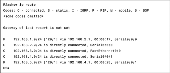
To better understand the output from the show ip route command, let’s focus on one RIP route learned by R2 and interpret the output shown in the routing table:
R 192.168.5.0/24 [120/1] via 192.168.4.1, 00:00:23, Serial0/0/1
Table 14-3 lists and describes each part of the output.

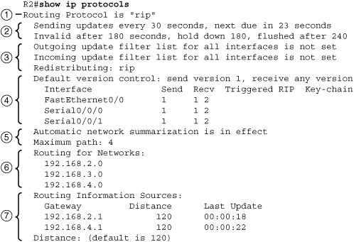
If the routing table is missing one or more expected routes, use the show ip protocols command on the local router first to make sure RIP is configured and operating correctly. This command displays the routing protocol that is currently configured on the router. The output can be used to verify most RIP parameters to confirm the following:
![]() RIP routing is configured.
RIP routing is configured.
![]() The correct interfaces send and receive RIP updates.
The correct interfaces send and receive RIP updates.
![]() The router advertises the correct networks.
The router advertises the correct networks.
![]() RIP neighbors are sending updates.
RIP neighbors are sending updates.
Figure 14-4 shows the output from the show ip protocols command, with numbers by each portion of the output. The descriptions that follow the figure correspond to the numbers in the figure.
-
The first line of output verifies that RIP routing is configured and running on R2.
-
These are the timers that show when the next round of updates will be sent out from this router—23 seconds from now, in the example.
-
Filtering and redistribution information shown here are both CCNP-level topics.
-
This block of output contains information about which RIP version is currently configured and which interfaces are participating in RIP updates.
-
This part of the output shows that R2 is currently summarizing at the classful network boundary and, by default, will use up to four equal-cost routes to load-balance traffic.
-
The classful networks configured with the network command are listed next. These are the networks that R2 will include in its RIP updates.
-
Here the RIP neighbors are listed as Routing Information Sources. Gateway is the next-hop IP address of the neighbor that is sending R2 updates. Distance is the AD that R2 uses for updates sent by this neighbor. Last Update is the seconds since the last update was received from this neighbor.
Most RIP configuration errors involve an incorrect network statement configuration, a missing network statement configuration, or the configuration of discontiguous subnets in a classful environment. As shown in Figure 14-5, debug ip rip can be used to find issues with RIP updates.
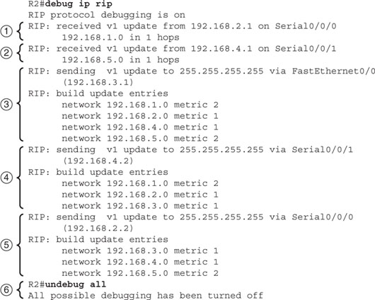
This command displays RIP routing updates as they are sent and received, which allows you the opportunity to track down potential sources of a routing problem. The list that follows corresponds to the numbers in Figure 14-5.
-
You see an update coming in from R1 on interface Serial 0/0/0. Notice that R1 sends only one route to the 192.168.1.0 network. No other routes are sent, because doing so would violate the split horizon rule. R1 is not allowed to advertise networks back to R2 that R2 previously sent to R1.
-
The next update that is received is from R3. Again, because of the split horizon rule, R3 sends only one route: the 192.168.5.0 network.
-
R2 sends out its own updates. First, R2 builds an update to send out the FastEthernet 0/0 interface. The update includes the entire routing table except for network 192.168.3.0, which is attached to FastEthernet 0/0.
-
Next, R2 builds an update to send to R3. Three routes are included. R2 does not advertise the network R2 and R3 share, nor does it advertise the 192.168.5.0 network because of split horizon.
-
Finally, R2 builds an update to send to R1. Three routes are included. R2 does not advertise the network that R2 and R1 share, nor does it advertise the 192.168.1.0 network because of split horizon.
-
To stop monitoring RIP updates on R2, enter the no debug ip rip command or undebug all, as shown in the figure.
Passive Interfaces
In the topology shown in Figure 14-3, notice that there is no reason to send updates out the Fast Ethernet interfaces on any of the routers. Therefore, you should configure these as passive interfaces for two reasons:
![]() Enhance security by preventing someone attached to one of the LANs from intercepting, inspecting, and possibly modifying the RIP updates.
Enhance security by preventing someone attached to one of the LANs from intercepting, inspecting, and possibly modifying the RIP updates.
![]() Improve the efficiency of the routers’ processing.
Improve the efficiency of the routers’ processing.
Use the passive-interface interface-type interface-number command to stop sending RIP updates out the Fast Ethernet interfaces, as shown in Example 14-13 for R2. The show ip protocols command is then used to verify the passive interface configuration.
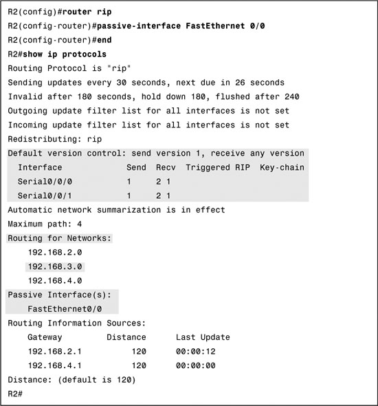
Notice that the interface is no longer listed under Interface but under a new section called Passive Interface(s). Also notice that the network 192.168.3.0 is still listed under Routing for Networks:, which means that this network is still included as a route entry in RIP updates that are sent to R1 and R3. All routing protocols support the passive-interface command.
Automatic Summarization
RIP automatically summarizes at the classful network boundary. Figure 14-6 and Table 14-4 shows the RIPv1 topology for Scenario B and the addressing scheme we will use for the remainder of our RIPv1 review.
Assuming all interfaces are configured and activated, Example 14-14 shows the RIP configuration for R1, R2, and R3.
Example 14-14 RIPv1 Standard Configuration: Scenario B
R1(config)#router rip
R1(config-router)#network 172.30.0.0
_____________________________________
R2(config)#router rip
R2(config-router)#network 172.30.0.0
R2(config-router)#network 192.168.4.0
_____________________________________
R3(config)#router ip
R3(config-router)#network 192.168.4.0
R3(config-router)#network 192.168.5.0
Notice in the RIP configuration for all routers, the classful network address was entered instead of each subnet. If we had entered the subnets instead, Cisco IOS would have summarized them to the classful network address. This is because a RIP router either uses the subnet mask configured on a local interface or applies the default subnet mask based on the address class. Therefore, RIPv1 cannot support discontiguous subnets, supernets, or VLSM addressing schemes. Example 14-15 shows what R2 sends in its updates to R1 and R3.
Example 14-15 R2 RIPv1 Updates
R2#debug ip rip
RIP protocol debugging is on
RIP: sending v1 update to 255.255.255.255 via Serial0/0/0 (172.30.2.2)
RIP: build update entries
network 172.30.3.0 metric 1
network 192.168.4.0 metric 1
network 192.168.5.0 metric 2
RIP: sending v1 update to 255.255.255.255 via Serial0/0/1 (192.168.4.9)
RIP: build update entries
network 172.30.0.0 metric 1
When R2 sends updates to R1, it sends the 172.30.3.0 network because the Serial 0/0/0 interface is using a /24 mask for the 172.30.2.0 network. However, it summarizes the 192.168.4.8 subnet to 192.168.4.0 before sending the update to R1 because R1 will apply the default classful mask to the routing update. R2 is a boundary router for the 192.168.4.0 network. For its update to R3, R2 summarizes subnets 172.30.1.0, 172.30.2.0, and 172.30.3.0 to the classful network 172.30.0.0 because R2 is the boundary router for the 172.30.0.0 network and assumes R3 does not have any other way to get to the 172.30.0.0 network.
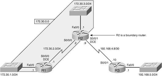
Default Routing and RIPv1
Using the same addressing scheme from Table 14-4, let’s modify the topology as shown in Figure 14-7 so that R2 and R3 are using static and default routing.

Example 14-16 shows the configuration changes made to R2 and R3. R3 is providing service to the Internet. So R2 will use a default route to send all traffic for unknown destination to R3. R3 will use a summary route to send all traffic to the 172.30.0.0 subnets.
Example 14-16 Configuration Changes to R2 and R3
R2(config)#router rip
R2(config-router)#no network 192.168.4.0
R2(config-router)#exit
R2(config)#ip route 0.0.0.0 0.0.0.0 serial 0/0/1
_________________________________________________________
R3(config)#no router rip
R3(config)#ip route 172.30.0.0 255.255.252.0 serial 0/0/1
We could configure R1 with a default route pointing to R2. But a better and more scalable solution is to use the default-information originate command to have R2 propagate its default route to R1 in its RIP routing updates.
R2(config)#router rip
R2(config-router)#default-information originate
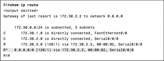
As shown in Example 14-17, R1 now has a RIP route tagged with the asterisk (*) code indicating that this route is a default gateway.
RIPv2 Configuration
Like Version 1, RIPv2 is encapsulated in a UDP segment using port 520 and can carry up to 25 routes. Figure 14-8 shows the RIPv1 and RIPv2 message formats.
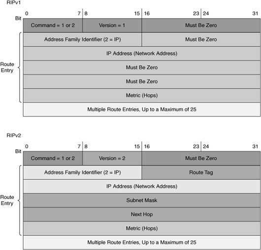
For review purposes, the most important extension RIPv2 provides in the addition of the subnet mask field, which allows a 32-bit mask to be included in the RIP route entry. As a result, the receiving router no longer depends on the subnet mask of the inbound interface or the classful mask when determining the subnet mask for a route. This means that RIPv1’s three main limitations—lack of discontiguous network designs, supernetting, and VLSM support—are no longer an issue.
By default, the RIP process on Cisco routers sends RIPv1 messages but can receive both RIPv1 and RIPv2. You can see this in the show ip protocols output shown previously in Example 14-13. To enable the sending of RIPv2 messages in our topology, enter the command version 2 in router configuration mode, as demonstrated in Example 14-18.

With this configuration, R2 will now send and receive only RIPv2 messages. That means we must configure R1 with the version 2 command as well because R2 will ignore the RIPv1 messages sent by R1.
Disabling Autosummarization
Notice the line in the show ip protocols output from Example 14-18 that states:
Automatic network summarization is in effect
By default, RIPv2 automatically summarizes networks to the classful boundary just like RIPv1. So, to support discontiguous subnets and VLSM, you must first disable automatic summarization with the no auto-summary command on all RIPv2 routers to ensure that individual subnets are sent in routing updates—not the classful network address.
RIPv2 Verification and Troubleshooting
There are several ways to verify and troubleshoot RIPv2. You can use many of the same commands for RIPv2 to verify and troubleshoot other routing protocols. It is always best to begin with the basics:
![]() Make sure that all the links (interfaces) are up and operational.
Make sure that all the links (interfaces) are up and operational.
![]() Check the cabling.
Check the cabling.
![]() Make sure that you have the correct IP address and subnet mask on each interface.
Make sure that you have the correct IP address and subnet mask on each interface.
![]() Remove any configuration commands that are no longer necessary or have been replaced by other commands.
Remove any configuration commands that are no longer necessary or have been replaced by other commands.
Commands to use are the same as for RIPv1 as well as your standard use of show ip interface brief, show run, and ping. But also consider the following RIPv2 specific issues:
![]() Version: A good place to begin troubleshooting a network that is running RIP is to verify that the version 2 command is configured on all routers. RIPv1 does not support discontiguous subnets, VLSM, or CIDR supernet routes.
Version: A good place to begin troubleshooting a network that is running RIP is to verify that the version 2 command is configured on all routers. RIPv1 does not support discontiguous subnets, VLSM, or CIDR supernet routes.
![]() Network statements: Another source of problems might be incorrectly configured or missing network statements configured with the network command. Remember, the network command does two things:
Network statements: Another source of problems might be incorrectly configured or missing network statements configured with the network command. Remember, the network command does two things:
— It enables the routing protocol to send and receive updates on any local interfaces that belong to that network.
— It includes the configured network in its routing updates to its neighboring routers.
A missing or incorrect network statement will result in missed routing updates and routing updates not being sent or received on an interface.
![]() Automatic summarization: If there is a need or expectation for sending specific subnets and not just summarized routes, make sure that automatic summarization has been disabled with the no auto-summary command.
Automatic summarization: If there is a need or expectation for sending specific subnets and not just summarized routes, make sure that automatic summarization has been disabled with the no auto-summary command.