Day 16 Basic Router Configuration and Verification
CCNA 640-802 Exam Topics
![]() Access and utilize the router to set basic parameters (CLI/SDM).
Access and utilize the router to set basic parameters (CLI/SDM).
![]() Connect, configure, and verify operation status of a device interface.
Connect, configure, and verify operation status of a device interface.
![]() Implement basic router security.
Implement basic router security.
![]() Verify device configuration and network connectivity using ping, traceroute, telnet, SSH, or other utilities.
Verify device configuration and network connectivity using ping, traceroute, telnet, SSH, or other utilities.
![]() Verify network connectivity (using ping, traceroute, and telnet or SSH).
Verify network connectivity (using ping, traceroute, and telnet or SSH).
Key Topic
Today we review the basic router configuration and verification commands as well as testing using the ping, traceroute, and telnet commands. Most of this should be very familiar to you at this point in your studies because these skills are fundamental to all other router configuration tasks.
Note Cisco Security Device Manager (SDM) is a GUI-based method to access and configure the router. Reviewing SDM here would take up too much space because we would need to repeat dozens of screenshots. So for your SDM review today, refer to your Study Resources. Each has an extensive review of basic router configuration using SDM.
Basic Router Configuration
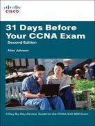
Figure 16-1 shows the topology and addressing scheme we will use to review basic router configuration and verification tasks.
When configuring a router, certain basic tasks are performed, including the following:
![]() Naming the router
Naming the router
![]() Setting passwords
Setting passwords
![]() Configuring interfaces
Configuring interfaces
![]() Configuring a banner
Configuring a banner
![]() Saving changes on a router
Saving changes on a router
![]() Verifying basic configuration and router operations
Verifying basic configuration and router operations
Table 16-1 shows the basic router configuration command syntax used to configure R1 in the following example.

Let’s walk through a basic configuration for R1. First, we enter privileged EXEC mode and then we enter global configuration mode:
Router>enable
Router#config t
Next, name the router and enter the encrypted password for entering privileged EXEC mode. This command overrides the older enable password password command so we are not entering that one:
Router(config)#hostname R1
R1(config)#enable secret class
Next, configure the console password and require it be entered with the login password:
R1(config)#line console 0
R1(config-line)#password cisco
R1(config-line)#login
Then configure the password for the Telnet lines and require it to be entered with the login password:
R1(config)#line vty 0 4
R1(config-line)#password cisco
R1(config-line)#login
Configure the message-of-the-day (MOTD) banner. A delimiting character such as a # is used at the beginning and at the end of the message. At a minimum, a banner should warn against unauthorized access. A good security policy would prohibit configuring a banner that “welcomes” an unauthorized user:
R1(config)#banner motd #
Enter TEXT message. End with the character '#'.
******************************************
WARNING!! Unauthorized Access Prohibited!!
******************************************
#
Now configure the individual router interfaces with IP addresses and other information. First, enter interface configuration mode by specifying the interface type and number. Next, configure the IP address and subnet mask:
R1(config)#interface Serial0/0/0
R1(config-if)#ip address 192.168.2.1 255.255.255.0
It is good practice to configure a description on each interface to help document the network information:
R1(config-if)#description Ciruit#VBN32696-123 (help desk:1-800-555-1234)
Activate the interface:
R1(config-if)#no shutdown
In a lab environment, we add a clock rate on the DCE side. However, in production environments the service provider sets the clock:
R1(config-if)#clock rate 64000
Assuming the other side of the link is activated on R2, the serial interface will now be up. Finish R1 by configuring the FastEthernet 0/0 interface:
R1(config-if)#interface FastEthernet0/0
R1(config-if)#ip address 192.168.1.1 255.255.255.0
R1(config-if)#description R1 LAN
R1(config-if)#no shutdown
Assume R2 is fully configured and can route back to the 192.168.1.0/24 LAN attached to R1. We need to add a static route to R1 to ensure connectivity to R2’s LAN. Static routing is reviewed in more detail on Day 14. For now, enter the following command:
R1(config)#ip route 192.168.3.0 255.255.255.0 192.168.2.2
To save the configuration, enter the copy running-config startup-config command or copy run start.
You can use the show running-config command to verify the full current configuration on the router; however, a few other basic commands can help you not only verify your configuration, but help you begin troubleshooting any potential problems.
First, make sure the networks for your interfaces are now in the routing table by using the show ip route command, as demonstrated in Example 16-1.

If a network is missing, check your interface status with the show ip interface brief command, as demonstrated in Example 16-2.

The output from the show ip interface brief command provides you with three important pieces of information:
![]() IP address
IP address
![]() Line Status (column 5)
Line Status (column 5)
![]() Protocol Status (column 6)
Protocol Status (column 6)
The IP address should be correct, and the interface status should be “up” and “up”. Table 16-2 summarizes the two status codes and their meanings.

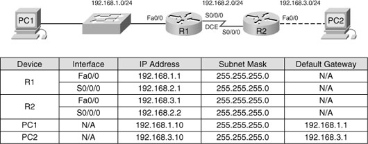
Four combinations of settings exist for the status codes when troubleshooting a network. Table 16-3 lists the four combinations, along with an explanation of the typical reasons why an interface would be in that state.
If necessary, use the more verbose show interfaces command if you need to track down a problem with an interface. Example 16-3 shows the output for FastEthernet 0/0.
Example 16-3 The show interfaces Command
R1#show interfaces fastethernet 0/0
FastEthernet0/0 is up, line protocol is up (connected)
Hardware is Lance, address is 0007.eca7.1511 (bia 00e0.f7e4.e47e)
Description: R1 LAN
Internet address is 192.168.1.1/24
MTU 1500 bytes, BW 100000 Kbit, DLY 100 usec, rely 255/255, load 1/255
Encapsulation ARPA, loopback not set
ARP type: ARPA, ARP Timeout 04:00:00,
Last input 00:00:08, output 00:00:05, output hang never
Last clearing of "show interface" counters never
Queueing strategy: fifo
Output queue :0/40 (size/max)
5 minute input rate 0 bits/sec, 0 packets/sec
5 minute output rate 0 bits/sec, 0 packets/sec
81833 packets input, 27556491 bytes, 0 no buffer
Received 0 broadcasts, 0 runts, 0 giants, 0 throttles
1 input errors, 0 CRC, 0 frame, 0 overrun, 1 ignored, 0 abort
0 input packets with dribble condition detected
55794 packets output, 3929696 bytes, 0 underruns
0 output errors, 0 collisions, 1 interface resets
0 babbles, 0 late collision, 4 deferred
0 lost carrier, 0 no carrier
0 output buffer failures, 0 output buffers swapped out
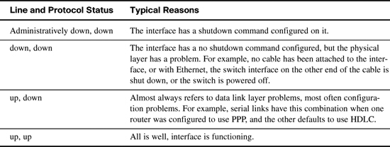
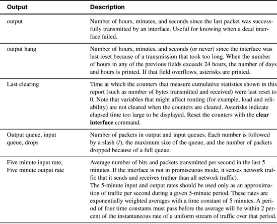
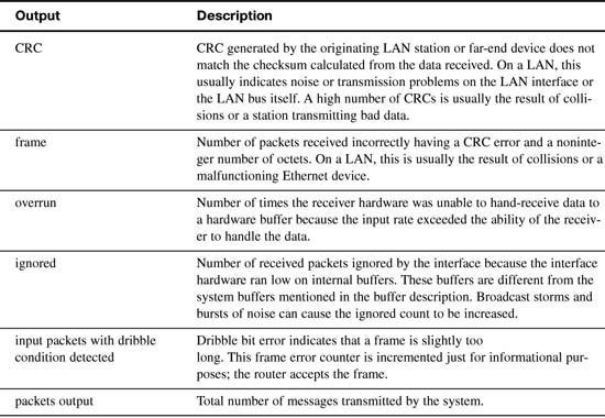
This command has a lot of output. However, sometimes this is the only way to find a problem. Therefore, Table 16-4 parses and explains each important part of the show interfaces output.


Verifying Network Connectivity
As reviewed on Day 20, “Host Addressing, DHCP, and DNS,” ping and traceroute are helpful tools for verifying network connectivity. These tools work for routers as well. The only difference is the command output and the command syntax.
Example 16-4 demonstrates successful ping output on the router.
Unsuccessful ping output shows periods (.) instead of exclamation points (!) as demonstrated in Example 16-5.
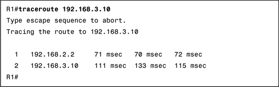
When tracing the route to the destination, use the command traceroute on a router instead of the tracert command used on a Windows PC. Example 16-6 shows output from a successful traceroute command.
Unsuccessful traces will show the last successful hop and the asterisks for each attempt until the user cancels. To cancel the traceroute command on a router, use the key combination Ctrl+Shift+6, and then the x key. Example 16-7 shows unsuccessful traceroute output.

Using Telnet or SSH to remotely access another device also tests connectivity. More importantly, these remote access methods will test whether a device has been correctly configured so that you can access it for management purposes. This can be very important when a device is truly remote (for example, across town or in another city). Day 8, “Switching Technologies and VLAN Concepts,” reviews SSH configuration and verification in greater detail.
During our basic configuration tasks earlier, we entered the commands to properly configure the Telnet lines (vty 0 4) for remote access. Example 16-8 shows a success Telnet from R1 to R2.
If R2 does not have a password configured, you might see the following output shown in Example 16-9.