Day 23 VLAN and Trunking Configuration and Troubleshooting
CCNA 640-802 Exam Topics
![]() Configure, verify, and troubleshoot VLANs
Configure, verify, and troubleshoot VLANs
![]() Configure, verify, and troubleshoot trunking on Cisco switches
Configure, verify, and troubleshoot trunking on Cisco switches
Key Points
The following sections present a sample topology and the commands to configure, verify, and troubleshoot VLANs and trunking. The review for today is brief so that you can spend your time practicing your configuration, verification, and troubleshooting skills.
Sample Topology
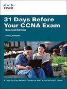
For today’s exam topics, we will use the topology shown in Figure 23-1 to review the commands for configuring, verifying, and troubleshooting VLAN and trunking. I strongly recommend that you build and configure this topology—either using real equipment or a network simulator—as part of your review for the CCNA exam.
VLAN Configuration and Verification Commands
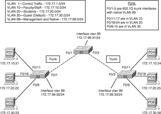
The default configuration of a Cisco switch is to put all interfaces in VLAN 1, which can be verified with the show vlan brief command, as demonstrated for S2 in Example 23-1.
A VLAN can be created in one of two ways: either in global configuration mode or directly under the interface. The advantage to configuring in global configuration mode is that you can then assign a name with the name vlan-name command. The advantage to configuring the VLAN in interface configuration mode is that you assign the VLAN to the interface and create the VLAN with just one command. However, to name the VLAN, you still have to go back to the global configuration method. Example 23-2 shows the creation of VLANs 10 and 20 using these two methods. VLAN 20 is then named, and the remaining VLANs are created in global configuration mode.
Example 23-2 Creating VLANs
S2#config t
Enter configuration commands, one per line. End with CNTL/Z.
S2(config)#vlan 10
S2(config-vlan)#name Faculty/Staff
S2(config-vlan)#interface fa 0/18
S2(config-if)#switchport access vlan 20
% Access VLAN does not exist. Creating vlan 20
S2(config-if)#vlan 20
S2(config-vlan)#name Students
S2(config-vlan)#vlan 30
S2(config-vlan)#name Guest(Default)
S2(config-vlan)#vlan 99
S2(config-vlan)#name Management&Native
S2(config-vlan)#end
%SYS-5-CONFIG_I: Configured from console by console
S2#
Notice in Example 23-3 that all the VLANs are created. But only VLAN 20 is assigned to an interface.

To assign the remaining interfaces to the VLANs specified in Figure 23-1, you can configure one interface at a time, or you can use the range command to configure all the interfaces that belong to a VLAN with one command, as shown in Example 23-4.
Example 23-4 Assigning VLANs to Interfaces
S2#config t
Enter configuration commands, one per line. End with CNTL/Z.
S2(config)#interface range fa 0/11 - 17
S2(config-if-range)#switchport access vlan 10
S2(config-if-range)#interface range fa 0/18 - 24
S2(config-if-range)#switchport access vlan 20
S2(config-if-range)#interface range fa 0/6 - 10
S2(config-if-range)#switchport access vlan 30
S2(config-if-range)#end
%SYS-5-CONFIG_I: Configured from console by console
S2#
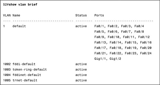
The show vlan brief command in Example 23-5 verifies that all interfaces specified in Figure 23-1 have been assigned to the appropriate VLAN. Notice that unassigned interfaces still belong to the default VLAN 1.
You can also verify a specific interface’s VLAN assignment with the show interfaces type number switchport command, as shown for FastEthernet 0/11 in Example 23-6.
Example 23-6 Verifying an Interface’s VLAN Assignment
S2#show interfaces fastethernet 0/11 switchport
Name: Fa0/11
Switchport: Enabled
Administrative Mode: dynamic auto
Operational Mode: static access
Administrative Trunking Encapsulation: dot1q
Operational Trunking Encapsulation: native
Negotiation of Trunking: On
Access Mode VLAN: 10 (Faculty/Staff)
Trunking Native Mode VLAN: 1 (default)
Voice VLAN: none
Administrative private-vlan host-association: none
Administrative private-vlan mapping: none
Administrative private-vlan trunk native VLAN: none
Administrative private-vlan trunk encapsulation: dot1q
Administrative private-vlan trunk normal VLANs: none
Administrative private-vlan trunk private VLANs: none
Operational private-vlan: none
Trunking VLANs Enabled: ALL
Pruning VLANs Enabled: 2-1001
Capture Mode Disabled
Capture VLANs Allowed: ALL
Protected: false
Appliance trust: none
S2#
For the sample topology shown in Figure 23-1, you would configure the VLANs on S1 and S3 as well, but only S3 needs VLANs assigned to interfaces.
Configuring and Verifying Trunking
Following security best practices, we are configuring a different VLAN for the management and default VLAN. In a production network, you would want to use a different one for each: one for the management VLAN and one for the native VLAN. However, for expediency we are using VLAN 99 for both.
To begin, we must first define a new management interface for VLAN 99, as shown in Example 23-7.
Example 23-7 Defining a New Management Interface
S1#config t
Enter configuration commands, one per line. End with CNTL/Z.
S1(config)#interface vlan 99
%LINK-5-CHANGED: Interface Vlan99, changed state to up
S1(config-if)#ip address 172.17.99.31 255.255.255.0
S1(config-if)#end
%SYS-5-CONFIG_I: Configured from console by console
S1#
Repeat the configuration on S2 and S3. The IP address is used for testing connectivity to the switch as well as the IP address the network administrator uses for remote access (Telnet, SSH, SDM, HTTP, etc.).
Depending on the switch model and IOS version, DTP may have already established trunking between two switches that are directly connected. For example, the default trunk configuration for 2950 switches is dynamic desirable. Therefore, a 2950 will initiate trunk negotiations. For our purposes, we will assume the switches are all 2960s. The 2960 default trunk configuration is dynamic auto, in which the interface will not initiate trunk negotiations.
In Example 23-8, the first five interfaces on S1 are configured for trunking. Also, notice that the native VLAN is changed to VLAN 99.
Example 23-8 Trunk Configuration and Native VLAN Assignment
S1#config t
Enter configuration commands, one per line. End with CNTL/Z.
S1(config)#interface range fa0/1 - 5
S1(config-if-range)#switchport mode trunk
S1(config-if-range)#switchport trunk native vlan 99
S1(config-if-range)#end
%SYS-5-CONFIG_I: Configured from console by console
S1#
%CDP-4-NATIVE_VLAN_MISMATCH: Native VLAN mismatch discovered on FastEthernet0/1
(99), with S2 FastEthernet0/1 (1).
%CDP-4-NATIVE_VLAN_MISMATCH: Native VLAN mismatch discovered on FastEthernet0/3
(99), with S3 FastEthernet0/3 (1).
If you wait for the next round of CDP messages, you should get the error message shown in Example 23-8. Although the trunk is working between S1 and S2 and between S1 and S3, the switches do not agree on the native VLAN. Repeat the trunking commands on S2 and S3 to correct the native VLAN mismatch.
Note The encapsulation type—dot1q or isl—might need to be configured depending on the switch model. If so, the syntax for configuring the encapsulation type is as follows:
Switch(config-if)#switchport trunk encapsulation { dot1q | isl | negotiate }
The 2960 series supports only 802.1Q, so this command is not available.
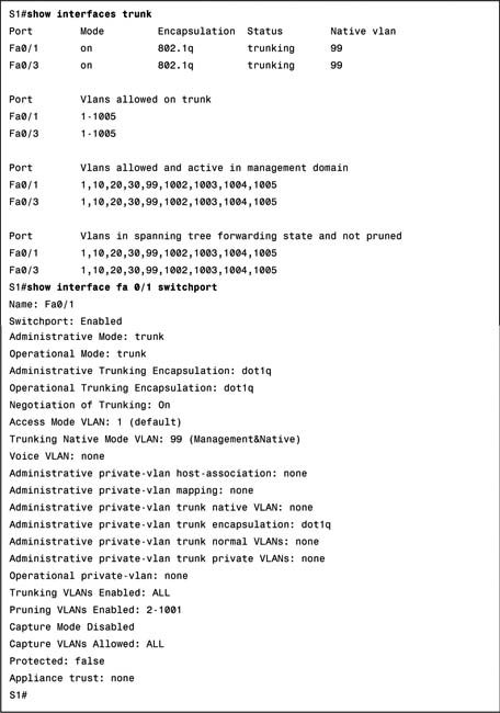
To verify that trunking is operational, use the commands shown in Example 23-9.
Remember, hosts on the same VLAN must be configured with an IP address and subnet mask on the same subnet. So the ultimate test of your configuration is to verify that end devices on the same VLAN can now ping each other. If not, use the verification commands to systematically track down the problem with your configuration, as discussed in the next section.
Troubleshooting VLAN and Trunking Problems
In Wendell Odom’s book, CCNA ICND2 Official Exam Certification Guide Second Edition, he details a methodology for troubleshooting a switched network from the physical layer up to and including VLAN and trunk configurations. Although today we are focusing on VLAN and trunk configuration, verification, and troubleshooting, a quick review of troubleshooting other switch problems is included in this very brief summary of the steps delineated by Odom.
Step 1 Confirm the network diagram using CDP.
Network diagrams are often outdated or incomplete. Use the CDP commands show cdp neighbors and show cdp neighbors detail to gain more information about directly connected neighbors.
Step 2 Isolate interface problems.
a. Determine interface status code(s) for each required interface, and if not in a connect or up/up state, resolve the problems until the interface reaches the connect or up/up state.
b. For interfaces in a connect (up/up) state, also check for two other problems: duplex mismatches and some variations of port security purposefully dropping frames.
Helpful commands include show interfaces and show interfaces status.
Step 3 Isolate filtering and port security problems.
a. Identify all interfaces on which port security is enabled (show running-config or show port-security).
b. Determine whether a security violation is currently occurring based in part on the violation mode of the interface’s port security configuration, as follows:
— shutdown: The interface will be in an err-disabled state.
— restrict: The interface will be in a connect state, but the show portsecurity interface command will show an incrementing violations counter.
— protect: The interface will be in a connect state, and the show portsecurity interface command will not show an incrementing violations counter.
c. In all cases, compare the port security configuration to the diagram as well as the “last source address” field in the output of the show portsecurity interface command.
Step 4 Isolate VLAN and trunking problems.
a. Identify all access interfaces and their assigned access VLANs, and reassign into the correct VLANs as needed.
b. Determine whether the VLANs both exist (configured or learned with VTP) and are active on each switch. If not, configure and activate the VLANs to resolve problems as needed.
c. Identify the operationally trunking interfaces on each switch, and determine the VLANs that can be forwarded over each trunk.