Day 22 VTP and InterVLAN Routing Configuration and Troubleshooting
CCNA 640-802 Exam Topics
![]() Configure, verify, and troubleshoot VTP.
Configure, verify, and troubleshoot VTP.
![]() Configure, verify, and troubleshoot inter-VLAN routing.
Configure, verify, and troubleshoot inter-VLAN routing.
Key Points
Today we review the commands and tasks necessary to configure, verify, and troubleshoot VLAN Trunking Protocol (VTP). Also, we review inter-VLAN routing and router commands for a router-on-a-stick implementation.
VTP Configuration and Verification
VTP is a Layer 2 messaging protocol that maintains VLAN configuration consistency by managing the additions, deletions, and name changes of VLANs across networks. This section uses the sample topology in Figure 22-1, which is the same topology used for Day 23. You should build and configure this topology as part of your review for the CCNA exam.

After choosing which switch will be the server and which switches will be clients, use the following steps to configure VTP:
Step 1 Configure the VTP mode using the vtp mode {server | client} global configuration command.
Step 2 (Optional, but recommended) On both clients and servers, configure the same case-sensitive password using the vtp password password-value global configuration command.
Step 3 Configure the VTP (case-sensitive) domain name using the vtp domain domain-name global configuration command.
Step 4 (Optional) Configure VTP pruning on the VTP servers using the vtp pruning global configuration command.
Step 5 (Optional) Enable VTP version 2 with the vtp version 2 global configuration command.
Step 6 Bring up trunks between the switches.
Before configuring VTP, look at the default VTP state of S1. To do so, use the command show vtp status as shown in Example 22-1.
Example 22-1 Default VTP Configuration on S1
S1#show vtp status
VTP Version : 2
Configuration Revision : 0
Maximum VLANs supported locally : 64
Number of existing VLANs : 5
VTP Operating Mode : Server
VTP Domain Name :
VTP Pruning Mode : Disabled
VTP V2 Mode : Disabled
VTP Traps Generation : Disabled
MD5 digest : 0x7D 0x5A 0xA6 0x0E 0x9A 0x72 0xA0 0x3A
Configuration last modified by 0.0.0.0 at 0-0-00 00:00:00
Local updater ID is 0.0.0.0 (no valid interface found)
Notice the configuration revision number is 0 and that the number of existing VLANs is 5—the five default VLANs that always exist on the switch. Also notice that S1 is already a VTP server.
The commands in Example 22-2 configure S1 as the server using cisco as the VTP password and CCNA as the VTP domain name. Because S2 and S3 share all the same VLANs, we are not configuring VTP pruning (enabled globally with the command vtp pruning). We will also leave VTP in the default version 1 mode (enabled globally with the command vtp version 2).
Example 22-2 Configuring the VTP Server
S1#config t
Enter configuration commands, one per line. End with CNTL/Z.
S1(config)#vtp mode server
Device mode already VTP SERVER.
S1(config)#vtp password cisco
Setting device VLAN database password to cisco
S1(config)#vtp domain CCNA
Changing VTP domain name from NULL to CCNA
S1(config)#end
%SYS-5-CONFIG_I: Configured from console by console
S1#
Note We configured the VTP password before the VTP domain name for a specific reason. As soon as the VTP domain name is configured, S1 will begin sending out VTP messages on all trunk links that are active. If switches on the other end of the trunk are using the default VTP configuration (server mode, null as the domain name, and no password), they will start using the domain name sent in the VTP messages. This can cause VLAN database corruption if the receiving switch has a higher configuration revision number than the configured server. The receiving switch is also a VTP server and will send out its VLAN database to the configured VTP server. By configuring the password first, we avoid the potential for this to happen. After the switches on the other end of the trunks are configured as clients, their configuration revision number is reset to 0. Then when the domain name and password are configured, VTP updates will be requested from the VTP server.
We explicitly configured S1 as a VTP server instead of assuming it is in the default VTP server mode. Example 22-3 shows the commands used to verify the configuration.
Example 22-3 Verifying the VTP Configuration
S1#show vtp status
VTP Version : 2
Configuration Revision : 0
Maximum VLANs supported locally : 64
Number of existing VLANs : 5
VTP Operating Mode : Server
VTP Domain Name : CCNA
VTP Pruning Mode : Disabled
VTP V2 Mode : Disabled
VTP Traps Generation : Disabled
MD5 digest : 0x8C 0x29 0x40 0xDD 0x7F 0x7A 0x63 0x17
Configuration last modified by 0.0.0.0 at 0-0-00 00:00:00
Local updater ID is 0.0.0.0 (no valid interface found)
S1#show vtp password
VTP Password: cisco
S1#
Example 22-4 shows the commands to configure S2 as a client with the same password and domain name as S1. Repeat the same commands on S3.
Example 22-4 Configure the VTP Clients
S2#config t
Enter configuration commands, one per line. End with CNTL/Z.
S2(config)#vtp mode client
Setting device to VTP CLIENT mode.
S2(config)#vtp password cisco
Setting device VLAN database password to cisco
S2(config)#vtp domain CCNA
Changing VTP domain name from NULL to CCNA
S2(config)#end
%SYS-5-CONFIG_I: Configured from console by console
S2#
Again, verify the configuration with the show vtp status and show vtp password commands.
At this point, configure the VLANs on the VTP server, S1. You will not be able to create VLANs on S2 or S3. If you try, you will get the following console message:
S3(config)#vlan 10
VTP VLAN configuration not allowed when device is in CLIENT mode.
S3(config)#
Remember, however, that on the client switches you will still be able to assign switch ports to specific VLANs.
After configuring the VLANs, notice that the configuration revision number is incremented for each modification to the VLAN database. If you made no errors in your configuration, the configuration revision number should be 8, as shown in Example 22-5—one increment for each time you added one of the four VLANs and one increment for each time you named one of the VLANs. There are now a total of nine VLANs on the server.

S2 and S3 have not received the VLANs yet because the trunks are not active between the switches and S1. In this case, configure the appropriate S1 interfaces to trunk and assign VLAN 99 as the native VLAN. In some cases, DTP will autonegotiate the trunk links on S2 and S3. Now both client switches should have received VTP advertisements for S1. As shown in Example 22-6, both S2 and S3 have synchronized VLAN databases.
Example 22-6 Verifying S2 and S3 Now Have Synchronized VLAN Databases
S2#show vtp status
VTP Version : 2
Configuration Revision : 8
Maximum VLANs supported locally : 64
Number of existing VLANs : 9
VTP Operating Mode : Client
VTP Domain Name : CCNA
VTP Pruning Mode : Disabled
VTP V2 Mode : Disabled
VTP Traps Generation : Disabled
MD5 digest : 0x43 0x68 0xD5 0x3B 0x58 0x79 0x68 0x0E
Configuration last modified by 172.17.99.31 at 3-1-93 00:33:01
S2#
S3#show vtp status
VTP Version : 2
Configuration Revision : 8
Maximum VLANs supported locally : 64
Number of existing VLANs : 9
VTP Operating Mode : Client
VTP Domain Name : CCNA
VTP Pruning Mode : Disabled
VTP V2 Mode : Disabled
VTP Traps Generation : Disabled
MD5 digest : 0x43 0x68 0xD5 0x3B 0x58 0x79 0x68 0x0E
Configuration last modified by 172.17.99.31 at 3-1-93 00:33:01
S3#
Note Although configuring VTP does help manage the VLAN configuration in your networks, it is not required to create VLANs. In addition, VTP does not assign VLANs to switch ports. You must manually assign VLANs to switch ports on each switch.
To avoid using VTP on a switch, configure it to use transparent mode:
Switch(config)#vtp mode transparent
The switch will not update its VLAN database from VTP messages but will still forward the VTP messages out trunk interfaces. In addition, you can configure local VLANs on a switch in VTP transparent mode.
VTP Troubleshooting
Although VTP provides a level of efficiency to your switched network by allowing you to configure your VLAN database on a VTP server, VTP also has the potential to cause serious problems. To combat the misuse of VTP in production networks, Cisco created the following training tutorial on Cisco.com, which you should review as part of your preparation for the CCNA exam:
http://www.cisco.com/warp/public/473/vtp_flash/
The following steps are a systematic way to determine why VTP is not currently working as expected.
Step 1 Confirm the switch names, topology (including which interfaces connect which switches), and switch VTP modes.
Step 2 Identify sets of two neighboring switches that should be either VTP clients or servers whose VLAN databases differ with the show vlan command.
Step 3 On each pair of two neighboring switches whose databases differ, verify the following:
a. At least one operational trunk should exist between the two switches (use the show interfaces trunk, show interfaces switchport, or show cdp neighbors command).
b. The switches must have the same (case-sensitive) VTP domain name (show vtp status).
c. If configured, the switches must have the same (case-sensitive) VTP password (show vtp password).
d. Although VTP pruning should be enabled or disabled on all servers in the same domain, having two servers configured with opposite pruning settings does not prevent the synchronization process.
Step 4 For each pair of switches identified in Step 3, solve the problem by either troubleshooting the trunking problem or reconfiguring a switch to correctly match the domain name or password.
To avoid the potential for VTP problems, implement the following best practices.
![]() Reset the configuration revision number before installing a new switch. This can be done in one of the following ways:
Reset the configuration revision number before installing a new switch. This can be done in one of the following ways:
— Change the switch to VTP transparent mode.
— Change the domain name to something other than the existing domain name.
— Delete the vlan.dat file and reload the switch.
![]() If you do not intend to use VTP at all, configure each switch to use transparent mode.
If you do not intend to use VTP at all, configure each switch to use transparent mode.
![]() If using VTP server or client mode, always use a VTP password.
If using VTP server or client mode, always use a VTP password.
![]() Prevent VTP attacks by disabling the potential for dynamic trunking negotiation on all interfaces except known trunks with either the switchport mode access or switchport nonegotiate commands.
Prevent VTP attacks by disabling the potential for dynamic trunking negotiation on all interfaces except known trunks with either the switchport mode access or switchport nonegotiate commands.
Inter-VLAN Routing Configuration and Verification
Cisco switches support two trunking protocols: Inter-Switch Link (ISL) and IEEE 802.1Q. Cisco created ISL many years before the IEEE created the 802.1Q standard VLAN trunking protocol. Because ISL is Cisco proprietary, it can be used only between two Cisco switches that support ISL. ISL fully encapsulates each original Ethernet frame in an ISL header and trailer.
Years after Cisco created ISL, the IEEE completed work on the 802.1Q standard, which defines a different way to do trunking. Today, 802.1Q has become the more popular trunking protocol, with Cisco not even supporting ISL in some of its newer models of LAN switches, including the 2960 switches used in the examples in this book. 802.1Q does not actually encapsulate the original frame in another Ethernet header and trailer. Instead, 802.1Q inserts an extra 4-byte VLAN header into the original frame’s Ethernet header. For more details on the differences and similarities between ISL and 802.1Q, see your study resources.
Configuring inter-VLAN routing is pretty straightforward. Refer to the sample topology shown in Figure 22-2 to review the commands.

This router-on-a-stick topology is configured using the following steps on the router:
Step 1 Activate the physical interface that is trunking with the switch using the no shutdown command.
Step 2 Enter subinterface configuration mode for the first VLAN that needs routing. One convention is to use the VLAN number as the subinterface number. For example, the command interface fa0/1.10 enters subinterface configuration mode for VLAN 10.
Step 3 Configure the trunking encapsulation type using the subinterface configuration command encapsulation {dot1q | isl} vlan-number [native]. Set the encapsulation—either dot1q or isl—to the type used by the switch. On some routers, the optional keyword native must be configured for the native VLAN before the router will route the native VLAN.
Step 4 Configure the IP address and subnet mask.
Step 5 Repeat Steps 2 through 4 for each additional VLAN that needs routing.
Assuming the switch is already configured with VLANs and trunking, Example 22-7 shows the commands to configure R1 to provide routing between VLAN 10 and VLAN 30.
Example 22-7 Configuring R1 to Route Between VLANs
R1#config t
Enter configuration commands, one per line. End with CNTL/Z.
R1(config)#interface fa0/0
R1(config-if)#no shutdown
R1(config-if)#interface fa0/1.10
R1(config-subif)#encapsulation dot1q 10
R1(config-subif)#ip add 172.17.10.1 255.255.255.0
R1(config-subif)#interface fa0/1.30
R1(config-subif)#encapsulation dot1q 30
R1(config-subif)#ip add 172.17.30.1 255.255.255.0
R1(config-subif)#
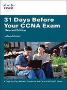
To verify the configuration, use the show ip route and show ip interface brief commands to make sure the new networks are in the routing table and the subinterfaces are “up” and “up” as shown in Example 22-8.
Assuming that the switch and PCs are configured correctly, the two PCs should now be able to ping each other. R1 will route the traffic between VLAN 10 and VLAN 30.
Troubleshooting Inter-VLAN Routing
To troubleshoot problems with inter-VLAN routing that are directly related to the router’s configuration, confirm the following:
![]() Is the physical cabling to the switch correct?
Is the physical cabling to the switch correct?
![]() Is the physical interface activated?
Is the physical interface activated?
![]() Is the encapsulation set to the right type?
Is the encapsulation set to the right type?
![]() Is the IP addressing correct?
Is the IP addressing correct?
If you answer “no” to any of these questions, isolate and correct the problem.