Day 13 EIGRP Routing
CCNA 640-802 Exam Topics
![]() Configure, verify, and troubleshoot EIGRP.
Configure, verify, and troubleshoot EIGRP.
Key Topics
Enhanced Interior Gateway Routing Protocol (EIGRP) is a distance vector, classless routing protocol that was released in 1992 with Cisco IOS Software Release 9.21. As its name suggests, EIGRP is an enhancement of the Interior Gateway Routing Protocol (IGRP). Both are Cisco proprietary protocols and operate only on Cisco routers. Today we review the operation, configuration, verification, and troubleshooting of EIGRP.
EIGRP Operation
EIGRP includes several features that are not commonly found in other distance vector routing protocols such as Routing Information Protocol (RIPv1 and RIPv2) and IGRP. These features include the following:
![]() Reliable Transport Protocol (RTP)
Reliable Transport Protocol (RTP)
![]() Bounded updates
Bounded updates
![]() Diffusing Update Algorithm (DUAL)
Diffusing Update Algorithm (DUAL)
![]() Establishing adjacencies
Establishing adjacencies
![]() Neighbor and topology tables
Neighbor and topology tables
Although EIGRP might act like a link-state routing protocol, it is still a distance vector routing protocol. Table 13-1 summarizes the main differences between a traditional distance vector routing protocol, such as RIP, and the enhanced distance vector routing protocol EIGRP.

EIGRP Message Format
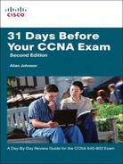
Figure 13-1 shows an example of an encapsulated EIGRP message.
Beginning from the right side of Figure 13-1, notice that the data field is called Type/Length/Value, or TLV. The types of TLVs relevant to the CCNA are EIGRP Parameters, IP Internal Routes, and IP External Routes.
The EIGRP packet header, shown in Figure 13-2, is included with every EIGRP packet, regardless of its TLV. The EIGRP packet header and TLV are then encapsulated in an IP packet. In the IP packet header, the protocol field is set to 88 to indicate EIGRP, and the destination address is set to the multicast address of 224.0.0.10. If the EIGRP packet is encapsulated in an Ethernet frame, the destination MAC address is also a multicast address: 01-00-5E-00-00-0A.

Important fields for our discussion include the Opcode field and the Autonomous System Number field. Opcode specifies the EIGRP packet type. The autonomous system number specifies the EIGRP routing process. Unlike RIP, Cisco routers can run multiple instances of EIGRP. The autonomous system number is used to track multiple instances of EIGRP.
RTP and EIGRP Packet Types
Reliable Transport Protocol (RTP) is the protocol used by EIGRP for the delivery and reception of EIGRP packets. EIGRP was designed as a network layer–independent routing protocol; therefore, it cannot use the services of UDP or TCP because IPX and AppleTalk do not use protocols from the TCP/IP protocol suite.
Although reliable is part of its name, RTP includes both reliable delivery and unreliable delivery of EIGRP packets. Reliable RTP requires an acknowledgment to be returned, whereas an unreliable RTP packet does not require an acknowledgment.
RTP can send packets either as a unicast or a multicast. Multicast EIGRP packets use the reserved multicast address of 224.0.0.10. EIGRP uses five packet types:
![]() Hello:: Hello packets are used by EIGRP to discover neighbors and to form adjacencies with those neighbors. EIGRP hello packets are multicasts and use unreliable delivery, so no response is required from the recipient. On most networks, EIGRP hello packets are sent every 5 seconds. On multipoint nonbroadcast multiaccess (NBMA) networks such as X.25, Frame Relay, and ATM interfaces with access links of T1 (1.544 Mbps) or slower, hellos are unicast every 60 seconds. By default, the hold time is 3 times the hello interval, or 15 seconds on most networks and 180 seconds on low-speed NBMA networks. If the hold time expires, EIGRP declares the route as down, and DUAL searches for a new path in the topology table or by sending out queries.
Hello:: Hello packets are used by EIGRP to discover neighbors and to form adjacencies with those neighbors. EIGRP hello packets are multicasts and use unreliable delivery, so no response is required from the recipient. On most networks, EIGRP hello packets are sent every 5 seconds. On multipoint nonbroadcast multiaccess (NBMA) networks such as X.25, Frame Relay, and ATM interfaces with access links of T1 (1.544 Mbps) or slower, hellos are unicast every 60 seconds. By default, the hold time is 3 times the hello interval, or 15 seconds on most networks and 180 seconds on low-speed NBMA networks. If the hold time expires, EIGRP declares the route as down, and DUAL searches for a new path in the topology table or by sending out queries.
![]() Update:: EIGRP does not send periodic updates. Update packets are sent only when necessary, contain only the routing information needed, and are sent only to those routers that require it. EIGRP update packets use reliable delivery. Update packets are sent as a multicast when required by multiple routers, or as a unicast when required by only a single router.
Update:: EIGRP does not send periodic updates. Update packets are sent only when necessary, contain only the routing information needed, and are sent only to those routers that require it. EIGRP update packets use reliable delivery. Update packets are sent as a multicast when required by multiple routers, or as a unicast when required by only a single router.
![]() Acknowledgement:: Acknowledgment (ACK) packets are sent by EIGRP when reliable delivery is used. RTP uses reliable delivery for EIGRP update, query, and reply packets. EIGRP acknowledgment packets are always sent as an unreliable unicast.
Acknowledgement:: Acknowledgment (ACK) packets are sent by EIGRP when reliable delivery is used. RTP uses reliable delivery for EIGRP update, query, and reply packets. EIGRP acknowledgment packets are always sent as an unreliable unicast.
![]() Query:: A query packet is used by DUAL when searching for networks. Queries use reliable delivery and can use multicast or unicast.
Query:: A query packet is used by DUAL when searching for networks. Queries use reliable delivery and can use multicast or unicast.
![]() Reply:: A reply packet is sent in response to a query packet regardless of whether the replying router has information about the queried route. Replies use reliable delivery and unlike queries, replies are always sent as unicast (never as multicast).
Reply:: A reply packet is sent in response to a query packet regardless of whether the replying router has information about the queried route. Replies use reliable delivery and unlike queries, replies are always sent as unicast (never as multicast).
DUAL
Distance vector routing protocols such as RIP prevent routing loops with hold-down timers. The primary way that EIGRP prevents routing loops is with the DUAL algorithm. DUAL is used to obtain loop-freedom at every instant throughout a route computation. This allows all routers involved in a topology change to synchronize at the same time. Routers that are not affected by the topology changes are not involved in the recomputation because queries and replies are bounded to only those routers that need or have the route-specific information. This method provides EIGRP with faster convergence times than other distance vector routing protocols.
Because recomputation of DUAL can be processor intensive, it is advantageous to avoid recomputation whenever possible. Therefore, DUAL maintains a list of backup routes it has already determined to be loop-free. If the primary route in the routing table fails, the best backup route is immediately added to the routing table.
Administrative Distance
EIGRP has a default AD of 90 for internal routes and 170 for routes imported from an external source, such as default routes. When compared to other interior gateway protocols, EIGRP is the most preferred by Cisco IOS Software because it has the lowest AD.
Notice in Table 13-2 that EIGRP has a third AD value, of 5, for summary routes. Later in this chapter, you learn how to configure EIGRP summary routes.

EIGRP Configuration
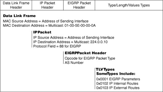
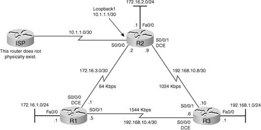
To review the EIGRP configuration commands, we will use the topology in Figure 13-3 and the addressing scheme in Table 13-3.
Notice in Figure 13-3 that the ISP router does not actually exist. For our review of default routing in EIGRP, we will use a simulated, loopback interface.
The network Command
Assuming the interfaces of all the routers are configured and activated according to the IP addresses in Table 13-3, Example 13-1 shows the EIGRP configuration using the network command.
Example 13-1 EIGRP Configuration
R1(config)#router eigrp 1
R1(config-router)#network 172.16.0.0
R1(config-router)#network 192.168.10.0
______________________________________
R2(config)#router eigrp 1
R2(config-router)#network 172.16.0.0
R2(config-router)#network 192.168.10.0
______________________________________
R3(config)#router eigrp 1
R3(config-router)#network 192.168.1.0
R3(config-router)#network 192.168.10.0
Automatic Summarization
Like RIP, EIGRP automatically summarizes networks to the classful boundary. In Example 13-2, we see that R1 and R2 are both sending the classful network 172.16.0.0/16 to R3.

R3 does not have the more specific subnet information. Because both paths are equal cost, R3 will load balance traffic to subnets for the 172.16.0.0/16 network. This will result in less than optimum routing at least half of the time. For example, to send traffic to a destination belonging to the 172.16.1.0/24 subnet, R3 will send traffic to both R1 and R2. Clearly, from the topology shown in Figure 13-3, R1 is the optimum path.
To ensure EIGRP routers are getting full subnet information, disable automatic summarization with the no auto-summary command, as shown in Example 13-3.
Now R3 will send traffic for the R1 LAN to R1 and the R2 LAN to R2. Example 13-4 shows the new routing table for R3 after automatic summarization is disabled.

Manual Summarization
With automatic summarization disabled, EIGRP no longer benefits from the smaller routing tables that can result from summarized classful network routes. To control the size of routing tables, you can use manual summarization to specify that a specific interface sends a summary route instead of the individual subnets. This also works for sending supernets.
For example, assume that R3 also has routes to the 192.168.0.0/24, 192.168.2.0/24, and 192.168.3.0/24 networks in addition to the 192.168.1.0/24 LAN. We can simulate these three routes by configuring loopbacks on R3 and then add these networks to the EIGRP configuration on R3, as shown in Example 13-5.
Example 13-5 Simulated LANs on R3
R3(config)#interface loopback 0
R3(config-if)#ip address 192.168.0.1 255.255.255.0
R3(config-if)#interface loopback 2
R3(config-if)#ip address 192.168.2.1 255.255.255.0
R3(config-if)#interface loopback 3
R3(config-if)#ip address 192.168.3.1 255.255.255.0
R3(config-if)#router eigrp 1
R3(config-router)#network 192.168.0.0
R3(config-router)#network 192.168.2.0
R3(config-router)#network 192.168.3.0
R1 and R2 will now have larger routing tables, as shown for R2 in Example 13-6.
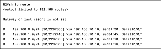
The routes in Example 13-6 can be summarized into one supernet route advertised by R3 to both R1 and R2. A supernet is a collection of contiguous classful network addresses aggregated into one route. Instead of sending four /24 routes for the classful networks 192.168.0.0, 192.168.1.0, 192.168.2.0, and 192.168.3.0, we can configure a manual summary route as 192.168.0.0/22.
Manual summary routes must be configured on the interface that you want the summary route to be sent out of. The syntax for manual summary routes with EIGRP is as follows:
Router(config-if)#ip summary-address eigrp as-number network-address subnet-mask
Because R3 has two EIGRP neighbors, the EIGRP manual summarization in configured on both Serial 0/0/0 and Serial 0/0/1, as shown in Example 13-7.
R1 and R2 now have smaller routing tables because the four networks are summarized into one route, as highlighted in Example 13-8 for R2.

EIGRP Default Route
The “quad zero” default static route can be used with any currently supported routing protocols. In our example, we configure the static default route on R2 because it is simulating a connection to ISP. Example 13-9 shows the default static route configuration on R2.
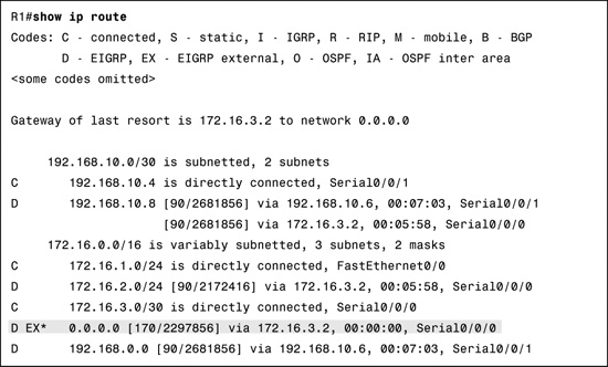
The redistribute static command tells EIGRP to include this static route in its EIGRP updates to other routers. Example 13-10 shows the routing table for R1 with the default route highlighted.
Modifying the EIGRP Metric
EIGRP uses the values bandwidth, delay, reliability, and load in its composite metric to calculate the preferred path to a network. By default, EIGRP uses only bandwidth and delay in its metric calculation, as shown in Figure 13-4.

The bandwidth metric is a static value assigned by Cisco IOS to interface types. For example, most serial interfaces are assigned the default value 1544 kbps, the bandwidth of a T1 connection. This value might or might not reflect the actual bandwidth of the interface.
Delay is the measure of time it takes for a packet to traverse a route. The delay metric is a static value based on the type of link to which the interface is connected and is measured in microseconds.
Because the bandwidth might default to a value that does not reflect the actual value, you can use the interface command bandwidth to modify the bandwidth metric:
Router(config-if)#bandwidth kilobits
In the topology shown in Figure 13-3, notice that the link between R1 and R2 has a bandwidth of 64 kbps, and the link between R2 and R3 has a bandwidth of 1024 kbps. Example 13-11 shows the configurations used on all three routers to modify the bandwidth.
Example 13-11 Modifying the Bandwidth
R1(config)#interface serial 0/0/0
R1(config-if)#bandwidth 64
____________________________________
R2(config)#interface serial 0/0/0
R2(config-if)#bandwidth 64
R2(config-if)#interface serial 0/0/1
R2(config-if)#bandwidth 1024
____________________________________
R3(config)#interface serial 0/0/1
R3(config-if)#bandwidth 1024
Modifying Hello Intervals and Hold Times
Hello intervals and hold times are configurable on a per-interface basis and do not have to match with other EIGRP routers to establish adjacencies. The syntax for the command to modify the hello interval is as follows:
Router(config-if)#ip hello-interval eigrp as-number seconds
If you change the hello interval, make sure that you also change the hold time to a value equal to or greater than the hello interval. Otherwise, neighbor adjacency will go down after the hold time expires and before the next hello interval. The command to configure a different hold time is as follows:
Router(config-if)#ip hold-time eigrp as-number seconds
The seconds value for both hello and holdtime intervals can range from 1 to 65,535. In Example 13-12, R1 and R2 are configured to use a 60-second hello interval and 180-second hold time.
Example 13-12 Modifying the Hello Intervals and Hold Times
R1(config)#interface s0/0/0
R1(config-if)#ip hello-interval eigrp 1 60
R1(config-if)#ip hold-time eigrp 1 180
__________________________________________
R2(config)#interface s0/0/0
R2(config-if)#ip hello-interval eigrp 1 60
R2(config-if)#ip hold-time eigrp 1 180
EIGRP Verification and Troubleshooting
To verify any routing configuration, you will most likely depend on the show ip route, show ip interface brief, and show ip protocols commands. The routing table should have all the expected routes. If not, check the status of the interfaces to make sure that no interfaces are down or misconfigured. Use the show ip protocols command to verify that EIGRP and that most of your EIGRP configurations are operational, as shown in Example 13-13.

For EIGRP, you can use two tables in addition to the routing table to verify and troubleshoot the configuration—the neighbor table and the topology table.
First, verify that the expected neighbors have established adjacency with the show ip eigrp neighbors command. Figure 13-5 shows the output for R2 with a brief explanation of each part.

If EIGRP is not routing as you expect, you can use the show ip eigrp topology command to view all the routes that are currently part of the EIGRP database, including routes that are installed in the routing table and potential backup routes as shown in Example 13-14 for R2.
Example 13-14 The EIGRP Topology Table
R2#show ip eigrp topology
IP-EIGRP Topology Table for AS(1)/ID(10.1.1.1)
Codes: P - Passive, A - Active, U - Update, Q - Query, R - Reply,
r - reply Status, s - sia Status
P 0.0.0.0/0, 1 successors, FD is 128256
via Rstatic (128256/0)
P 192.168.10.4/30, 1 successors, FD is 3523840
via 192.168.10.10 (3523840/2169856), Serial0/1/1
P 192.168.0.0/22, 1 successors, FD is 3014400
via 192.168.10.10 (3014400/28160), Serial0/1/1
P 192.168.10.8/30, 1 successors, FD is 3011840
via Connected, Serial0/1/1
P 172.16.1.0/24, 1 successors, FD is 3526400
via 192.168.10.10 (3526400/2172416), Serial0/1/1
via 172.16.3.1 (40514560/28160), Serial0/1/0
P 172.16.2.0/24, 1 successors, FD is 28160
via Connected, FastEthernet0/0
P 172.16.3.0/30, 1 successors, FD is 40512000
via Connected, Serial0/1/0
EIGRP-specific terms you should know so you can interpret the output in Example 13-14 include the following:
![]() Successor:: A neighboring router that is used for packet forwarding and is the least-cost route to the destination network.
Successor:: A neighboring router that is used for packet forwarding and is the least-cost route to the destination network.
![]() Feasible Distance (FD):: Lowest calculated metric to reach the destination network.
Feasible Distance (FD):: Lowest calculated metric to reach the destination network.
![]() Feasible Successor (FS):: A neighbor who has a loop-free backup path to the same network as the successor by satisfying the feasibility condition.
Feasible Successor (FS):: A neighbor who has a loop-free backup path to the same network as the successor by satisfying the feasibility condition.
![]() Feasibility Condition (FC):: The FC is met when a neighbor’s reported distance (RD) to a network is less than the local router’s FD to the same destination network.
Feasibility Condition (FC):: The FC is met when a neighbor’s reported distance (RD) to a network is less than the local router’s FD to the same destination network.
To review the concepts of successor, feasible distance, and feasible successor, let’s look at a detailed description of the highlighted entry in Example 13-13.
The first line displays the following:
![]() P:: This route is in the passive state, which means the route is stable and not actively seeking a replacement. All routes in the topology table should be in the passive state for a stable routing domain.
P:: This route is in the passive state, which means the route is stable and not actively seeking a replacement. All routes in the topology table should be in the passive state for a stable routing domain.
![]() 172.16.1.0/24:: This is the destination network that is also found in the routing table.
172.16.1.0/24:: This is the destination network that is also found in the routing table.
![]() 1 successors:: This shows the number of successors for this network. If multiple equal-cost paths exist to this network, there will be multiple successors.
1 successors:: This shows the number of successors for this network. If multiple equal-cost paths exist to this network, there will be multiple successors.
![]() FD is 3526400:: This is the FD, the EIGRP metric to reach the destination network.
FD is 3526400:: This is the FD, the EIGRP metric to reach the destination network.
The first entry shows the successor:
![]() via 192.168.10.10:: This is the next-hop address of the successor, R3. This address is shown in the routing table.
via 192.168.10.10:: This is the next-hop address of the successor, R3. This address is shown in the routing table.
![]() 3526400:: This is the FD to 172.16.1.0/24. It is the metric shown in the routing table.
3526400:: This is the FD to 172.16.1.0/24. It is the metric shown in the routing table.
![]() 2172416:: This is the RD of the successor and is R3’s cost to reach this network.
2172416:: This is the RD of the successor and is R3’s cost to reach this network.
![]() Serial0/1/1:: This is the outbound interface used to reach this network, also shown in the routing table.
Serial0/1/1:: This is the outbound interface used to reach this network, also shown in the routing table.
The second entry shows the feasible successor, R1. (If no second entry exists, there are no FSs.)
![]() via 172.16.3.1:: This is the next-hop address of the FS, R1.
via 172.16.3.1:: This is the next-hop address of the FS, R1.
![]() 40514560:: This would be R2’s new FD to 192.168.1.0/24 if R1 became the new successor.
40514560:: This would be R2’s new FD to 192.168.1.0/24 if R1 became the new successor.
![]() 28160:: This is the RD of the FS or R1’s metric to reach this network. This value, RD, must be less than the current FD of 3526400 to meet the FC.
28160:: This is the RD of the FS or R1’s metric to reach this network. This value, RD, must be less than the current FD of 3526400 to meet the FC.
![]() Serial0/1/0:: This is the outbound interface used to reach the FC, if this router becomes the successor.
Serial0/1/0:: This is the outbound interface used to reach the FC, if this router becomes the successor.
To see all the possible routes in the EIGRP topology database, including routes that do not meet the feasibility condition, use the all-links option, as shown in Example 13-15.
Example 13-15 The EIGRP Topology Table with All Links
R2#show ip eigrp topology all-links
IP-EIGRP Topology Table for AS(1)/ID(10.1.1.1)
Codes: P - Passive, A - Active, U - Update, Q - Query, R - Reply,
r - reply Status, s - sia Status
P 0.0.0.0/0, 1 successors, FD is 128256, serno 3
via Rstatic (128256/0)
P 192.168.10.4/30, 1 successors, FD is 3523840, serno 8
via 192.168.10.10 (3523840/2169856), Serial0/1/1
via 172.16.3.1 (41024000/20512000), Serial0/1/0
P 192.168.0.0/22, 1 successors, FD is 3014400, serno 9
via 192.168.10.10 (3014400/28160), Serial0/1/1
via 172.16.3.1 (41026560/20514560), Serial0/1/0
P 192.168.10.8/30, 1 successors, FD is 3011840, serno 6
via Connected, Serial0/1/1
via 172.16.3.1 (41536000/21024000), Serial0/1/0
P 172.16.1.0/24, 1 successors, FD is 3526400, serno 10
via 192.168.10.10 (3526400/2172416), Serial0/1/1
via 172.16.3.1 (40514560/28160), Serial0/1/0
P 172.16.2.0/24, 1 successors, FD is 28160, serno 1
via Connected, FastEthernet0/0
via 172.16.3.1 (41538560/21026560), Serial0/1/0
P 172.16.3.0/30, 1 successors, FD is 40512000, serno 2
By comparing the output from Example 13-14 with the output from Example 13-15, you can see that EIGRP has more routes in the routing table than shown initially. But these additional routes do not meet the feasibility condition. Therefore, DUAL must first query neighbors to make sure there is not a better route out there before installing a route that does not meet the feasibility condition. This is the essence of how DUAL avoids loops.
DUAL’s finite state machine—how the algorithm comes to a final decision—is graphically represented in the flow chart in Figure 13-6.

To monitor DUAL’s FSM in action, use the debug eigrp fsm command. Then shut down an interface on the router to see how DUAL reacts to the change in the topology.