CHAPTER 13
INTRODUCTION TO MODELING WITH MILKSHAPE
In this and the following chapters, we will be delving into the world of low-poly modeling. We’ll talk about techniques and methods that can be applied to other tools, such as the expensive 3D Max or Maya, but the practical focus will be geared toward using MilkShape, UVMapper, and other low-cost tools that are included on the companion DVD. Internet URLs can be found in Appendix B.
MILKSHAPE 3D
In Chapter 9 we created a skin for a simple soup can—remember that? Well, in this chapter we’re going to create the model and skin it with the texture you created earlier, only this time we will go beyond just the simple soup can. But first, let’s start at the beginning and learn a bit about MilkShape.
MilkShape 3D is a great low-cost low-poly 3D modeling tool created by a fellow named Mete Ciragan. Like most successful shareware applications it has evolved over the years, as Mete added features requested by his user community. He also added the capability for users to create their own plug-ins to provide additional features and import-export filters.
MilkShape is not as complex as the more expensive tools, but that does not in any way imply that it is not a capable program, especially in the low-poly world that computer games inhabit. In fact, the stripped-down nature of MilkShape certainly makes it easier to learn than most of the “big boys.”
Installing MilkShape 3D
If you want to install only MilkShape 3D, do the following:
1. Browse to your DVD in the 3D3ETOOLSMILKSHAPE 3D directory. (By the way, MS3D is the abbreviated form for MilkShape 3D. You might encounter it from time to time.)
2. Locate the ms3d185beta1.zip file, and double-click it to unzip it. The setup program should automatically run.
3. Click the Next button for the Welcome screen.
4. Follow the various screens, and take the default options for each one, unless you know you have a specific reason to do otherwise.
5. Close MilkShape.
6. There’s a new version of the DTS Exporter Plus plug-in that we’ll use for getting our models into Torque, so let’s install it: in the 3D3EToolsMilkshape 3DMS2DTSEXPORTERPLUS folder, locate a zip file, ms2dtsExporterPlus.zip, which contains the DTS Exporter Plus plug-in.
7. Open the zip file and drag ms2dtsExporterPlus.dll into your MilkShape 3D installation directory.
The MilkShape 3D GUI
If you look at Figure 13.1, you can readily see that the MilkShape working environment, or window, is divided into three areas: the menu, the views, and the toolbox.
Tip
If you only have three views in your window when you first run MilkShape, choose Window, Viewports, 4 Window, and you should get something close to what you see in Figure 13.1.
In Figure 13.1 there are four places where the model can be seen. Each of these is what MilkShape calls a window. We will call them frames in this book, because as you probably already know, MilkShape itself is in a window.
A view is the angle or direction at which you look at an object. For example, if you stand in front of an object and look at it, you are seeing the Front view. From above, it is the Top view.
A viewport is the little frame inside the MilkShape window in which a view of a model is presented.
Thus in Figure 13.1 the 3D view is in the 3D viewport, located in the lower-right frame in the MilkShape window.
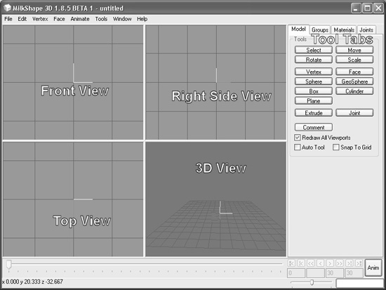
You’ll notice in Figure 13.1 that I’ve labeled the different views. This is the way you should use your views for models that you create for Torque. Other applications and games may require your models to be oriented differently.
Three of the views are wire-frame–only views; they enable you to look at your model from directly above, directly in front, and the right-hand side. The fourth view is a 3D view in which you can rotate your model various different ways and view it as a wire-frame, shaded, or fully textured model with lighting cues.
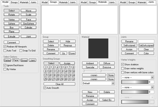
Figure 13.2 shows the tools available in the toolbox section. Although some tools for different operations are only available in the menus, most of the time you will be working with the tools in the toolbox.
Navigating in Views
In the wire-frame views, you can move the view around by holding down the Ctrl key and clicking and dragging in the window.
If you hold down the Shift key and drag the mouse while in Move mode, (click Move on the Model tab) you can zoom in or out. Be careful though—if you are in Select mode (from the Model tab), then drag-move won’t work. With practice you can master this drag-move and it will become quite useful. In all other modes the shift-drag action will always zoom the view in or out with no alternation.
Figure 13.2
The toolbox contents.
If you have a wheel mouse, then the wheel can be used to zoom in or out. You will have to click in the view to get focus into the view before the zoom will work.
The 3D view allows the view movement in the same ways as the other views, except the wheel mouse zoom works backward.
View Scale and Orientation
When you are viewing an object from the front in MilkShape, the Y-axis is positive going up, the X-axis is positive going to the right, and the Z-axis is positive going to the front. This makes it a right-handed coordinate system.
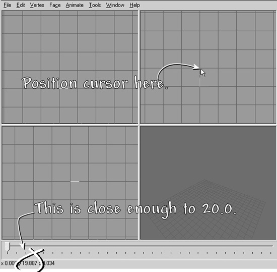
If you look at the Right Side view (the view at the upper right of the four), you will see in the center the axis “bugs” for the Y- and Z-axes. Although it is not visible in the black-and-white pictures in this book, the Y-axis line is cyan, and the Z-axis line is magenta. The place where these two lines meet is the (0,0,0) coordinate in object space. Hold your mouse cursor over the first grid line above the (0,0,0) location, and look down to the lower-left corner of the MilkShape window while keeping your cursor over that grid line. You should see the Y-axis value at about 20.0 or so (see Figure 13.3). If you see something like 20.005 or 19.885, that’s good enough. If you don’t see 20.0 or so, zoom the view in or out until you do. The length of any of the axis lines should be half of a grid square tall.
Figure 13.3
Checking the zoom in the Right Side view.
Note
When you’re scrolling in or out, adjusting the scale size, you will notice the spacing of the grid lines change. In fact you may even see them pop to extra large or extra small suddenly. Don’t panic, this is just software accommodating how far in or how far out you zoomed. The key factor is the number at the lower left of the MilkShape window.
Adjust your other two wire-frame views to the same scale. If you position your cursor one grid line directly above the (0,0,0) point on the Front view (upper left), you should see the 20.0 or so also for the Y value, but for the Top view, the same relative positioning will be affected in the Z-axis.
Figure 13.4 contains various notations to help you understand the coordinate display system. In this figure I’ve left in MilkShape’s viewport labels above each viewport’s frame in order to illustrate the variation that emerges with the Torque Right Side view being seen in MilkShape’s Left viewport.
Figure 13.4
Torque-oriented object in the MilkShape viewports.
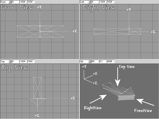
The whole point of this little exercise is to expose you to the coordinate display and to ensure that your layout matches the one we’ll be working with here. Of course, at times when you zoom in and out this might change, but now you have a method of recalibrating when necessary.
The Soup Can Revisited
Now that you have a bit of a grasp of what you are looking at in the GUI and how to move your views around to look at your model, we’ll move on to actually creating a quick model to get your feet wet. There’s nothing like doing for learning!
Creating the Basic Shape
A closed can is a cylinder. A cylinder is what we call a primitive shape, like a sphere or a cube. The primitives are added together in various ways to build up more complex shapes.
1. Choose the Model tab in the toolbox.
2. Click Cylinder.
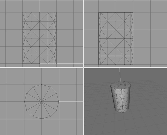
3. Position your cursor in the Right Side view about three grid lines above (0,0,0) and one grid line to the left. Click and drag down and to the right until your object is similar to Figure 13.5. You’ll have to right-click in the 3D view and choose Wireframe Overlay to match the picture below.
4. Choose the Groups tab. You will see a single group named Cylinder01 (it may be a higher number if you made other cylinders and deleted them—MilkShape just adds 1 to the number at the end during its auto-naming).
Tip
You may recall encountering the term mesh way back in Chapter 3. In MilkShape, the word group is actually an analog for the word mesh. They mean essentially the same thing.
5. Click the group name to highlight it, if it isn’t already, and then type can in the box to the right of the Rename button where it says “Cylinder01”.
6. Click Rename, and the group will now be called “can”.
7. Choose the Materials tab.
8. Click New.
9. Type label into the Materials Rename box.
10. Click Rename.
11. In the Material frame of the Materials tab you will see two buttons labeled “<none>”. These are the texture buttons. The top one assigns the standard texture, and the bottom one enables you to assign a texture whose alpha channel you want to use for this material.
12. Click the top texture button. You will get a file dialog box.
13. Browse your way to 3D3ERESOURCESCH9, and double-click the can.jpg file.
14. Now choose the Groups tab again, and make sure your cylinder’s group is selected in the list. If your can is not already highlighted in red, click Select. You will see your can highlighted in red in the three wire-frame views.
15. While your can is still selected, switch back to the Materials tab, choose your new material in the list, and click Assign.
Tip
If your screen resolution is set to 800 × 600 or less, you will not be able to see the entire Assign or Select By buttons. The top one-quarter or so of those buttons is just visible on the lower-right corner. Assign is located below the Rename button, and Select By is located below the edit box that is to the right of the Rename button.
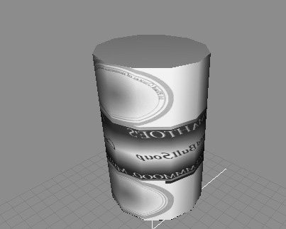
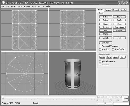
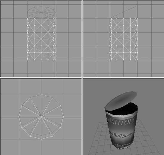
16. Right-click in the 3D view, and ensure Wireframe Overlay is deselected. Your can should appear with the texture wrapped around it, like in Figure 13.6.
17. Save your work so far as mynewcan.ms3d somewhere, by choosing File, Save As. 3D3ERESOURCESCH9 is a good place to save this file.
18. In preparation for UV unwrapping the can object, choose File, Export, Wave-front OBJ, and export the file to 3D3ERESOURCESCH9mynewcan.obj.
Okay, so we have the soup can made, and we’ve assigned the texture to it. The reason the texture doesn’t fit right yet is because the texture coordinates haven’t been mapped to the object yet. That’s our next step.
UV Unwrapping the Can
In Chapter 9 we encountered some of the theory and process behind UV unwrapping and mapping. In a later section in this chapter we’ll go into more theory, as well as more detail about the UVMapper tool. For our purposes at the moment, we just want to get the texture skin mapped correctly onto the can.
Whether the skins are created before the object or the object is created first will probably change from project to project or even from phase to phase within a project. At this point in the book, we already have a skin—can.jpg—so we want to make sure the can will unwrap to match the skin. This isn’t a problem in this case. It may be a problem with other projects though, so be aware of that possibility.
1. Using Windows Explorer, browse your way to 3D3ETOOLSUVMAPPER, then locate and launch UVMapper.exe.
2. Maximize the window when it opens.
3. Find the file you exported, 3D3ERESOURCESCH9mynewcan.obj, and load it: Select File, Load.
4. You will see a dialog listing some statistics about the object. Click OK.
5. You will see a bunch of triangles fill your window. Ignore them for the moment.
6. Choose Edit, New UV Map, Cylindrical Cap. You will get a Cylindrical Cap Mapping dialog box.
7. Click OK. You will then get a layout of the can’s triangles (like that in Figure 13.7), with a rectangular block of triangles across the middle and a circle of triangles at both top and bottom.
8. Choose File, Save Model. The OBJ Export Options dialog box then appears.
9. Set the options boxes as shown in Table 13.1, and click OK.
10. Replace the OBJ file 3D3ERESOURCESCH9mynewcan.obj by saving over it.
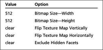
11. Choose File, Save Texture Map. The BMP Export Options dialog box appears.
12. Set the options to the values shown in Table 13.2 and then click OK.
13. Save to the file name 3D3ERESOURCESCH9mynewcan.bmp. This is the texture map, or UV mapping template, for your can.
Figure 13.7
Unwrapping the can in UVMapper.
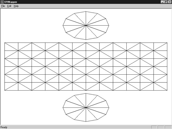
Table 13.1 UVMapper OBJ Export Options Values
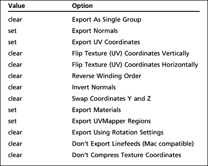
Table 13.2 UVMapper BMP Export Options Values
14. Switch back to MilkShape.
15. Ensure that the can group is selected by choosing the Groups tab, and clicking on the can group in the list, then clicking the Select button. The selection should be red.
16. Click the Delete button. You will replace this object with the one you exported from UVMapper.
17. Choose File, Import, Wavefront Obj, and import the mynewcan.obj file you saved from UVMapper.
18. On the Groups tab, click on your new object (mynewcan.obj), then in the Group area, click the Select button. You can also rename it if you like.
19. With the new object selected, choose the Materials tab.
Caution
After importing the .obj file from UVMapper into MilkShape, you might discover another copy of the material in the Materials list. If so, delete the second entry. This appears to be a minor bug in UVMapper. The second copy of the material doesn’t have any textures assigned to it. If you only have one material, and it has the proper texture assigned to it, then leave it alone.
20. Choose the label material, and then click Assign.
21. Your texture should appear on the can in the 3D view, wrapped correctly.
22. If no texture appears, click in the 3D window to force an update.
23. If there is still no texture, make sure that you have the 3D window still set to Textured, by right-clicking in the 3D window and checking the menu. Save your work now.
Enhancing the Soup Can Model
Have a seat and stew on that for a while. When you are done, we’ll carry on and start hammering at the soup can and improve the model.
How about we open the can up? The can model has a top and a bottom. We want to leave the bottom where it is and flip the top lid up.
First we need to separate the lid from the can.
1. Choose the Model tab, and click Select in the Tools area.
2. In the Select Options area, click Vertex, and select all the vertices at the bottom of the can, as shown in Figure 13.8. Use either the Side view or the Front view, and make sure that Ignore Backfaces is not checked.
3. From the menu bar, choose Edit, Hide Selection. The dots of the vertices will disappear. This means that none of the vertices for the bottom face are selectable.
4. Now in the Model tab, in the Select Options area, click Face. Make sure that By Vertex is checked.
Figure 13.8
Selecting the bottom vertices.
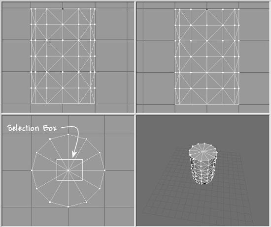
5. In the Top view, select the vertex in the center of the can, as in Figure 13.9. Because you had hidden the bottom vertices, only the single center vertex for the top of the can has been selected. And because you are actually selecting faces by vertex, then all the top lid faces—and only those faces—have been selected.
Figure 13.9
Selecting the center vertex.
6. In the Groups tab, click Regroup. This will create a new mesh with only the faces from the top of the can. The mesh will be named “Regroup01”. Rename this mesh to “lid” in the same manner that you did earlier when you renamed the cylinder mesh to “can”.
7. Switch back to the Model tab. Your lid mesh should still be selected.
8. Click the Move button, and then click and drag in the Side view to move the lid up and to one side from the rest of the can.
9. Click the Rotate button, and then click and drag in the Side view to rotate the lid as if you were bending the lid back (see Figure 13.10).
10. If necessary, repeat step 8 to position the lid properly. You might have to adjust it in one of the other views, depending on how you initially moved the lid.
Figure 13.10
The can with lid opened.
11. Choose the Groups tab, and click Regroup. The lid faces will now be part of their own group.
12. Choose Edit, Duplicate Selection. Another copy of the lid will be made in exactly the same location as the original.
13. From the menu bar, choose Face, Reverse Vertex Order. This will invert the normals of the lid’s faces, making it viewable from the other direction. You will recall that the normal of a face is, in the simplest terms, the direction that a face is facing.
14. On the Groups tab, add the original lid to your selection by clicking on the first lid group and then clicking the Select button in the group area.
15. Select Vertex, Weld Together. The original lid is viewable from one side, and the copy is viewable from the other. They now share the exact same vertices.
If you rotate your can in the 3D view, you’ll see that your lid now has the lid part of the skin on both sides. You’ll also notice that the inside of the can is black. This is because no faces are normalized to the interior, just as the lid at first did not have any faces normalized on the side.
Tip
You may be wondering why you didn’t have to assign a material to the new faces you created with the Duplicate command. What happened is that when you grouped the original faces and the new faces together, the material that was assigned to the original lid faces was automatically assigned to the new group.
16. Repeat the preceding steps, but this time create, for the can body, a set of faces that are normalized to the interior instead of the exterior, and then group them together. You can use your UV mapping and Gimp skills to create a more realistic metallic interior to the can, instead of just repeating the exterior skin on the inside.
17. Save your work—you never know when a nice can of soup may be needed for dipping your towel in!
So, here we are. You’ve made a model of an object, using a couple of shape primitives. And you’ve learned how to make double-sided textures, rotate and move meshes (or groups), and assign skins. Feel free to explore your new capabilities. Poke around and try out the other primitives.
Menus
MilkShape can perform many more features and operations than what we’ve just gone over. In later chapters you’ll learn how to make more difficult and challenging shapes, like player-characters, vehicles, and weapons. In this chapter we’ll take a look at the program itself in more detail.
Most but not all the menus have shortcuts assigned to the keys. Typically, the ones that are used the most do have shortcuts. If you want to add your own shortcut, you can use a plug-in to do that. We’ll cover that when we discuss the Tools menu.
File
As in most Windows programs, operations in the File menu (see Figure 13.11) relate either to the creation and saving of files or to making global alterations to the current file’s properties or contents. See Table 13.3 for more detail.
Edit
The MilkShape Edit menu (see Figure 13.12) contains commands that assist the user when modifying models. It does not have Cut, Copy, or Paste but does offer commands in a similar vein for duplicating, hiding, and selecting objects. See Table 13.4 for more detail.
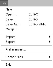
Table 13.3 MilkShape File Menu
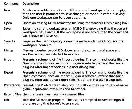
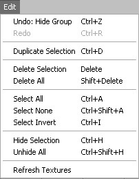
Table 13.4 MilkShape Edit Menu

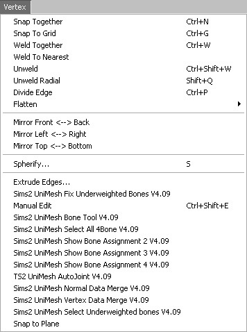
Vertex
You can perform a number of operations on vertices in a model. They are available through the Vertex menu (see Figure 13.13). In most cases you will need to ensure that you’ve selected only vertices in a model or at least have the selection mode set to Vertex. See Table 13.5 for more detail.
Face
The Face menu (see Figure 13.14) provides commands for manipulating triangles and faces in the workspace. See Table 13.6 for more detail.
Animate
The Animate menu (see Figure 13.15) is used to manipulate animation frames in the model via the Keyframer. See Table 13.7 for more detail.
Tools
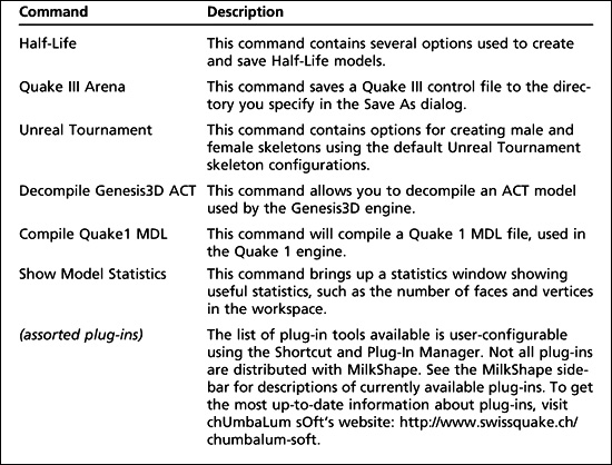
The Tools menu (see Figure 13.16) provides access to both built-in tools and user plug-in tools. The functions available are not the same as those available in the tool-box. This is a potential source of confusion. See Table 13.8 for more detail about the Tools menu.
Table 13.5 MilkShape Vertex Menu
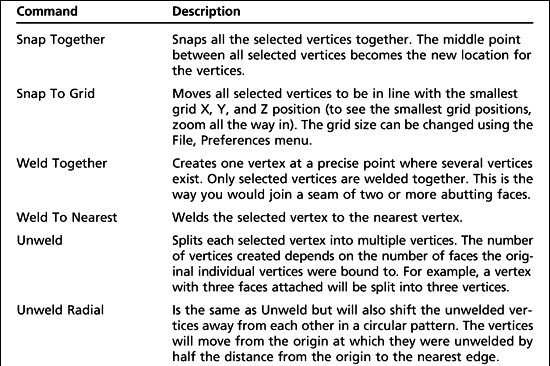
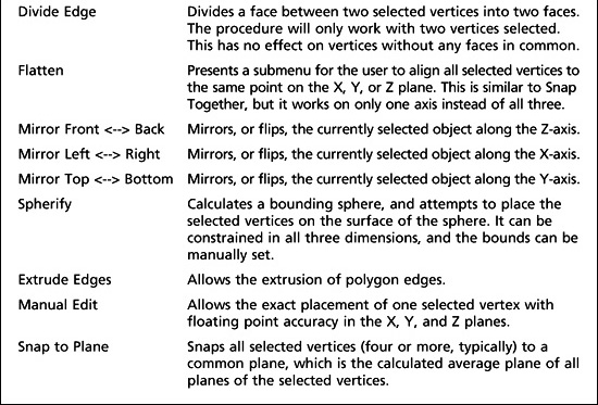
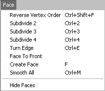
Table 13.6 MilkShape Face Menu
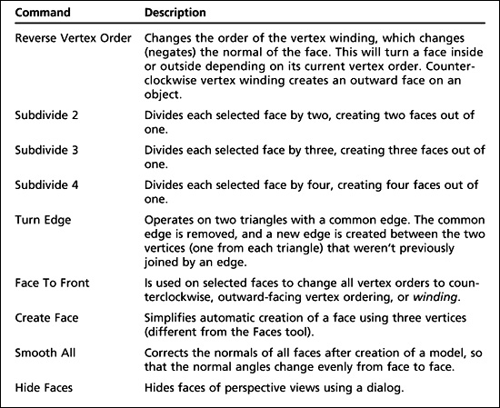
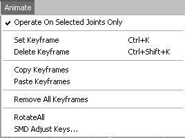
Table 13.7 MilkShape Animate Menu
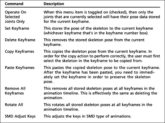
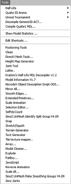
Table 13.8 MilkShape Tools Menu
MilkShape Plug-Ins
There is quite a large list of MilkShape plug-ins that extend MilkShape’s capabilities. For information about where to find them to download, tutorials about how to use them, and the names of the individual creators, see Appendix C, “Shareware and Freeware Tools.” The plug-ins that were known at the time of this writing are listed; some plug-ins are import or export filters for different file formats and aren’t included here, except for the Torque DTSPlus Exporter, because we use it in this book (the standard Torque Game Engine DTS Exporter, and the Wavefront OBJ Importer and Exporter are built into MilkShape).
![]() ms2dtsExporter. This plug-in exports models, animations, and materials to DTS model format for use with the Torque Engine. This plug-in appears in the File, Export menu.
ms2dtsExporter. This plug-in exports models, animations, and materials to DTS model format for use with the Torque Engine. This plug-in appears in the File, Export menu.
![]() ms2DTSExporterPlus. This is an advanced plug-in for exporting models, animations, and materials to DTS model format for use with the Torque Engine. This plug-in appears in the File, Export menu. It supports sequence file exporting, texture animations, trigger frames, and more.
ms2DTSExporterPlus. This is an advanced plug-in for exporting models, animations, and materials to DTS model format for use with the Torque Engine. This plug-in appears in the File, Export menu. It supports sequence file exporting, texture animations, trigger frames, and more.
![]() msSelectionEditor. This plug-in edits the selection from a 3D view. There are a lot of options, and you can read some detailed information about it here.
msSelectionEditor. This plug-in edits the selection from a 3D view. There are a lot of options, and you can read some detailed information about it here.
![]() msTimer. This plug-in lets you time how long you’ve been working on a certain model.
msTimer. This plug-in lets you time how long you’ve been working on a certain model.
![]() msEdgeExtrude. This plug-in lets you extrude edges in addition to faces.
msEdgeExtrude. This plug-in lets you extrude edges in addition to faces.
![]() msJointTool. This plug-in allows you to add joints in the middle of the hierarchy, unlink a joint from a hierarchy, and assign vertices to the closest joint (some kind of “Assign Mesh to Skeleton” tool).
msJointTool. This plug-in allows you to add joints in the middle of the hierarchy, unlink a joint from a hierarchy, and assign vertices to the closest joint (some kind of “Assign Mesh to Skeleton” tool).
![]() msSnap. This plug-in snaps not only to 1.0, but it also snaps joints.
msSnap. This plug-in snaps not only to 1.0, but it also snaps joints.
![]() msToolArray. This plug-in duplicates objects and then places the duplicates in 3D space according to user specifications.
msToolArray. This plug-in duplicates objects and then places the duplicates in 3D space according to user specifications.
![]() msVertexPlane. This plug-in is similar to the Vertex, Flatten command, except that it snaps selected vertices to a plane instead of a single point.
msVertexPlane. This plug-in is similar to the Vertex, Flatten command, except that it snaps selected vertices to a plane instead of a single point.
![]() msToolFatBoy. This plug-in will make your model fatter or thinner. This is useful for tweaking player and monster characters.
msToolFatBoy. This plug-in will make your model fatter or thinner. This is useful for tweaking player and monster characters.
![]() msOperationMirrorAll. This plug-in will mirror everything about your model over the selected plane: bones, mesh, animation—everything.
msOperationMirrorAll. This plug-in will mirror everything about your model over the selected plane: bones, mesh, animation—everything.
![]() msToolReverseAnimation. This plug-in will reverse the order of the keyframes in whatever animation you have loaded.
msToolReverseAnimation. This plug-in will reverse the order of the keyframes in whatever animation you have loaded.
![]() msToolScaleAll. This plug-in applies scale to all objects in the workspace at once.
msToolScaleAll. This plug-in applies scale to all objects in the workspace at once.
![]() msSelPolyCount. This plug-in shows the selected polygon, vertex, and unique vertex counts, as well as how many polygons there are per group.
msSelPolyCount. This plug-in shows the selected polygon, vertex, and unique vertex counts, as well as how many polygons there are per group.
![]() msBridge. This plug-in creates a mesh connecting to previously independent meshes or groups.
msBridge. This plug-in creates a mesh connecting to previously independent meshes or groups.
![]() msTerGen. This plug-in can generate random terrains or import a bitmap file to use as a height map.
msTerGen. This plug-in can generate random terrains or import a bitmap file to use as a height map.
![]() msTextGen. This plug-in generates 3D objects in the form of text.
msTextGen. This plug-in generates 3D objects in the form of text.
![]() msModelInfo. This plug-in provides more detailed information about a model than the Show Model Statistics command.
msModelInfo. This plug-in provides more detailed information about a model than the Show Model Statistics command.
![]() msTIleTextureMapper. This plug-in generates texture coordinates to geometry for tile textures (also known as seamless textures).
msTIleTextureMapper. This plug-in generates texture coordinates to geometry for tile textures (also known as seamless textures).
![]() msLathe. This plug-in takes flat geometry and turns it around the X-axis to build a 3D model.
msLathe. This plug-in takes flat geometry and turns it around the X-axis to build a 3D model.
You can install plug-ins by simply copying them to the MilkShape directory and then launching MilkShape. They will then appear under the Tools menu beneath Show Model Statistics.
Window
The Window menu (see Figure 13.17) provides commands that determine what information is available in the MilkShape window and how it is displayed. See Table 13.9 for more detail.
The Toolbox
Way back near the start of this chapter, in Figure 13.2, is a depiction of the contents of the various tabs in the toolbox. In this section here we will dig deeper into the capabilities in those tabs. Table 13.10 provides a brief summary of each toolbox tab’s functions.
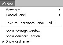
Table 13.9 MilkShape Window Menu

Table 13.10 MilkShape Toolbox Summary

You should understand that, in general, when using the functions in the toolbox, we will first have to select some object via one of the views and then operate on it using one of the toolbox commands. This sort of noun-verb operation mode requires us to make sure we have the appropriate objects selected before every action we take.
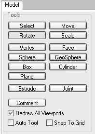
The Model Tab
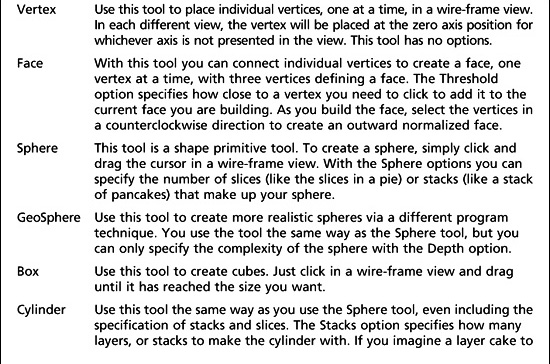
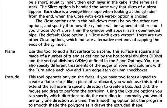
The Model tab (see Figure 13.18) contains the tools necessary to create and modify the basic shape primitives: vertices, faces, cylinders, spheres, and cubes (boxes, as MilkShape calls them). Table 13.11 shows the functions of the Model tab’s buttons.
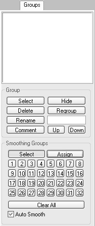
The Groups Tab
You will often want, or need, to organize your model faces into groupings that make either visual or logical sense. Whether you organize them as meshes that make visual sense or simply as logical groups, you do this with the Groups tab, shown in Figure 13.19. The Torque DTS Exporter uses special groups with the name collision to define collision meshes. Table 13.12 presents the functions available from the Groups tab.
The Materials Tab
With the Materials tab (see Figure 13.20), you can define the textures that will be used to skin your model, as well as what characteristics they will have when displayed. Special materials are also used to define certain model characteristics to the Torque DTS Exporter. Table 13.13 explains the functions of the Materials tab.
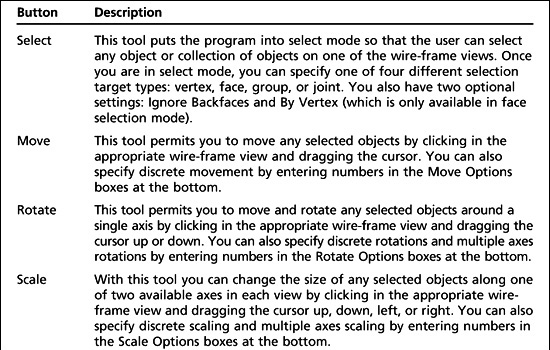
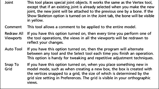
Table 13.11 Model Tab Functionality
The Joints Tab
With the Joints tab (see Figure 13.21), you can specify the joints for skeletons, which are used in animations. Joints are also used as substitutes for the concepts of special nodes that are used by the Torque DTS Exporter. Table 13.14 describes the Joints tab functions.
The Keyframer
The Keyframer (see Figure 13.22) is a special tool used for defining animations for your model. With it, you can save skeletal positions in a model. You then produce animation by storing several keyframes to the Keyframer and playing them back. There is a set of controls for managing the playback. Typically, only frames where changes take place need to be set by the user—hence the term keyframe. Keyframes are key to the animation. MilkShape 3D will fill in the pose or position frames between the keyframes. You must click the Anim button at the lower right in order to work with the Keyframer.
Table 13.12 Groups Tab Functionality
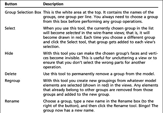
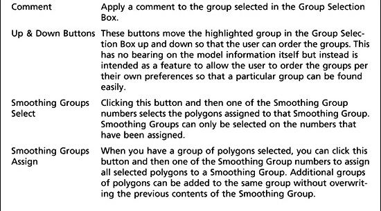
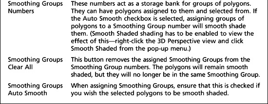
Figure 13.20
The Materials tab.
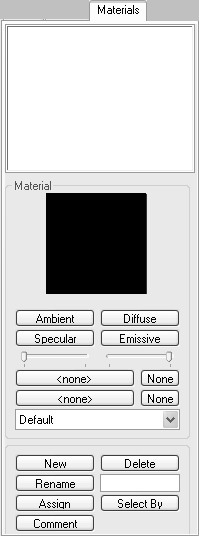
Table 13.13 Materials Tab Functionality
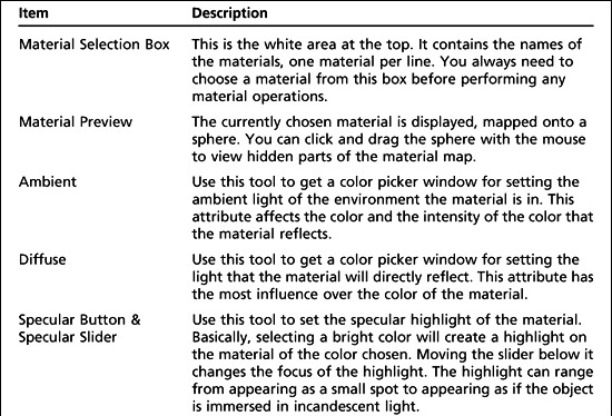
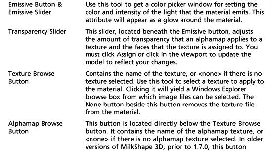
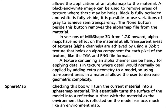
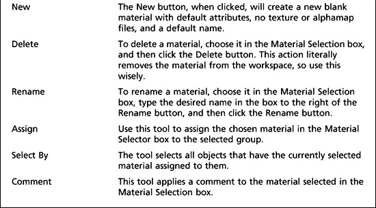
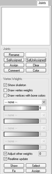
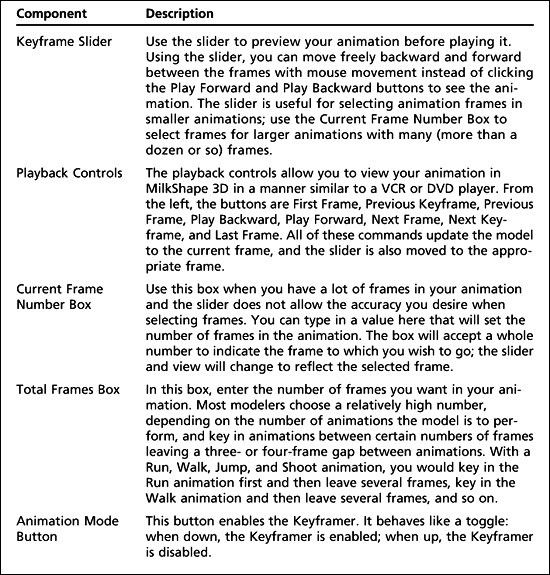
Table 13.15 describes the primary Keyframer functions.
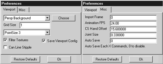
The Preferences Dialog Box
The Preferences dialog box (see Figure 13.23), which you reach by choosing File, Preferences, has two tabs. The Viewport tab is used to the set up the viewport’s attributes, and the Misc tab offers miscellaneous settings. Table 13.16 provides details about each setting in the two tabs.
Table 13.14 Joints Tab Functionality
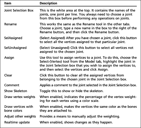
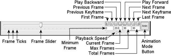
Table 13.15 Keyframer Functionality
Other Features
MilkShape has a few other features that we won’t cover in great depth, but two that deserve at least an honorable mention are the Texture Coordinate Editor and the Message Panel.
Figure 13.23
The Preferences dialog box.
The Texture Coordinate Editor provides primitive texture-mapping capability. It has some rather severe limitations that prevent it from being used in even moderately complex models. The biggest limitation is that it doesn’t unwrap meshes independently. For this reason we use external tools, like UVMapper. UVMapper may be a bit more awkward to use, because it isn’t integrated, but it does a better job, providing more flexibility and control.
The Message Panel displays output from executing plug-ins and modeling operations. It can be useful for providing insight into how MilkShape does its work, but its downfall is the screen space it takes up.
UVMAPPER
Earlier in this chapter—and even earlier than that, in Chapter 9—we used the UVMapper program created by Steve Cox to help us skin a model. As promised, here is the section with the detailed information on UVMapper. We won’t cover every detail. Instead, we will concentrate on those details that we can apply to our own needs here in this book.
The first thing to know about UVMapper is that it only operates on models saved in OBJ format, as created by the Alias Wavefront program. The UV unwrapping principles involved are the same for all similar tools. The author of UVMapper has also created UVMapper Pro, a newer release with many more features and greater flexibility. The companion DVD includes a demo of UVMapper Pro, a restricted version (you can’t save output, which, of course, we need to do). If you want to check out the enhanced features later, go ahead and poke around.
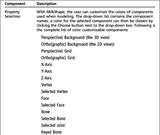
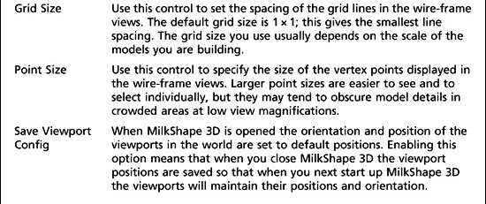
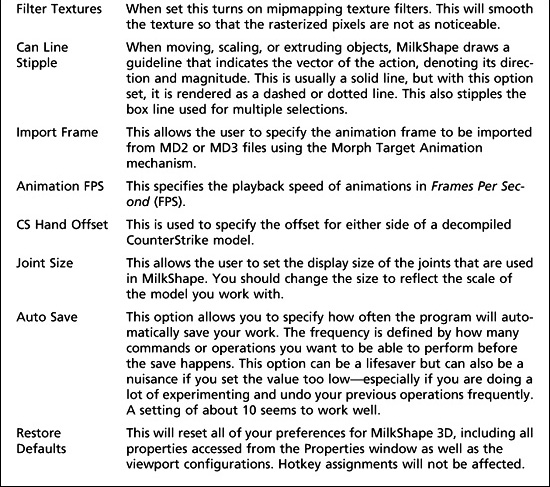
Table 13.16 Preferences Choices
The File Menu
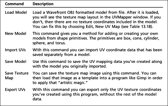
As is true in most programs, UVMapper’s File menu provides commands for loading, saving, importing, and exporting files. See Table 13.17 for descriptions.
The Edit Menu
The Edit menu is where the real power of UVMapper resides. Table 13.18 provides more information.
Table 13.17 UVMapper File Menu
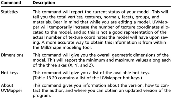
The Help Menu
The Help menu provides the user some assistance when working with the program. Table 13.19 provides more detail, and Table 13.20 provides a list of UVMapper hot keys.
UV Mapping
When you choose Edit, New UV Map you will be presented with a choice of five different unwrapping methods:
![]() Planar
Planar
![]() Box
Box
![]() Cylindrical
Cylindrical
![]() Cylindrical Cap
Cylindrical Cap
![]() Spherical
Spherical
Table 13.18 UVMapper Edit Menu
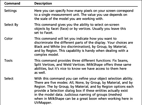
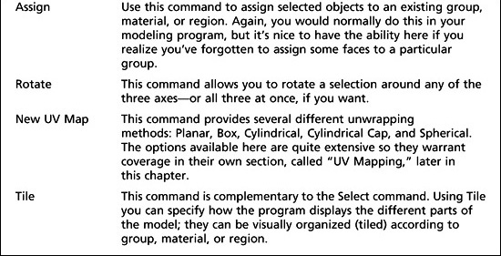
Table 13.19 UVMapper Help Menu
Each of these methods is described in more detail here. Sometimes, even when you know exactly what the unwrapping method is supposed to do, you will be surprised at the results, so don’t be afraid to experiment. Once you’ve loaded a model, you can keep trying the different unwrapping methods with different settings. Each time you do it, the program begins from scratch, so you don’t have to worry about undoing your previous efforts.
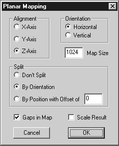
Planar
When you use the Planar method, you will be presented with the dialog box depicted in Figure 13.24. Table 13.21 provides details about using the Planar method.
Box
When you use the Box method, you will be presented with the dialog box depicted in Figure 13.25. You can get more information on using the Box method in Table 13.22.
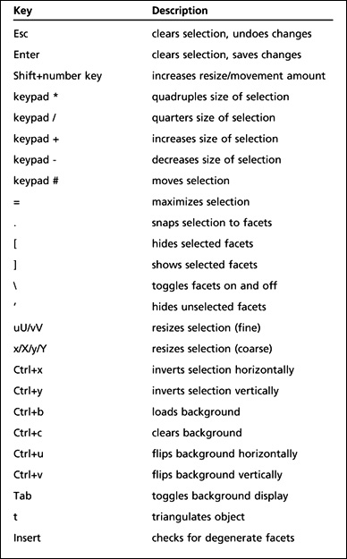
Figure 13.24
The Planar Mapping dialog box.
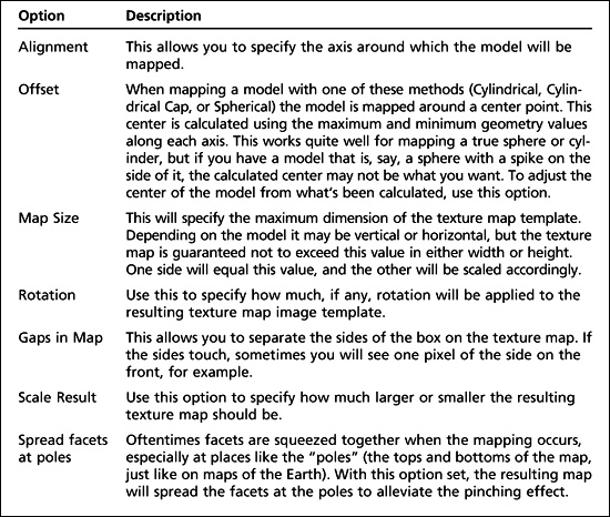
Cylindrical
When you use the Cylindrical method, you will be presented with the dialog box depicted in Figure 13.26. Table 13.23 provides details about using the Cylindrical method.
Cylindrical Cap
When you use the Cylindrical Cap method, you will be presented with the dialog box depicted in Figure 13.27. Table 13.24 provides details about using the Cylindrical Cap method. This method is similar to the Cylindrical method, except that it assumes you are unwrapping a cylinder with end caps, as if there were closed lids on both ends of a can. The caps are mapped separately from the tubing of the cylinder.
Spherical
When you use the Spherical method, you will be presented with the dialog box depicted in Figure 13.28. You can get more information on using the Spherical method in Table 13.25.
Table 13.21 Planar Mapping Options

Figure 13.25
The Box Mapping dialog box.
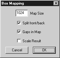
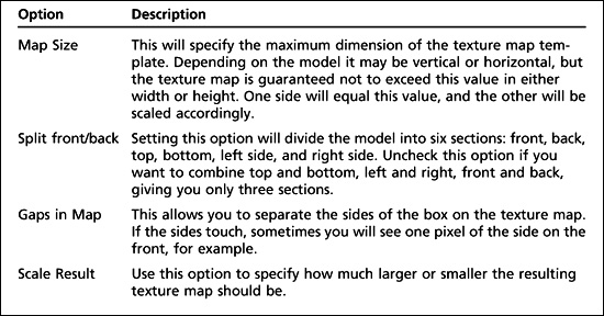
Table 13.22 Box Mapping Options
MOVING RIGHT ALONG
Well, there you have two pretty comprehensive, low-cost modeling tools: MilkShape 3D by Mete Ciragan and UVMapper by Steve Cox. These guys have done an admirable job creating these programs in the shareware or freeware spirit. Not only do they deserve a round of applause and a big thank-you, but you could also perhaps send a few dollars their way by registering their shareware programs. The cost is minuscule, and the benefits are great.
Figure 13.26
The Cylindrical Mapping dialog box.
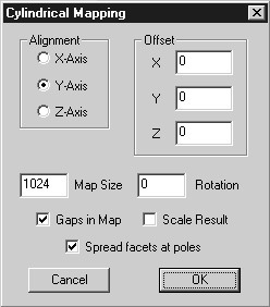
Table 13.23 Cylindrical Mapping Options
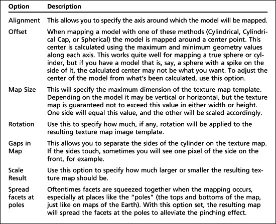
Figure 13.27
The Cylindrical Cap Mapping dialog box.
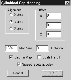
Table 13.24 Cylindrical Cap Mapping Options
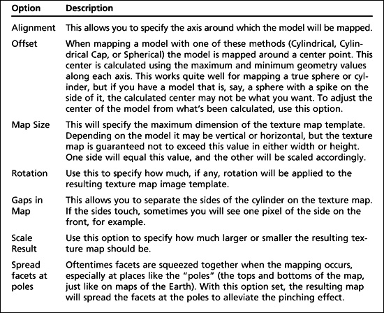
Figure 13.28
The Spherical Mapping dialog box.

Table 13.25 Spherical Mapping Options
By using the common Wavefront file format, we can use each tool in complementary ways to create models for our games. This is a pretty common theme; notice also that we’ve used Gimp—another low-cost tool (in fact, free!)—in the same way in conjunction with MilkShape. In the next few chapters we will tackle the Big Jobs: animated characters, vehicles, and weapons. It would not be wasted effort if you wanted to take some time out at this point to practice by designing and building some models to your own specifications.
The more you use a tool, make mistakes, and figure out what you did wrong and then make any necessary corrections on your own, the more proficient you will become.