
5.4 Video Plus Depth Coding
We have reviewed many different approaches to compress stereo video sequences. We notice that the main principles of all the discussed approaches so far only take the information directly from the pixels captured by stereo cameras and try to utilize the existing video coding framework to deliver the video with the highest possible fidelity. Potentially, the video coding performance can be further improved during the stereo video codec design phase by addressing both the geometric location of the camera arrays and the 3D scene to video camera. One potential solution is through the depth-image-based rendering (DIBR) approach [19, 20].
The inputs of the DIBR process consist of one color image frame, which represents the color information, and one depth map, which represents the depth information for each corresponding pixel in the image. The 3D coordinate for each pixel from the input image frame can be calculated with the aid of the depth information. Then, the DIBR process sets up two virtual cameras in a parallel configuration, which represent left view and right view, and projects those pixels in the 3D coordinate back to each virtual 2D image plane belonging to each virtual camera.
Figure 5.13 illustrates the details of the DIBR process. Let CC represent the viewpoint of the original captured camera, CL the viewpoint of the virtual left camera, and CR the viewpoint of the virtual right camera. Denote f as the focal length of the camera CC, and d as the distance from each virtual camera to the central camera. For each pixel XC with location (xc, y) in CC camera coordinate, we have its corresponding depth information z(xc, y) and can construct its 3D position as p(xc, y), as shown in the figure. The horizontal distance between p and CC is |xc|·z (xc, y)/f and the horizontal distance between p and CL is d + xc·z(xc, y)/f. The projection of pixel p on the left virtual camera image plane has the coordinate (xl, y), where
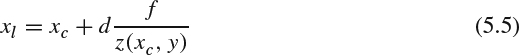
Similarly, the projection of pixel p on the right virtual camera image plane has coordinate (xr, y), where
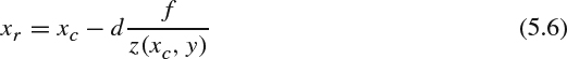
Figure 5.13 Illustration of DIBR.
The rendering process will take place for all pixels to generate the required two views. With a fixed camera configuration d and f, the DIBR rendering process will simply be a horizontal offset and can be implemented via a lookup table approach regarding to the depth.
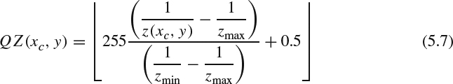
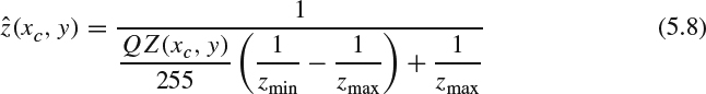
To successfully compress the 3D video using DIBR technology, the depth map should also be compressed to achieve the required compression efficiency. It has been observed that the characteristics of depth map show that: (1) the dynamic range of depth information is scene-dependent and can be very large or very small with different granularity; and (2) the human perceptual system is more sensitive to the depth changes in nearby objects than farther objects. To satisfy the aforementioned requirements and potentially to reuse the existing video coding tools for depth information compression, one promising solution is to quantize the depth map into eight bits, supported in most existing coding tools, according to the inverted real-world depth as follows [21]:
where Zmax and Zmin are the maximum depth and minimum depth in one image. The inverse quantization to decode the depth information is:
Having all real-world depth information converted to quantized inverted real-world depth, QZ, we observe that QZ is smooth or near constant across one object and has sharp transitions between foreground and background. The eight-bit depth map QZ can be treated as a monochromatic, luminance-only image, taking values between 0 and 255, and can be efficiently compressed via existing video codecs (e.g., the MPEG-x codec). As defined in MPEG-C Part 3 [22], the depth information can be treated as auxiliary pixel data to facilitate the backward compatibility with original MPEG codecs.
Bringing in DIBR technology, the left view and right view video can be synthesized via one video sequence and one depth video sequence, as shown in Figure 5.14 [23, 24]. The general video compression algorithm can be applied to the color video and depth video independently. After compression, both bit streams are sent to the receiver, and new views can be synthesized with color and depth information in the display. In general, the required bit rate to encode the depth information is around 10–20% of the compressed color video bit stream such that the decoder has sufficient precision to generate proper stereoscopic images [25].
Although video plus depth coding provides a promising solution, it still has several challenges to overcome. The first major problem is the newly exposed areas (also known as holes) appearing in the synthesized views, as shown in Figure 5.15. Those holes often appear along the object boundaries whose depth values change significantly. The main cause of those holes is that those areas are covered by the foreground objects in the original view but become visible to the new viewpoints. Since those covered pixels are not encoded in the color video sequences, we cannot fill in the color information for those missing pixels in the synthesized views.
Several solutions have been proposed to fill in the missing values for those holes and can be categorized into (1) post-processing techniques and (2) preprocessing techniques [26]. For post-processing solutions, an intuitive method is to horizontally interpolate the holes from its neighbors, regardless of whether neighboring pixels belong to the foreground or the background. However, the interpolated areas will blend the foreground and background objects together and blur the edges. The hole-filling algorithms can be improved by referring to depth information to determine whether a pixel in the boundary belongs to foreground or background and extrapolating those pixels according to the area to which it belongs [27, 28]. The resulting images are shown in Figure 5.16. The extrapolation process can preserve the object boundaries but the filled areas still look unnatural owing to the use of extrapolation. Filling holes by finding the occluded areas along the temporal domain also helps to reduce the artifacts, since those hidden areas may appear in the past or future video frames [29]. For the preprocessing methods, one can try to smooth the depth map along the boundary to alleviate the sharp transition between foreground and background, which reduces the appearance of the occluded areas [30]. However, this approach brings geometrical distortion owing to the smoothed depth map.
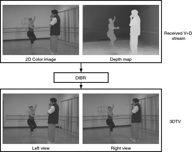
Figure 5.14 Illustration of video plus depth coding.
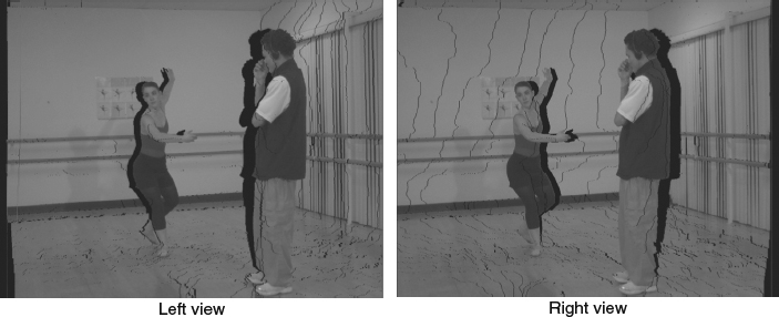
Figure 5.15 Hole artifacts in left view and right view after the DIBR process.
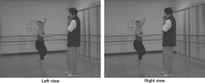
Figure 5.16 Hole filling by extrapolation.
Another important issue is how to encode the depth map to achieve both high fidelity and high compression ratio. The current video plus depth coding approach adopts the existing state-of-the-art video compression technology used for the texture component to compress the depth map. However, the traditional video codecs are optimized to compress nature images. The depth map shows significantly different characteristics from nature images in both spatial and temporal domains.
- In the spatial domain, there are homogeneous or smooth transitions inside scene objects and sharp transitions along the boundaries between different objects. A depth map explicitly captures the 3D structure of a scene by recording the distance between 3D objects and the camera. Because the distance between the camera and object's surfaces generally changes gradually, large portions of typical depth images depicting object surfaces change smoothly. In contrast, the object boundaries, especially the ones separating foreground and background objects of the depth map exhibit abrupt changes as sharp edges. To address these unique characteristics of the depth map, with deployment of H.264 codec it is often observed that the homogeneous regions are encoded with the simplest and largest modes, such as SKIP, Inter 16 × 16 or Intra 16 × 16. It is also observed that the objects' boundaries are often coded with the smallest and simplest prediction mode, such as Intra 4 × 4.
- In the temporal domain, the depth map shows lower consistency than the texture image, namely, the depth value for a static object may vary a lot for consecutive frames. The inconsistency is mainly due to the noise and/or insufficient precision in the depth capture device, or the depth estimation used in stereo matching does not effectively take temporal consistency into consideration. The penalty of inconsistency along the time domain is to have a large amount of residual after motion estimation and to degrade the encoding performance for the P and B-frame type when we compress the depth video using the H.264 codec.
It is important to notice that the depth map is not directly used for viewing. It functions like a predictor during the virtual view synthesis, which is similar to the motion vector used in motion compensation. The encoding artifacts brought by lossy hybrid video codec, such as blocking artifacts along the coding block boundaries and ringing artifacts along the edges, will degrade the depth maps and affect the final quality of the synthesized virtual view, especially on the important edges.
To overcome the rendering artifacts caused by the lossy video codec, techniques adopted to alleviate common compression artifacts can be used to improve the decoded depth map. Introducing in-loop filters specific to depth information improvement in the existing video codec is shown to be a good candidate to suppress the artifacts [31, 32]. Bilateral filter is known as an edge-preserving process in which each pixel is a weighted average from its neighbors within a window and the weighting factor for each neighboring pixel is contributed with consideration of both distance to the central pixel and pixel value difference [33]. Denoting Ip as the pixel value at position p in the depth map, given an N × N window S centered at pixel p, the filtered pixel value can be expressed as follows:

where the G(x, σ) is the Gaussian kernel and has the following formula:
The terms σs and σd are the filter parameters needing to be tuned for best performance and transmitted as metadata for the decoder to conduct the filtering. The first Gaussian kernel weights the distance between pixel p and q, and the second Gaussian kernel weights the pixel value difference between pixel p and q. To maintain a constant DC value before and after the filtering process, the filtered value needs a normalization factor Wp :

The bilateral filter is applied after the depth map is reconstructed from the bit stream. When the bilateral filter is used as an in-loop filter, the filtered reconstructed depth map will be served as reference frames for motion estimation and compensation. The advantage of the in-loop filter is to provide better reference frames to improve the depth map quality. However, the computation load for bilateral filtering on each pixel is high. Introducing the in-loop filter into the codec indicates that the encoder and the decoder need to perform the same operations, which brings more computation complexity into the decoder.
When the window crosses an edge, pixels having similar pixel value can contribute more to the final filtered output, thus preventing the leakage of value from different objects. Owing to the high similarity of structure between the depth map and the color image, one could extend the bilateral filter to a trilateral filter by further considering the pixel value change in the color video information part to reduce depth map coding artifacts while preserving the sharpness of edges and higher spatial coherence [34]. Let Cp be the pixel value at position p in the luminance component of the color video sequence. The trilateral filter can be expressed as:

The normalization factor needs to address the new Gaussian kernel for pixel value difference in the color image:

The processing can be further improved by considering the available information along the time domain, which is commonly used in video processing technologies, such as spatial-temporal noise reduction. One can further build a quad-lateral filter extended from the trilateral filter by further considering temporal variation to improve both the accuracy of the depth map and the temporal consistency [35].
Dedicated approaches, which are not built on top of existing video codecs, are also proposed to handle the unique characteristics of the depth map. To capture the unique characteristics of the depth image, namely, that large parts depicting surfaces contain smoothly changing gray levels and the objects' boundaries exhibit abrupt changes, one could use a piecewise smooth (platelet-based) functions to model a depth image [36]. Two different classes of functions are used to model different areas. The first class is the piecewise-constant function which models the regions with constant depth such as flat unslanted surfaces and contains the following two modes:
- single constant function: approximate each pixel in the whole block by a constant value. This mode requires only one parameter to represent this constant value.
- piecewise constant function (wedgelet function): divide the whole block into two partitions and each pixel in each partition has a constant value. This mode requires three different parameters: one to describe the line to separate a block into two partitions, one to represent the constant value in the first partition, and the third paramter is another a constant value for the second partition.
The second class is the piecewise-linear function which models regions with gradually changing gray level such as ground plane and walls. This class contains the following two modes:
- single linear function: approximate each pixel (x, y) in the whole block by a linear function with three parameters:
- piecewise linear function (platelet-based): divide the whole block into two partitions and each partition has its linear function as (5.14).
The coefficients in each function can be obtained via data fitting to minimize the approximation distortion. For the piecewise constant function and piecewise linear function, we need to determine the partitioning lines and surface parameters. A full search method can be deployed by testing all possible lines and the corresponding optimal parameters. To provide finer granularity for modeling different size of objects and backgrounds to the required level of fidelity, a quad-tree decomposition to hierarchically divide the image into blocks is adopted. The quad-tree decomposition is conducted recursively until the R-D performance cannot be further improved. In each iteration, for each parent block, we can calculate the optimal parameters for each function and choose the function which achieves the best R-D performance. Then, we can further divide this block into four child blocks. For each child block, we can conduct the same procedure to select the best function. If the overall R-D performance from these four child blocks is better than that of the parent block, the parent block will be decomposed into four child blocks. The aforementioned quad-tree decomposition procedure will be conducted recursively for each child block. Otherwise, the decomposition for this parent block is terminated. Although the R-D performance of the depth map coding using platelet-based method is worse than H.264 based depth map coding, the R-D performance of the synthesized view using the platelet-based method is better than H.264 based depth map coding owing to the sharp edge preservation.
In [37], the R-D performance of the depth video can be further improved via adaptive geometry based intra-prediction. The performance gain is contributed to by the following factors:
- The accuracy of the partitioning curves plays an important role in preserving the sharpness of the boundary. To improve the partitioning accuracy using linear line, edge detection followed by Hough transform technology is introduced.
- The object's boundary in one block is often a higher order curve. Partitioning a block by a linear line may not be sufficient to represent two regions separated by the boundary. To have a better approximation, further sub-block partitioning is needed to make the approximation close to the original boundary. On the other hand, further partitioning means more compression overhead to transmit the side information. The R-D performance can be improved by deploying a higher order curve (such as an arc) to partition a block.
- As commonly used in H.264, intra-prediction can bring coding gain owing to the higher spatial correlation among neighboring blocks. After the partitioning is done for each block, each sub-block can be predicted from its available neighboring reconstructed blocks. By doing so, the residual in each block is reduced and thus bit rate can be reduced.
To resolve the issue of depth variation in the depth map along the time domain, namely inconsistent depth values for static objects for consecutive depth frames which causes low coding efficiency for inter-prediction, an object-adaptive depth compensated inter-prediction method is proposed in [38]. It is observed that the depth value of each object in the reference frame has a roughly constant depth offset compared to the corresponding object in the current frame. The inter-prediction error can be significantly reduced when both the object partitions/boundaries are precisely found in the time domain and the depth offsets are compensated for each object. Two key components are introduced to address these unique characteristics:
- A threshold-based algorithm to separate foreground and background is conducted via a bi-section search within each block. An initial threshold is selected by taking the average of the maximum and minimum depth value in one block. The foreground and background are chosen by selecting the pixels whose depth value is no less than and less than this threshold, respectively. The new threshold is constructed by taking the average of the mean depth value of the foreground and the mean depth value of the background. If the new threshold is different from the old threshold, we will partition the foreground and the background again according to this new threshold. This process is repeated until there is no change between the new and old threshold. The foreground and background partitioning algorithm will be deployed for both the reference block (in the reference frame) and the current block (in the current frame). The depth offset are calculated by taking the difference between the mean of depth values in the partition of the reference block and the mean of depth values in the corresponding partition of the current block. Note that the depth offset should be conducted for both foreground and background.
- The tradition motion estimation methods often fail to find the true motion vectors when the mean depth values are shifted between reference and current block. One possible improved motion estimation method is to conduct the motion vector search based on the mean-removal distortion measurement. In other words, the MAD measurement used in (5.1) is modified as follows:

where
 and
and  are the mean depth pixel value in the current and reference block, respectively. The alternative to address the depth map motion estimation is to conduct the motion estimation based on the edge map obtained from the depth map. This is because the edge map already contains the information of the object's boundaries (as edges) and also removes the mean depth values.