
8.4 Unequal Error Protection
As mentioned earlier in this chapter, in a video communication system, the output of the source encoder is a bit stream that usually has different parts and a great deal of structure. Within the bit stream, headers and markers separate frames and group of frames. But even beyond this structure, there is a structure within the source encoded bit stream corresponding to a single frame. Within this portion of the bit stream it is usually possible to recognize different parts corresponding to the different outputs from the source encoder operation. For example, it will usually be possible to recognize a part composed of entropy-coded information resulting from the compression of a frame texture, if it is an intra-predicted frame, or resulting from the compression of a motion compensated prediction error frame if the frame is not intra-predicted. Within the source encoded bit stream for non-intra-predicted frames it will be possible to find, for example, another part containing the motion vector information, which is frequently encoded using differential encoding.
In essence, the different parts of the compressed video bit stream result in different reconstruction distortion after being affected by channel errors. To reduce the likelihood of these errors happening, it is necessary to add forward error control (FEC) to the compressed video bit stream. This implies adding redundant bits that will help identify and correct some errors. Since these added redundancy bits will increase the bit rate required to transmit the video, they bring the problem of how much error protection redundancy to add. Adding enough redundancy so as to have the strong error correcting code required by those parts of the bit stream that yield the most distortion would result in an inefficient excess of redundancy for the other parts. Adding redundancy matched to the average error-related distortion performance between all the parts of the bit stream is both excessive for the parts that need little error protection and insufficient for the parts that need the most error protection. Of course, adding a small amount of redundancy, such as that usually needed by most of the parts of the bit stream, may be cheap in terms of transmission bit rate increase but would result in severe distortion of those few parts requiring a lot more error protection. In summary, the best approach in terms of striking the best tradeoff between distortion performance and added error control redundancy is to assign different levels of error protection to the different parts of the source encoded bit stream, according to the impact that the channel errors on that part would have on the end-to-end distortion. This assignment of different error protection to different parts of the source encoded bit stream is a technique called “unequal error protection” (UEP).
With 3D video, different frames have different importance, depending on their temporal dependency and the effects that their loss or corruption produces. For example, I-frames are the most important of all frames because their loss will propagate error into the reconstruction of all dependent P-frames. Also, if P-frames from a view, say, the right view, are used to predict and differentially encode the other view, then it is more important for these frames to be received with no errors. These observations, common to 3D video, naturally lend themselves to a UEP error protection scheme design. This is the problem approached in [10], where both a rate-distortion optimized and a UEP protection scheme are designed for a 3D video codec derived from the H.264 codec. A simplified block diagram, showing the configuration for this video codec is shown in Figure 8.10.

Figure 8.10 Simplified block diagram for the H.264-based 3D video encoder and decoder from [11].
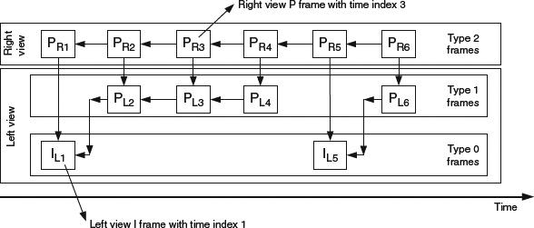
Figure 8.11 Frames types and their interdependency for the H.264-based 3D video encoder and decoder from [11].
Figure 8.10 shows a typical configuration for a video codec that outputs I-frames and P-frames, implemented with the H.264 codec, but now expanded to provide 3D functionality by adding a decoded picture buffer that allows differential encoding of one view based on the other view. The interdependency of the different frames is shown in Figure 8.11. The figure introduces, for ease of discussion, a classification of frames into three different types. Frames of different types have different importance. As such, frames of type 0 are the most important ones because their loss affects all P-frames from both views. Frames of type 1 (left view, P-frames) are second in importance because their loss affects P-frames from both views. Frames of type 2 (right view, P-frames) are the least important ones because their loss only affects other frames of the same type.
As mentioned, the design in [10] follows two main steps. In the first step, the video encoding rate is calculated for the three types of frames using as a criterion the minimization of the overall distortion subject to total rate limitations. This step of the design is the well-known problem of using knowledge of the rate-distortion (RD) source codec curve to do bit rate allocation so as to minimize distortion. The different twist to this problem is the presence of the different views from the 3D view. Nevertheless, considering the different views is not too different from considering the different predictive types of frames in 2D video. To solve this design problem, it is necessary to derive first the RD curve. In [10], this is done by extending the model for 2D RD curves. Consequently, the RD curve for a type 0 frame is found to be:
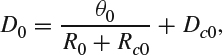
where D0 is the distortion of a type 0 frame when encoding at a rate R0. The variables θ0, Rc0 and Dc0 are coded-specific adjustment values for the model that need to be calculated through simulations and curve fitting. Similarly, the RD curve for a type 1 frame is:
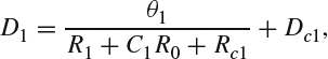
where D1 is the distortion of a type 1 frame when encoding at a rate R1, and θ1, C1, Rc1, and Dc1 are the adjustment variables that need to be computed to match the model to the codec performance. Note that the RD curve for a type 1 frame depends also on the rate used for type 0 frames, making explicit the need of type 0 frames in the encoding and decoding of type 1 frames. Finally, and reasoning in the same way, the RD curve for a type 2 frame is:
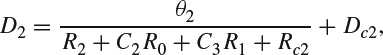
where D2 is the distortion of a type 2 frame when encoding at a rate R2, and θ2, C2, C3, Rc2, and Dc2 are the adjustment variables that need to be computed to match the model to the codec performance. Knowing the RD performance from the three types of frames allows calculating the total RD model:
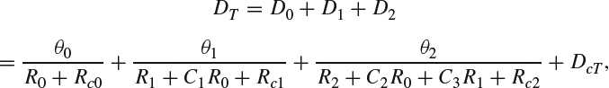
where DcT = Dc0 + Dc1 + Dc2. With this intermediate result it is now possible to write the rate allocation design problem:
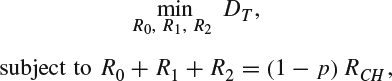
where p is the proportional increase in bit rate due to the added redundancy and RCH is the total bit rate supported for transmission over the channel. One of the advantages of the model used for DR function is that the design problem can be solved using simply the Lagrange multiplier method. The result is the optimal allocation of encoding rate to each type of frame. In the above formulation, one possible debatable assumption is whether the total distortion can actually be assumed to be equal to the sum of distortions from each frame type DT = D0 + D1 + D2. As it turns out, it is possible to make this assumption in this case, as results presented in [10] show that the result from the Lagrange multiplier based rate assignment is very close to the optimal solution.
The 3D video codec in this case retains many of the characteristics and structure of the H.264 video codec because it was implemented as an adaptation from it. In particular, the output from the encoder is organized into data packets called the “network abstraction layer” (NAL). Losing a NAL unit during transmission means losing a number of macroblocks from a type 0, type 1, or type 2 frame. Yet, as discussed earlier, the effect of losing a NAL unit is more important when the NAL unit contains macroblock data from a type 0 frame rather than from a type 1 frame and even less important if the macroblock contains data from a type 2 frame. Therefore, a UEP scheme that considers this effect will achieve a more efficient redundancy allocation. In [10] this is done by first calculating the average distortion linked with losing a NAL unit associated with each of the three frames types. For NAL units associated with type 0 frames, the average distortion DL0 is the mean squared difference between the original macroblocks and their replacement using spatial error concealment. For NAL units associated with type 1 and type 2 frames, the average distortions DL1 and DL2 are the mean squared difference between the original macroblocks and their replacement using temporal error concealment. With this result, the UEP design problem consists of distributing redundancy between the three frame types. Formally, this can be written as:

where p0, p1, and p2 are the proportion of the bit rate allocated to frame types 0, 1, and 2, respectively, used for redundancy. Also, P0, P1, and P2 are the loss probability for frame types 0, 1, and 2, respectively, and which depend on the FEC technique used and the channel conditions and parameters. Note that in the expression for the problem formulation:
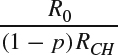
is the probability that a NAL unit is associated with a type 0 frame,

is the probability that a NAL unit is associated with a type 1 frame, and
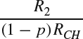
is the probability that a NAL unit is associated with a type 2 frame. The constraint p0R0 + p1R1 + p2R2 = pRCH in the UEP design formulation expresses that the combined redundancy from NAL units associated with all the frame types should equal the total transmitted redundancy.
The error protection in [10] is implemented using systematic Raptor codes, [12]. With this setting, the UEP scheme shows 3–8 dB improvement in PSNR when compared to the equivalent scheme with no UEP (the redundancy is distributed evenly among the three types of frames) and is approximately 4 dB away from the PSNR performance with no channel errors.