
CHAPTER 16
Creating and Applying Standard Materials
Using standard materials
Learning the various shaders
Exploring the Material rollouts
Applying materials to scene objects
Now that you've learned the basic material properties and acquainted yourself with the Material Editor and the Material/Map Browser, this chapter gives you a chance to create some simple original materials and apply them to objects in the scene. The simplest material is based on the Standard material type, which is the default material type.
Using the Standard Material
Standard materials are the default Max material type. They provide a single, uniform color determined by the Ambient, Diffuse, Specular, and Filter color swatches. Standard materials can use any one of several different shaders. Shaders are algorithms used to compute how the material should look, given its parameters.
Standard materials have parameters for controlling highlights, opacity, and self-illumination. They also include many other parameters sprinkled throughout many different rollouts. With all the various rollouts, even a standard material has an infinite number of possibilities.
Using Shading Types
Max includes several different shader types. These shaders are all available in a drop-down list in the Shader Basic Parameters rollout at the top of the Parameter Editor panel in the Slate Material Editor. The Slate Material Editor is opened using the Rendering ![]() Material Editor
Material Editor ![]() Slate Material Editor menu command or by pressing the M key. Each shader type displays different options in its respective Basic Parameters rollout. Figure 16.1 shows the basic parameters for the Blinn shader. Other available shaders include Anisotropic, Metal, Multi-Layer, Oren-Nayar-Blinn, Phong, Strauss, and Translucent Shader.
Slate Material Editor menu command or by pressing the M key. Each shader type displays different options in its respective Basic Parameters rollout. Figure 16.1 shows the basic parameters for the Blinn shader. Other available shaders include Anisotropic, Metal, Multi-Layer, Oren-Nayar-Blinn, Phong, Strauss, and Translucent Shader.
Cross-Reference
The Material/Map Browser holds all the various material types. The other material types are covered in Chapter 18, “Creating Compound Materials and Using Material Modifiers,” and Chapter 30, “Using Specialized Material Types.”
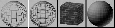
The Shader Basic Parameters rollout also includes several options for shading the material, including Wire, 2-Sided, Face Map, and Faceted, as shown in Figure 16.1. Wire mode causes the model to appear as a wireframe model. The 2-Sided option makes the material appear on both sides of the face and is typically used in conjunction with the Wire option or with transparent materials. The Face Map mode applies maps to each single face on the object. Faceted ignores the smoothing between faces.
Note
Using the Wire option or the 2-Sided option is different from the wireframe display option in the viewports. The Wire and 2-Sided options define how the object looks when rendered.
FIGURE 16.1 Basic parameter options include (from left to right) Wire, 2-Sided, Face Map, and Faceted.
Blinn shader
This shader is the default. It renders simple circular highlights and smoothes adjacent faces.
The Blinn shader includes color swatches for setting Ambient, Diffuse, Specular, and Self-Illumination colors. To change the color, click the color swatch and select a new color in the Color Selector dialog box.
Note
You can drag colors among the various color swatches. When you do so, the Copy or Swap Colors dialog box appears, which enables you to copy or swap the colors.
You can use the Lock buttons to the left of the color swatches to lock the colors together so that both colors are identical and a change to one automatically changes the other. You can lock Ambient to Diffuse and Diffuse to Specular.
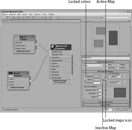
The small, square buttons to the right of the Ambient, Diffuse, Specular, Self-Illumination, Opacity, Specular Level, and Glossiness controls are shortcut buttons for adding a map in place of the respective parameter. Clicking these buttons opens the Material/Map Browser, where you can select the map type. You can also lock the Ambient and Diffuse maps together with the lock icon to the right of the map buttons. The Ambient and Diffuse colors are locked together by default.
When a map is loaded and active, it appears in the Maps rollout, and an uppercase letter M appears on its button. When a map is loaded but inactive, a lowercase m appears. After you apply a map, these buttons open to make the map the active level and display its parameters in the rollouts. Figure 16.2 shows these map buttons.
Cross-Reference
For more on maps and the various map types, see Chapter 17, “Adding Material Details with Maps.”
FIGURE 16.2 The Blinn Basic Parameters rollout lets you select and control properties for the Blinn shader.
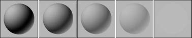
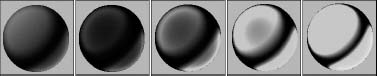
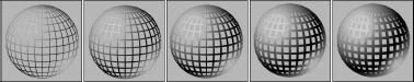
Self-Illumination can use a color if the Color option is enabled. If this option is disabled, a spinner appears that enables you to adjust the amount of default color used for illumination. Materials with a Self-Illumination value of 100 or a bright color like white lose all shadows and appear to glow from within. This happens because the self-illumination color replaces the ambient color, but a material with self-illumination can still have specular highlights. To remove the effect of Self-Illumination, set the spinner to 0 or the color to black. Figure 16.3 shows a sphere with Self-Illumination values (from left to right) of 0, 25, 50, 75, and 100.
FIGURE 16.3 Increasing the Self-Illumination value reduces the shadows in an object.
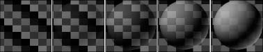
The Opacity spinner sets the level of transparency of an object. A value of 100 makes a material completely opaque, while a value of 0 makes the material completely transparent. Use the Background button (located on the upper-right side of the Material Editor) to enable a patterned background image to make it easier to view the effects of the Opacity setting. Figure 16.4 shows materials with Opacity values of 10, 25, 50, 75, and 90.
FIGURE 16.4 The Opacity value sets how transparent a material is.
Specular highlights are the bright points on the surface where the light is reflected at a maximum value. The Specular Level value determines how bright the highlight is. Its values can range from 0, where there is no highlight, to 100, where the highlight is at a maximum. The graph to the right of the values displays the intensity per distance for a cross section of the highlight. The Specular Level defines the height of the curve or the value at the center of the highlight where it is the brightest. This value can be overloaded to accept numbers greater than 100. Overloaded values create a larger, wider highlight.
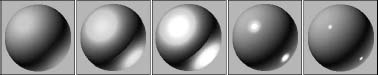
The Glossiness value determines the size of the highlight. A value of 100 produces a pinpoint highlight, and a value of 0 increases the highlight to the edges of the graph. The Soften value doesn't affect the graph, but it spreads the highlight across the area defined by the Glossiness value. It can range from 0 (wider) to 1 (thinner). Figure 16.5 shows a sampling of materials with specular highlights. The left image has a Specular Level of 20 and a Glossiness of 10, the second image has the Specular Level increased to 80, the third image has the Specular Level overloaded with a value of 150, and the last two images have the Glossiness value increased to 50 and 80, respectively.
FIGURE 16.5 You can control specular highlights by altering brightness and size.
Phong shader
The Phong shader creates smooth surfaces like Blinn without the quality highlights, but it renders more quickly than the Blinn shader does. The parameters for the Phong shader are identical to those for the Blinn shader. The differences between Blinn and Phong are very subtle, but Blinn can produce highlights for lights at low angles to the surface, and its highlights are generally softer.
Tip
The Blinn shader is typically used to simulate softer materials like rubber, but the Phong shader is better for hard materials like plastic.
Anisotropic shader
The Anisotropic shader is characterized by noncircular highlights. The Anisotropy value is the difference between the two axes that make up the highlight. A value of 0 is circular, but higher values increase the difference between the axes, and the highlights are more elliptical.
Most of the parameters for this shader are the same as those for the Blinn shader, but several parameters of the Anisotropic type are unique. The Diffuse Level value determines how bright the Diffuse color appears. This is similar to Self-Illumination, but it doesn't affect the specular highlights or the shadows. Values can range from 0 to 400.
Compared with the Blinn shader, the Specular Highlight graph looks very different. That is because it displays two highlight components that intersect at the middle. The Specular Level value still controls the height of the curve, and the Glossiness still controls the width, but the Anisotropy value changes the width of one axis relative to the other, creating elliptical highlights. The Orientation value rotates the highlight. Figure 16.6 compares the Specular Highlight graphs for the Blinn and Anisotropic shaders.
Tip
Because the Anisotropy shader can produce elliptical highlights, it is often used on surfaces with strong grooves and strands, like fabrics and stainless steel objects.
FIGURE 16.6 The Specular Highlight graph for the Blinn and Anisotropic shaders
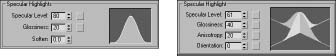
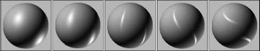
Figure 16.7 shows several materials with the Anisotropic shader applied. The first three images have Anisotropic values of 30, 60, and 90, and the last two images have Orientation values of 30 and 60.
FIGURE 16.7 Materials with the Anisotropic shader applied have elliptical highlights.
Multi-Layer shader
The Multi-Layer shader includes two Anisotropic highlights. Each of these highlights can have a different color. All parameters for this shader are the same as the Anisotropic shader described previously, except that there are two Specular Layers and one additional parameter: Roughness. The Roughness parameter defines how well the Diffuse color blends into the Ambient color. When Roughness is set to a value of 0, an object appears the same as with the Blinn shader, but with higher values, up to 100, the material grows darker.
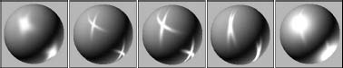
Figure 16.8 shows several materials with a Multi-Layer shader applied. The first two images have two specular highlights, each with an Orientation value of 60 and Anisotropy values of 60 and 90. The third image has an increased Specular Level of 110 and a decrease in the Glossiness to 10. The fourth image has a change in the Orientation value for one of the highlights to 20, and the final image has a drop in the Anisotropy value to 10.
Tip
The Multi-Layer shader is useful to give a material a sense of surface depth. For example, it can give the illusion of a layer of shellac on wood or a layer of wax on tile.
FIGURE 16.8 Materials with a Multi-Layer shader applied can have two crossing highlights.
Oren-Nayar-Blinn shader
The Oren-Nayar-Blinn shader is useful for creating materials for matte surfaces such as cloth and fabric. The parameters are identical to the Blinn shader, with the addition of the Diffuse Level and Roughness values.
Metal shader
The Metal shader simulates the luster of metallic surfaces. The Highlight curve has a shape that is different from that of the other shaders. It is rounder at the top and doesn't include a Soften value. It can also accept a much higher Specular Level value (up to 999) than the other shaders. Also, you cannot specify a Specular color. All other parameters are similar to those of the Blinn shader. Figure 16.9 shows several materials with the Metal shader applied. These materials differ in Specular Level values, which are (from left to right) 50, 100, 200, 400, and 800.
Note
For the Metal shader, the specular color is always the same as the material's diffuse color.
FIGURE 16.9 A material with a Metal shader applied generates its own highlights.
Strauss shader
The Strauss shader provides another alternative for creating metal materials. This shader has only four parameters: Color, Glossiness, Metalness, and Opacity. Glossiness controls the entire highlight shape. The Metalness value makes the material appear more metal-like by affecting the primary and secondary highlights. Both of these values can range between 0 and 100.
Tip
The Strauss shader is often better at making metal than the Metal shader because of its smoothness value and the ability to mix colors with the Metalness property.
Translucent shader
The Translucent shader allows light to easily pass through an object. It is intended to be used on thin, flat plane objects, such as a bedsheet used for displaying shadow puppets. Most of the settings for this shader are the same as the others, except that it includes a Translucent color. This color is the color that the light becomes as it passes through an object with this material applied. This shader also includes a Filter color and an option for disabling the specular highlights on the backside of the object.
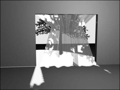
Tutorial: Making curtains translucent
The Translucent shader can be used to create an interesting effect. Not only does light shine through an object with this shader applied, but shadows also are visible.
To make window curtains translucent, follow these steps:
- Open the Translucent curtains.max file from the Chap 16 directory on the CD.
This file contains a simple scene of a tree positioned outside a window.
- Open the Material Editor by choosing Rendering
 Material Editor Slate Material Editor, by clicking the Material Editor button on the main toolbar, or by pressing the M key.
 - In the Material/Map Browser panel of the Material Editor, double-click on the Standard material, then select the material block node, and in the Name field, name the material Curtains. Select the Translucent Shader from the Shader Basic Parameters rollout. Click the Diffuse color swatch, and select a light blue color. Click the Close button to exit the Color Selector.
- Click the Translucent Color swatch, change its color to a light gray, and set the Opacity to 75.
- Drag the Curtains material's output node socket onto the curtain object in the Left viewport or select the curtains in the viewport and use the Assign Material to Selection button in the toolbar.
Figure 16.10 shows the resulting image. Notice that the tree's shadow is cast on the curtains.
FIGURE 16.10 These translucent window curtains show shadows.
Accessing Other Parameters
In addition to the basic shader parameters, several other rollouts of options can add to the look of a material.
Extended Parameters rollout
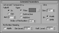
The Material Editor includes several settings, in addition to the basic parameters, that are common for most shaders. The Extended Parameters rollout, shown in Figure 16.11, includes Advanced Transparency, Reflection Dimming, and Wire controls. All shaders include these parameters.
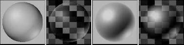
You can use the Advanced Transparency controls to set the Falloff to be In, Out, or a specified Amount. The In option increases the transparency as you get farther inside the object, and the Out option does the opposite. The Amount value sets the transparency for the inner or outer edge. Figure 16.12 shows two materials that use the Transparency Falloff options on a gray background and on a patterned background. The two materials on the left use the In option, and the two on the right use the Out option. Both are set at Amount values of 100.
FIGURE 16.11 The Extended Parameters rollout includes Advanced Transparency, Reflection Dimming, and Wire settings.
Tip
If you look closely at a glass sphere, you'll notice that the glass is thicker when you look through the edge of the sphere than through the sphere's center. This can be created using the In option in the Advanced Transparency section.
FIGURE 16.12 Materials with the In and Out Falloff options applied
The three transparency types are Filter, Subtractive, and Additive. The Filter type multiplies the Filter color with any color surface that appears behind the transparent object. With this option, you can select a Filter color to use. The Subtractive and Additive types subtract from or add to the color behind the transparent object.
The Index of Refraction is a measure of the amount of distortion caused by light passing through a transparent object. Different physical materials have different Index of Refraction values. The amount of distortion also depends on the thickness of the transparent object. The Index of Refraction for water is 1.33 and for glass is 1.5. The default of 1.0 has no effect.
The Wire section lets you specify a wire size or thickness. Use this setting if the Wire option or the 2-Sided option is enabled in the Shaders Basic Parameters rollout. The size can be measured in either Pixels or Units. Figure 16.13 shows materials with different Wire values from 1 to 5 pixels.
FIGURE 16.13 Three materials with Wire values of (from left to right) 1, 2, 3, 4, and 5 pixels
Reflection Dimming controls how intense a reflection is. You enable it by using the Apply option. The Dim Level setting controls the intensity of the reflection within a shadow, and the Refl Level sets the intensity for all reflections not in the shadow.
SuperSampling rollout
Pixels are small square dots that collectively make up the entire screen. At the edges of objects where the material color changes from the object to the background, these square pixels can cause jagged edges to appear. These edges are called artifacts and can ruin an image. Anti-aliasing is the process through which these artifacts are removed by softening the transition between colors.
Max includes anti-aliasing filters as part of the rendering process. SuperSampling is an additional anti-aliasing pass that can improve image quality that is applied at the material level. You have several SuperSampling methods from which to choose. The SuperSampling method can be defined in the Material Editor, or you can choose the settings in the Default Scanline Renderer rollout of the Render Scene dialog box by enabling the Use Global Settings option.
Note
Anti-aliasing happens before raytracing when rendering, so even if the anti-aliasing option is enabled, the reflections and/or refractions will still be aliased.
Cross-Reference
For more about the various anti-aliasing filters, see Chapter 23, “Rendering a Scene and Enabling Quicksilver.”
SuperSampling is calculated only if the Anti-Aliasing option in the Render Scene dialog box is enabled. The raytrace material type has its own SuperSampling pass that is required in order to get clean reflections.
Note
Using SuperSampling can greatly increase the time it takes to render an image.
In a SuperSampling pass, the colors at different points around the center of a pixel are sampled. These samples are then used to compute the final color of each pixel. The SuperSampling settings can be set globally in the Render Setup dialog box or for each material individually by disabling the Use Global Settings option. These four SuperSampling methods are available:
- Adaptive Halton: Takes semirandom samples along both the pixel's X-axis and Y-axis. It takes from 4 to 40 samples.
- Adaptive Uniform: Takes samples at regular intervals around the pixel's center. It takes from 4 to 26 samples.
- Hammersley: Takes samples at regular intervals along the X-axis, but takes random samples along the Y-axis. It takes from 4 to 40 samples.
- Max 2.5 Star: Takes four samples along each axis.
The first three methods enable you to select a Quality setting. This setting specifies the number of samples to be taken. The more samples taken, the higher the resolution, but the longer it takes to render. The two Adaptive methods (Adaptive Halton and Adaptive Uniform) offer an Adaptive option with a Threshold spinner. This option takes more samples if the change in color is within the Threshold value. The SuperSample Texture option includes maps in the SuperSampling process along with materials.
Tip
To get good reflections and refractions, enable SuperSampling for final renders.
Maps rollout
A map is a bitmap image that is wrapped about an object. The Maps rollout includes a list of the maps that you can apply to an object. Using this rollout, you can enable or disable maps, specify the intensity of the map in the Amount field, and load maps. Clicking the Map buttons opens the Material/Map Browser where you can select the map type.
Cross-Reference
Find out more about maps in Chapter 17, “Adding Material Details with Maps.”
Caution
These dynamic properties are used only with the Dynamic utility. reactor is a more versatile and robust dynamics solution, making these properties obsolete; they are included only for backward compatibility.
DirectX Manager rollout
The DirectX Manager rollout lets you display the current material in the viewport as a DirectX shader when the DX Display of Standard Material option is enabled. The current material also can be saved as an .fx material file. Many game engines render using DirectX, so this option lets you view your materials in the viewport as they will appear within the game.
Caution
The DirectX Manager rollout isn't available by default. It appears only when the Direct3D display driver is selected.
At the bottom of the DirectX Manager rollout is a drop-down list for selecting to use the available DirectX shaders. The two available DirectX shaders are LightMap and Metal Bump 9. These shaders are generic, so they can be used on many different types of objects. The Light Map shader includes a parameter for loading a custom light map, and the Metal Bump 9 shader includes parameters for specifying two texture maps; specularity; and normal, bump, and reflection maps.
mental ray connection rollout
The mental ray connection rollout includes options for enabling different properties that are used by the mental ray rendering engine. The properties include Surface and Shadow Shaders, Photon and Photon Volume, and Extended Shaders and Advanced Shaders, including Contour and Light Map.
Cross-Reference
The mental ray rendering engine and its properties are covered in Chapter 47, “Rendering with mental ray and iray.”
Tutorial: Coloring a dolphin
As a quick example of applying materials, you'll take a dolphin model created by Zygote Media and position it over a watery plane. You then apply custom materials to both objects.
To add materials to a dolphin, follow these steps:
- Open the Dolphin.max file from the Chap 16 directory on the CD.
This file contains a simple plane object and a dolphin mesh.
- Open the Material Editor by choosing Rendering Material Editor Slate Material Editor, clicking the Material Editor button on the main toolbar, or pressing the M key.
- In the Material/Map Browser panel, double-click on the Standard material; select the standard material block and, in the Name field in the Parameter Editor panel, rename the material Dolphin Skin. Click the Diffuse color swatch, and select a light gray color. Then click the Specular color swatch, and select a light yellow color. Click the Close button to exit the Color Selector. In the Specular Highlights section, increase the Specular Level to 45.
- Double-click on the Standard material in the Material/Map Browser again and name it Ocean Surface. Click the Diffuse color swatch, and select a light blue color. Set the Specular Level and Opacity values to 80. In the Maps rollout, click the None button to the right of the Bump selection. In the Material/Map Browser that opens, double-click the Noise selection in the Maps rollout. Click on the Noise map button to access the Noise parameters, and then enable the Fractal option and set the Size value to 15 in the Noise Parameters rollout.
- Select the dolphin body in the viewport and, with the Dolphin Skin material selected in the Material Editor, click the Assign Material to Selection button in the Material Editor toolbar. Then do the same for the ocean surface.
Note
This model also includes separate objects for the eyes, mouth, and tongue. These objects could have different materials applied to them, but they are so small in this image that you won't worry about them.
- Choose Rendering Environment (keyboard shortcut, 8), click the Background Color swatch, and change it to a light sky blue.
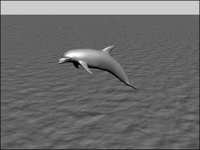
Figure 16.14 shows the resulting image.
FIGURE 16.14 A dolphin over the water with applied materials
Summary
This chapter presented the Standard material and gave you a chance to create some simple original materials.
In this chapter, you did the following:
- Learned about various material types
- Discovered and learned to use the various material parameters
- Discovered the basics of using standard materials
- Learned how to use the various shaders
- Explored the other Material rollouts
- Learned to apply materials to a model
This chapter should have been enough to whet your appetite for materials, and yet it really covered only one part of the equation. The other critical piece for materials is maps, and you'll dive into those in the next chapter.