
CHAPTER 43
Simulating Physics-Based Motion with MassFX
Exploring the MassFX tools
Setting object type and running simulations
Assigning object properties
Setting collision mesh type
Using constraints
Baking animation keys
When you speak of MassFX in Max, you really are speaking of physics. Physics is one of the coolest arms of science because it deals with the science of matter and energy and includes laws that govern the motions and interactions between objects. For animators, this is great news because what you are trying to do is to animate the motions and interactions between objects.
So, should all animators study physics? The answer is absolutely. Understanding these laws through study and experience will sharpen your animating skills. But you can also take advantage of the work that other animators have done in understanding the laws of physics and turning them into a product that ships with Max. The other animators are the PhysX group at NVIDIA, and the product is MassFX.
The MassFX physics engine included in Max is the same engine commonly used in games to simulate game-world physics.
Using MassFX, you can simulate many physical properties like density, mass, and friction and automatically capture keyframes as the objects interact. It's like getting a physics degree for free.
The MassFX tools include everything you need to access the MassFX physics simulation engine. After physical properties are defined, you can define physical forces to act on these objects and simulate the resulting animation. Not only does MassFX make difficult physical motions realistic, but it also is fun to play with.
Understanding Dynamics
Dynamics is a branch of physics that deals with forces and the motions they cause, and regardless of your experience in school, physics is your friend—especially in the world of 3D. Dynamics in Max can automate the creation of animation keys by calculating the position, rotation, and collisions between objects based on physics equations.
Consider the motion of a simple yo-yo. Animating this motion with keys is fairly simple: Set rotation and position keys halfway through the animation and again at the end, and you're finished.
Now think of the forces controlling the yo-yo. Gravity causes the yo-yo to accelerate toward the ground, causing the string to unwind, which makes the yo-yo spin about its axis. When it reaches the end of the string, the rotation reverses and the yo-yo rises. Using Gravity and Motor Space Warps, you can simulate this motion, but setting the keys manually is probably easier for these few objects.
But before you write off dynamics, think of the motion of popcorn popping. With all the pieces involved, setting all the position and rotation keys would take a long time. For this system, using dynamics makes sense.
Dynamic tools let you specify objects to include in a simulation, the forces they interact with, and the objects to be involved in collisions. After the system is defined, the Dynamics utility automatically calculates the movement and collisions of these objects according to the forces involved, and then it sets the keys for you.
New Feature
The MassFX system is new to 3ds Max 2012.
Note
MassFX isn't the first physic-based system available in Max. Early versions of Max had a Dynamics utility, and recently dynamics were possible using Max's reactor system. These early systems have been replaced by MassFX, which is easier to use and much more robust than earlier versions.
Using MassFX
The MassFX plug-in was developed by a company named PhysX, which is now part of NVIDIA. MassFX is a complex piece of software with a huge assortment of features that enable you to define physical properties and forces and have the scene automatically generate the resulting animation keys as the objects interact while following the laws of physics.
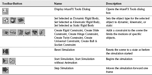
The MassFX plug-in interface can be accessed from a simple toolbar that's opened using the right-click pop-up menu on any toolbar. The toolbar is named MassFX, shown in Figure 43.1, and it is surprisingly simple, consisting of only five buttons. With the MassFX toolbar, you can open the MassFX Tools dialog box, define objects and constraints to include in the simulation, and control the simulation. The toolbar also includes several flyout tools that are described in Table 43.1.
FIGURE 43.1 Use the MassFX toolbar to open the MassFX Tools dialog box and define and control simulations.
![]()
TABLE 43.1 MassFX Toolbar Buttons
The MassFX commands also are available as menu options in the Animation ![]() Simulation–MassFX menu.
Simulation–MassFX menu.
The MassFX process
Before getting into the details of MassFX, I want to briefly explain the process involved in using this feature. MassFX works with geometry that is defined with certain physical properties. After these properties are defined, the MassFX engine can take over and determine how all the various objects interact with one another.
The first step is to assign each object to be included in the simulation an object type. These can be either Dynamic, Kinematic, or Static. Dynamic objects are ones that are included in the simulation, Kinematic objects apply forces to the simulation and can be changed to a Dynamic object to interact with other objects, but Static objects don't move and provide the walls and floor for the objects to crash against.
In addition to the object type, you can specify values for the object's Density, Mass, Friction, and Bounciness using the MassFX Tools dialog box. More on these values is presented later in this chapter.
When an object is assigned a type, it automatically assumes a proxy shape that surrounds the object that is used to calculate any collisions. To keep the simulation calculations simple, this default proxy shape is usually a simple box or sphere. MassFX allows you to use a more complex collision mesh, but doing so compounds the simulation calculations and should be used sparingly. Within the Edit panel of the MassFX Tools dialog box are several options for defining the collision mesh, including a tool to generate a custom collision mesh based on the object's geometry.
Establishing the simulation properties
The MassFX Tools dialog box, shown in Figure 43.2, is opened using the first button in the MassFX toolbar. The MassFX Tools dialog box holds the settings for the World values. These World values are the global settings for the simulation. The global values defined in the World panel apply to all objects included in the simulation, but these global values can be changed for each individual object using the settings in the Edit panel.
FIGURE 43.2 The MassFX Tools dialog box includes World settings.
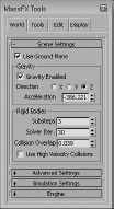
By default, the ground plane acts as a static object, and gravity is enabled. You can change the value of gravity and even make it a positive value so objects float upward using the settings in the World panel.
The number of Substeps determines the amount of calculations that the simulation goes through. Generally, the higher the Substeps value, the more accurate the simulation collisions and the longer it takes to complete. This is also impacted by the Solver Iterations. More Solver Iterations are needed for simulations involving a lot of constraints and collisions, but a value larger than 30 is overkill.
The Collision Overlap value is the amount of overlap between collision meshes that is allowed. If this is set to 0, the objects can jitter about erratically, but values too high will allow the objects to penetrate each other noticeably.
If you know that some objects, such as a projectile, will travel very fast, you can enable the Use High Velocity Collisions option. This option uses a different algorithm that prevents gross overlapping of surfaces for high velocity objects.
Within the Advanced Settings rollout, you can set the minimum speed and spin values for the Sleep, High Velocity, and Bounce settings. These settings are global for all objects in the simulation unless overwritten by a setting for the individual object.
The Simulation Settings rollout includes several options that define what to do when the last frame of the animation is reached. The options are to simply continue the simulation. Be aware that any motion beyond the last frame will not be captured if you bake the motion down into keyframes. You can also choose to stop the simulation, loop the animation by resetting it or continuing it.
Finally, the Engine rollout includes an option for enabling multithreading if your system includes multiple cores. The Hardware Acceleration option can be used for Nvidia cards to speed the simulation calculations.
Starting and stopping the simulation
After the world and object properties are set, you can click the Start Simulation button in the MassFX toolbar and the results are immediately calculated and displayed within the viewport. The MassFX toolbar also includes a button to reset the simulation and another button to step through the simulation one frame at a time.
As a flyout option under the Start Simulation button is an option to Start the Simulation with Animation. This runs the simulation without changing the current frame on the Track Bar.
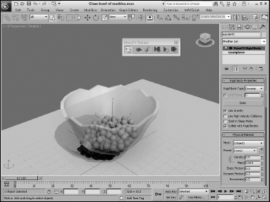
Tutorial: Filling a glass bowl
Imagine trying to animate a bunch of marbles falling into a glass bowl. If you were using keyframes, determining whether an object overlaps another would be difficult, but with this quick example you see the power of MassFX.
To animate marbles falling into a glass bowl, follow these steps:
- Open the Glass bowl of marbles.max file from the Chap 43 directory on the CD.
This file includes a glass bowl and several marbles positioned above its opening.
- Right-click the main toolbar, and select MassFX Toolbar. Then select all the marbles located above the bowl, and click the Set Selected as Dynamic Rigid Body button.
- Select the tabletop object, and click the Set Selected as Static Rigid Body button. This button is a flyout under the Set Selected as Dynamic Rigid Body button. Then click the Start Simulation button in the MassFX toolbar, and notice how the marbles all fall and spread out on the tabletop.
- Select the bowl object, and set it as a static object by repeating Step 3. This time, the marbles all fall into the bowl.
Figure 43.3 shows the bowl full of marbles positioned using MassFX.
FIGURE 43.3 MassFX can compute all the collisions between all these marbles.
Setting Object Properties
One of the first steps in creating with a simulation is defining the object properties. For example, a simple sphere object in Max could represent a bowling ball, an orange, or a tennis ball. Each of these objects responds very differently when being animated to drop on the floor.
Setting the object type
All objects involved in a MassFX simulation must be assigned one of three object types. The available object types are:
- Dynamic: These objects move when they collide with other objects. Dynamic objects also are affected by gravity.
- Kinematic: These objects impact other dynamic objects in the scene, but they don't move when they collide with dynamic objects. They can be animated and often provide the force to the simulation. Kinematic objects are not affected by gravity.
- Static: These objects have an infinite mass and don't move when they collide with other objects. They frequently are used for ground and walls. They also are not affected by gravity.
These object types are available as buttons in the MassFX toolbar. To specify an object as one of these types, simply select the object and click the object type button in the toolbar. Any object with a defined object type is automatically added to the simulation. Any scene object without an object type is simply ignored.
Kinematic objects can be animated using standard keyframe animation and then be changed to a dynamic object at a given frame using the Until Frame value located in the Rigid Body Properties rollout. This provides a way to add forces to the simulation such as a marble that is animated being shot at a group of marbles. Just before colliding, you can set the shot marble to become dynamic so it continues its motion and then interacts with the other marbles based on the physics.
When one of the object types is assigned to an object, it appears as a modifier in the Modifier Stack. If you remove this modifier, the object is removed from the simulation and returned to its original state.
When an object's type is defined as a dynamic, kinematic, or static, the system automatically assigns some rough physical properties based on the object's size in the scene. Static objects, for example, are given a large mass, which essentially makes them immovable, and small dynamic objects are given very small mass values.
The Rigid Body Properties rollout also includes options for disabling gravity and collisions and computing for high-velocity objects.
When dynamic objects are placed in the scene, it is often difficult to get them positioned exactly on top of one another. Actually, it is better to have a small gap between objects so they don't overlap. Overlapping objects will repel one another when the simulation first starts causing motion before you want it. Within the Rigid Body Properties rollout is the Start in Sleep Mode option that causes all dynamic objects to freeze in their initial positions until hit by another object. Enabling this option helps prevent the initial movement of stacked objects when the simulation starts due to gravity.
Regardless of the object type and its default values, you can set the actual physical properties for the selected object using the settings in the Physical Material rollout in the Command Panel when the object is selected. You can access these same properties in the Edit panel of the MassFX Tools dialog box, shown in Figure 43.4. You also can select and set the properties for multiple selected objects at the same time.
Tip
Although the Command Panel and the MassFX Tools dialog box have mostly the same settings, the MassFX Tools dialog box lets you set values for multiple selections at once.
FIGURE 43.4 The Edit panel of the MassFX Tools dialog box includes physical property values for the selected object.
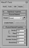
Density, mass, friction, and elasticity
Although many different physical properties are available, the MassFX system is mainly concerned with collisions between rigid body objects, which can be computed using a short list of physical properties including Density, Mass, Static Friction, Dynamic Friction, and Bounciness.
The Density property is the amount of mass per volume, so it's related to mass. The Mass property defines how heavy the object is. For example, a bowling ball has a higher mass value than a Ping-Pong ball, and a Ping-Pong ball is not as dense (or heavy) as a golf ball, even though they are roughly the same size.
Friction is the force of contact between two touching objects. It defines how resistant the object is to rolling or sliding along the floor. For example, when you slide an air-hockey puck over an air-hockey table, the friction is very low because of the jets of air, but moving a piece of sandpaper across a piece of wood has a very high value of friction that resists the movement.
Friction is actually defined by two properties. Static friction is the initial force required to start an object sliding across another, and dynamic friction is the amount of force required to keep the object sliding over the top of the other. Both of these properties are available in the MassFX system.
Note
A rigid body with a Mass value of 0 causes problems for all calculations, so the system automatically sets the Density or Mass value to 0.01 when you try to set it to 0.
Creating presets
If you've done some research and figured out the exact physical properties for a specific object, you can use the Create Preset button in the Physical Material rollout of the MassFX Tools dialog box to save and name the physical values for the selected object. All defined presets are populated in the drop-down list. This provides a great way to reuse values that you know are right. The eyedropper tool lets you quickly pick the properties from another object in the scene.
When a preset is used, all its properties are automatically locked, but you can unlock and change them using the Lock icon in the upper-left corner of the Physical Material Properties rollout of the MassFX Tools dialog box in the Edit panel.
Defining collision boundaries
Another common property that you can set pertains to how the object deals with collision detection. You can select the volume to use to determine when two objects collide with each other. If this sounds a bit funny because any collision volume that doesn't use the actual mesh would be inaccurate, then you need to realize that a complex simulation with lots of collisions of complex objects could take a long time to compute. If MassFX has only to compute collisions based on the object's bounding box instead of the actual mesh object, the simulation runs much more quickly, and the inaccuracies aren't even noticeable.
Before deciding on the collision boundary to use, you need to determine whether an object is convex or concave. A convex object is one that you can penetrate with a ray and cross its mesh boundary only twice. Concave objects require more than two crossings with an imaginary ray. In other words, concave meshes have surface areas that bend inward like a doughnut and convex meshes don't, like a normal sphere. Convex meshes are much easier to use when calculating collisions than concave meshes.
Using convex meshes
A convex object can use several of the options found in the Physical Meshes rollout, including Sphere, Box, Capsule, and Convex. Use the shape that best fits the mesh you are working with.
The properties for the mesh types are listed in the Physical Mesh Parameters rollout. When an object type is applied to an object, the Convex mesh type is applied by default, because it generally works for all objects. The Convex mesh type is created from a Geosphere object represented by 32 vertices. If you reduce the number of vertices—or switch to a Sphere, Box, or Capsule mesh type—you can speed up the simulation calculations.
Using the Inflation value, you can increase or decrease the size of the collision mesh. Additional settings are available in the Physical Mesh Parameters rollout for each type. For example, the Sphere mesh type has a Radius value and the Box mesh type has Length, Height, and Width values. If you make changes to the Convex mesh type that don't work, you can always regenerate the mesh using the Regenerate from Original button.
If the collision mesh shape is right, but its position is off, then you can choose the Mesh Transform subobject mode in the Modifier Stack and change the mesh's position and orientation.
Using concave meshes
If you have a concave object that you want to use in the simulation, you should first try to use a convex collision mesh if possible, but if you can't (such as with the bowl in the preceding example), the best option is the Composite mesh type. For example, a doughnut-shaped object bouncing in a scene could easily use a flat sphere shaped convex collision mesh because it isn't likely that a smaller object will go through the doughnut's center. However, if you are dealing with a basketball rim, then enabling a convex mesh won't work because objects will be going through the rim's center, so a concave collision mesh is required.
This Composite option lets you specify the number of vertices and several other settings and includes a Generate button to automatically create the collision mesh based on the object's geometry. Once generated, the number hulls and vertices included in the collision mesh are displayed. If these numbers are still too high, you can change the Max Vertices, Split Levels, or Size Difference values and try the Generate button again. Remember that more vertices means better accuracy in the simulation, but also more time to complete.
The Original option works well for concave objects that are set to static and won't move during the simulation. It uses the actual mesh as the collision mesh.
The Custom option lets you create a collision mesh based on selected piece of geometry in the scene. It includes buttons for picking the source object and extracting a mesh from the source object. The proxy mesh should be a low-resolution version of an object used here for collision detection.
Caution
Custom collision meshes are limited to objects with 256 vertices or less.
Setting initial motion
Every dynamic object has an initial motion setting that you can control to start the object in motion. This works whether gravity is enabled or disabled. The Initial Motion values are located in the Advanced rollout and can be set to an Absolute or Relative value. If a kinematic object is in motion when it is converted to a dynamic object using the Until Frame setting and it has an initial motion value, then the Absolute setting uses only the initial motion value and the Relative option adds the initial motion value to the existing keyframed motion that the object already has. The X, Y, and Z value denote a direction, and Speed sets how fast the object is moving. A setting for the initial spin of the object is available as well.
The Damping values are used to slow down the motion (Linear) and the rotation (Angular) of objects in motion with higher values causing the objects to rapidly decrease their speed.
Under the MassFX Rigid Body modifier that is applied to the selected object, you can select the Initial Velocity and Initial Spin subobject modes, and an arrow shows the current direction of the initial movement or spin. While either of these subobject modes is selected, you can use the Rotate tool to change them in the viewport. This is easier than having to enter values in the rollout.
The modifier also includes an option for changing the Center of Mass location and for moving and manipulating the collision mesh's transform.
Displaying interactions
The Display panel of the MassFX Tools dialog box has a number of options that you turn on and off to see the simulation properties. The Display Physical Meshes option shows the collision mesh for all objects or only for the selected objects if the Selected Objects Only option is enabled.
If you turn on the Enable Visualizer option, then a whole range of different properties are made visible as the simulation proceeds including arrows showing object speed, contact points between objects and collision meshes.
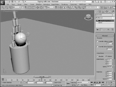
Tutorial: Knocking over milk cans
You can add motion to the simulation objects in two ways. One is to use the initial motion values in the Advanced rollout of the Edit panel of the MassFX Tools dialog box. The other is to set an object as a Kinematic object that is animated using standard keyframes and then switched to a Dynamic object at a given frame with the Until Frame option in the Rigid Body Properties rollout of the MassFX Tools dialog box.
To animate the milk can tipping carnival game, follow these steps:
- Open the Tipping milk cans.max file from the Chap 43 directory on the CD.
This file includes several milk cans positioned on a cylinder along with three balls.
- Right-click the main toolbar, and select MassFX Toolbar. Then select all the milk cans located above the cylinder, and click the Set Selected as Dynamic Rigid Body button. Then click the Display MassFX Tools Dialog button on the MassFX toolbar and in the Edit panel, set the Density value to 10 for all the milk cans.
- Select the cylinder and the floor objects, and click the Set Selected as Static Rigid Body button.
- Select the smallest ball object, and click the Set Selected as Dynamic Rigid Body button. Then open the Advanced rollout and set the X Initial Velocity value to −1 and the Speed value to 2500. Then click the Start Simulation button in the MassFX toolbar, and notice how the first ball falls a little short. Click the Reset Simulation button in the MassFX toolbar.
- Locate and click the Time Configuration button beneath the Play button at the bottom of the interface and in the Time Configuration dialog box, set the End Time to 300.
- Select the second ball object, and click the Set Selected as Kinematic Rigid Body button. Then enable the Until Frame option in the Rigid Body Properties rollout to 100. Then set the Density to 3, the X Initial Velocity value to −1 and the Speed value to 2500. Then click the Start Simulation button in the MassFX toolbar, and notice how the second ball knocks them all down.
Figure 43.5 shows the large ball striking the milk cans.
FIGURE 43.5 Kinematic objects can be made to start at a later frame.
Using Constraints
Constraints are ways to limit the amount of motion that an object can do. Using constraints can help control objects in the scene as they interact with other objects. Perhaps the simplest constraint isn't a constraint at all. If you set an object to be Static, it won't move.
Other constraints found in the MassFX toolbar include Rigid Constraint, Slide Constraint, Hinge Constraint, Twist Constraint, Universal Constraint, and Ball & Socket Constraint. To apply a constraint, you need two objects, and they both must be selected. The first object you select becomes the parent object and the second the child.
You can also select a single object and apply a constraint and then pick the parent object later using the button in the Modify panel.
After the constraint is selected, a helper object titled UConstraint is added to the scene, and you can drag out the helper object to show the range of the applied constraint. When the helper constraint object is selected, the parameters for the constraint are displayed in the Command Panel.
Constraints can be made Breakable, and you can set the Max Force and/or Torque required to break the constraint. Once a constraint is broken, it no longer has any affect on the simulation.
Within the Connection rollout, you can alter the objects that are used for the Parent and Child objects. Additional rollouts define the available translation, swing, twist, and spring properties for each type of constraint. For each, you can set the constraint to be Locked, Limited, or Free about each axis. If the Limited option is enabled, then you can set the limits using the values such as Limit Radius, Bounce, Spring, and Damping.
Although you can move the constraint helper to wherever it needs to be, it is often easier to define the constraint's location by positioning the object's pivot. In the Advanced rollout are buttons for moving the constraint helper to the parent or child's pivot location.
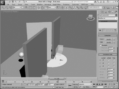
Tutorial: Opening a door
Each of the constraints enables different types of motion and some situations require multiple constraints, such as the hinge on a door.
To use constraints to restrict the motion of a door, follow these steps:
- Open the Door with a hinge.max file from the Chap 43 directory on the CD.
This file includes a simple door between two walls.
- Open the MassFX toolbar. Then select all the objects except the floor and click the Set Selected to Dynamic Rigid Body button. Select the floor object and set it to Static.
- Select the far wall object and then the door object and click the Create Hinge Constraint from the MassFX toolbar. Then drag in the viewport to set the constraint's size. Move the constraint so it is positioned at the point between the wall and the door and rotate it so it allows the door to swing away from the ball.
- Select both wall objects and choose the Create Rigid Constraint option from the MassFX toolbar. This prevents the walls from moving.
Caution
Static objects cannot be used as a parent or child for a constraint.
- Select the ball object and set its Density to 20, the X Initial Velocity value to −1, and the Speed value to 5000. This should be enough to give the door a good kick.
- Click the Start Simulation button in the MassFX toolbar.
Figure 43.6 shows the door flying open.
FIGURE 43.6 Using the hinge constraint controls the motion of this door.
Capturing the Simulation Motion as Keys
Once you're happy with the motion created by the simulation, you can capture the motion as keys using the Bake command. There is a Bake button in the Rigid Body Properties rollout of the Edit panel in the MassFX Tools dialog box. There are also several different bake options in the Tools panel including options to Bake All, Bake Selected, Unbake All, and Unbake Selected.
Once the motion is baked, the keys for each object in the simulation show up on the Track Bar and the animation can be manipulated and edited using the animation tools and the Track View.
The Tools panel also includes another helpful button. The Capture Transforms button causes the current state of the selected objects to be reset as its new initial position. If the Reset Simulation button is then used, this new initial position is used instead of the object's original location. This is great because it give you a chance to let the objects settle at the start simulation and then reset them in this location before starting the simulation.
Within the Utilities rollout of the Tools panel, the Explore Scene button opens the Scene Explorer where it shows all the objects included in the simulation and their respective simulation properties including SimType, SimMode, SimEnabled, and SimBaked. From this scene, you can quickly enable and disable multiple objects or change their object type.
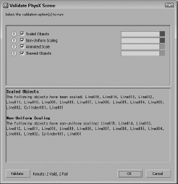
The Validate Scene button runs a quick check on the simulation looking for potential problems that might be encountered when the scene is exported, as shown in Figure 43.7. It looks for issues such as non-uniform scaling and skewed objects. The Export Scene button opens a dialog box where you can set the export options. Simulations can be exported to the XML, binary, or Collada formats.
FIGURE 43.7 Scenes can be validated before exporting to look for potential problems.
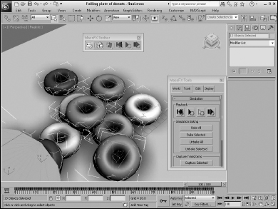
Tutorial: Dropping a plate of donuts
All the great books have an element of tragedy, so consider a policeman carrying a dozen donuts on a plate when he stumbles and drops the plate. Donuts everywhere, how tragic! This animation sequence would be difficult or at least time-consuming if it were not for MassFX.
To use MassFX to animate a falling plate of donuts, follow these steps:
- Open the Falling plate of donuts.max file from the Chap 43 directory on the CD.
This file includes a simple plate of donuts created from primitives.
- Open the MassFX toolbar. Then select all the donuts and the plate, and click the Set Selected to Dynamic Rigid Body button.
- Because the floor object is aligned to the ground plane, just make sure that the Use Ground Plane and the Gravity Enabled options are enabled in the World panel of the MassFX Tools dialog box.
- Click the Start Simulation button in the MassFX toolbar.
- After the simulation is complete and looks fine, click the Bake All button in the Tools panel of the MassFX Tools dialog box, and the keys for the animation are added to the Track Bar.
- When it completes, press the Play Animation button (or press the / key) to see the results.
Figure 43.8 shows the upturned plate of donuts. Oh, the tragedy, the horror, the creamy fillings.
FIGURE 43.8 Animating these falling donuts was easy with MassFX.
Summary
This chapter covered the basics of animating a dynamic simulation using MassFX. In this chapter, you accomplished the following:
- Understanding the principles of dynamics
- Accessing the MassFX tools
- Defining object types and properties
- Setting the collision mesh type
- Setting initial motion
- Working with constraints
- Baking animation keys
The next chapter covers the dynamic abilities of Max's hair and cloth systems.