
CHAPTER 11
Introducing Modifiers and Using the Modifier Stack
Using the Modifier Stack to manage modifiers
Learning to work with modifier gizmos
Exploring the Select modifiers
Deforming objects with the Parametric Deformer and FFD modifiers
Think for a moment of a woodshop with all its various (and expensive) tools and machines. Some tools, like a screwdriver or a sander, are simple, and others, like a lathe or router, are more complex, but they all change the wood (or models) in different ways. In some ways, you can think of modifiers as the tools and machines that work on 3D objects.
Each woodshop tool has different parameters that control how it works, such as how hard you turn the screwdriver or the coarseness of the sandpaper. Likewise, each modifier has parameters that you can set that determine how it affects the 3D object.
Modifiers can be used in a number of different ways to reshape objects, apply material mappings, deform an object's surface, and perform many other actions. Many different types of modifiers exist. This chapter introduces you to the concept of modifiers and explains the basics on how to use them. The chapter concludes by exploring two different categories of modifiers that are used to deform geometry objects: Parametric Deformers and Free Form Deformers (FFD).
Exploring the Modifier Stack
All modifiers applied to an object are listed together in a single location known as the Modifier Stack. This Stack is the manager for all modifiers applied to an object and can be found at the top of the Modify panel in the Command Panel. You can also use the Stack to apply and delete modifiers; cut, copy, and paste modifiers between objects; and reorder them.
Understanding Base Objects
The first entry in the Modifier Stack isn't a modifier at all; it is the Base Object. The Base Object is the original object type. The Base Object for a primitive is listed as its object type, such as Sphere or Torus. Editable meshes, polys, patches, and splines can also be Base Objects. NURBS Surfaces and NURBS Curves are also Base Objects.
You can also see the Base Objects using the Schematic View window if you enable the Base Objects option in the Display floater.
Applying modifiers
An object can have several modifiers applied to it. Modifiers can be applied using the Modifiers menu or by selecting the modifier from the Modifier List drop-down list located at the top of the Modify panel directly under the object name. Selecting a modifier in the Modifiers menu or from the Modifier List applies the modifier to the current selected object. Modifiers can be applied to multiple objects if several objects are selected.
Tip
You can quickly jump to a specific modifier in the Modifier List by pressing the first letter of the modifier that you want to select. For example, pressing the T key when the Modifier List is open immediately selects the Taper modifier.
Note
Some modifiers aren't available for some types of objects. For example, the Extrude and Lathe modifiers are enabled only when a spline or shape is selected.
Other Modifier Stack entities
Most modifiers are Object-Space modifiers, but another category called World-Space modifiers also exists. World-Space modifiers are similar to Object-Space modifiers, except they are applied using a global coordinate system instead of a coordinate system that is local to the object. More on World-Space modifiers is presented later in this chapter, but you should be aware that World-Space modifiers (identified with the initials WSM) appear at the top of the Modifier Stack and are applied to the object after all Object-Space modifiers.
In addition to World-Space modifiers, Space Warp bindings also appear at the top of the Modifier Stack.
Cross-Reference
Space Warps are covered in Chapter 42, “Using Space Warps.”
Using the Modifier Stack
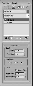
After a modifier is applied, its parameters appear in rollouts within the Command Panel. The Modifier Stack rollout, shown in Figure 11.1, lists the base object and all the modifiers that have been applied to an object. Any new modifiers applied to an object are placed at the top of the stack. By selecting a modifier from the list in the Modifier Stack, all the parameters for that specific modifier are displayed in rollouts.
FIGURE 11.1 The Modifier Stack rollout displays all modifiers applied to an object.
Tip
You can increase or decrease the size of the Modifier Stack by dragging the horizontal bar that appears beneath the Modifier Stack buttons.
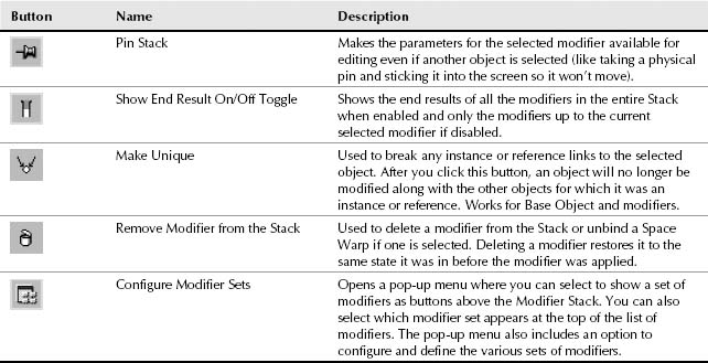
Beneath the Modifier Stack are five buttons that affect the selected modifier. They are as described in Table 11.1.
TABLE 11.1 Modifier Stack Buttons
Cross-Reference
For more information on configuring modifier sets, see Chapter 4, “Changing Interface Units and Setting Preferences.”
If you right-click on a modifier, a pop-up menu appears. This pop-up menu includes commands to rename the selected modifier, which you might want to do if the same modifier is applied to the same object multiple times. This pop-up menu also includes an option to delete the selected modifier among other commands.
Copying and pasting modifiers
The pop-up menu also includes options to cut, copy, paste, and paste instance modifiers. The Cut command deletes the modifier from the current object but makes it available for pasting onto other objects. The Copy command retains the modifier for the current object and makes it available to paste onto another object. After you use the Cut or Copy command, you can use the Paste command to apply the modifier to another object. The Paste Instance command retains a link between the original modifier and the instanced modifier, so that any changes to either modifier affect the other instances.
You can also apply modifiers for the current object onto other objects by dragging the modifier from the Modifier Stack and dropping it on the other object in a viewport. Holding down the Ctrl key while dropping a modifier onto an object in a viewport applies the modifier as an instance (like the Paste Instanced command). Holding down the Shift key while dragging and dropping a modifier on an object in the viewport removes the modifier from the current object and applies it to the object on which it is dropped (like the Cut and Paste commands).
You can also cut, copy, and paste modifiers using the Schematic View window. See Chapter 25, “Building Complex Scenes with Containers, XRefs, and the Schematic View,” for more details.
Using instanced modifiers
When you apply a single modifier to several objects at the same time, the modifier shows up in the Modifier Stack for each object. These are instanced modifiers that maintain a connection to each other. If one of these instanced modifiers is changed, the change is propagated to all other instances. This feature is very helpful for modifying large groups of objects.
When a modifier is copied between different objects, you can select to make the copy an instance.
To see all the objects that are linked to a particular modifier, select an object in the viewport and choose Views ![]() Show Dependencies. All objects with instanced modifiers that are connected to the current selection appear in bright pink. At any time, you can break the link between a particular instanced modifier and the rest of the objects using the Make Unique button in the Modifier Stack rollout.
Show Dependencies. All objects with instanced modifiers that are connected to the current selection appear in bright pink. At any time, you can break the link between a particular instanced modifier and the rest of the objects using the Make Unique button in the Modifier Stack rollout.
Identifying instances and references in the Modifier Stack
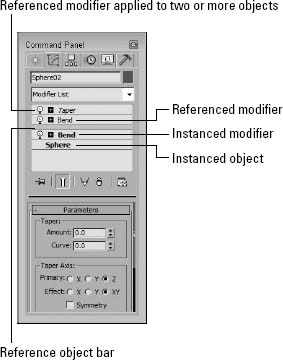
If you look closely at the Modifier Stack, you will notice that it includes some visual clues that help you identify instances and references. Regular object and modifier copies appear in normal text, but instances appear in bold. This applies to both objects and modifiers. If a modifier is applied to two or more objects, then it appears in italic.
Referenced objects and modifiers can be identified by a Reference Object Bar that splits the Modifier Stack into two categories—ones that are unique to the referenced object (above the bar) and ones that are shared with the other references (below the bar).
Figure 11.2 shows each of these cases in the Modifier Stack.
Disabling and removing modifiers
Clicking the light bulb icon to the left of the modifier name toggles the modifier on and off. The right-click pop-up menu also offers options to turn the modifier off in the viewport or off for the renderer.
To remove a modifier from the Modifier Stack, just select the modifier and press the Remove Modifier button below the stack. This button removes the selected modifier only. You can select multiple modifiers at once by holding down the Ctrl key while clicking individually on the modifiers or by holding down the Shift key and clicking on the first and last modifiers in a range.
Reordering the Stack
Modifiers are listed in the Modifier Stack with the first applied ones on the bottom and the newest applied ones on the top. The Stack order is important and can change the appearance of the object. Max applies the modifiers starting with the lowest one in the Stack first and the topmost modifier last. You can change the order of the modifiers in the Stack by selecting a modifier and dragging it above or below the other modifiers. You cannot drag it below the object type or above any World-Space modifiers or Space Warp bindings.
FIGURE 11.2 The Modifier Stack changes the text style to identify instances and references.
Tutorial: Creating a molecular chain
Whether you're working with DNA splices or creating an animation to show how molecular chains are formed, you can use the Lattice and Twist modifiers to quickly create a molecular chain. Using these chains shows how reordering the Modifier Stack can change the outcome.
To create a molecular chain using modifiers, follow these steps:
- Select Create
 Standard Primitives Plane, and drag in the Top viewport to create a Plane object. Set its Length to 300, its Width to 60, its Length Segments to 11, and its Width Segments to 1.
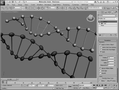
 - With the Plane object selected, select Modifiers Parametric Deformers Lattice to apply the Lattice modifier. Enable the Apply to Entire Object option. Then set the Struts Radius value to 1.0 with 12 sides and the Joints Base Type to Icosa with a Radius of 6.0 and a Segments value of 6.
- Select Modifiers Parametric Deformers Twist, and set the Twist Angle to 360 about the Y-axis.
- Notice that the Sphere objects have been twisted along with the Plane object. You can fix this by switching the modifier order in the Modifier Stack. Select the Lattice modifier, and drag and drop it above the Twist modifier in the stack.
This step corrects the elongated spheres.
Figure 11.3 shows the corrected molecular chain.
FIGURE 11.3 Changing the order of the modifiers in the Stack can affect the end result.
Holding and fetching a scene
Before going any further, you need to know about an important feature in Max that allows you to set a stopping point for the current scene. The Edit ![]() Hold command saves the scene into a temporary buffer for easy recovery. After a scene is set with the Hold command (Ctrl+H), you can bring it back instantly with the Edit
Hold command saves the scene into a temporary buffer for easy recovery. After a scene is set with the Hold command (Ctrl+H), you can bring it back instantly with the Edit ![]() Fetch command (Alt+Ctrl+F). These commands provide a quick way to backtrack on modifications to a scene or project without having to save and reload the project. If you use these commands before applying or deleting modifiers, you can avoid some potential headaches.
Fetch command (Alt+Ctrl+F). These commands provide a quick way to backtrack on modifications to a scene or project without having to save and reload the project. If you use these commands before applying or deleting modifiers, you can avoid some potential headaches.
Tip
Along with saving your file often, using the Hold command before applying any complex modifier to an object is a good idea.
Collapsing the Stack
Collapsing the Stack removes all its modifiers by permanently applying them to the object. It also resets the modification history to a baseline. All the individual modifiers in the Stack are combined into one single modification. This feature eliminates the ability to change any modifier parameters, but it simplifies the object. The right-click pop-up menu offers options to Collapse To and Collapse All. You can collapse the entire Stack with the Collapse All command, or you can collapse to the current selected modifier with the Collapse To command. Collapsed objects typically become Editable Mesh objects.
Another huge advantage of collapsing the Modifier Stack is that it conserves memory and results in smaller file sizes, which makes larger scenes load much quicker. Collapsing the Modifier Stack also speeds up rendering because Max doesn't need to calculate the stack results before rendering.
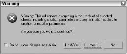
When you apply a collapse command, a warning dialog box appears, shown in Figure 11.4, notifying you that this action will delete all the creation parameters. Click Yes to continue with the collapse.
Note
In addition to the Yes and No buttons, the warning dialog box includes a Hold/Yes button. This button saves the current state of the object to the Hold buffer and then applies the Collapse All function. If you have any problems, you can retrieve the object's previous state before the collapse was applied by choosing Edit ![]() Fetch (Alt+Ctrl+F).
Fetch (Alt+Ctrl+F).
FIGURE 11.4 Because the Collapse operation cannot be undone, this warning dialog box offers a chance to Hold the scene.
Using the Collapse utility
You can also use the Collapse utility found on the Utility panel to collapse the Modifier Stack. This utility enables you to collapse an object or several objects to a Modifier Stack Result or to a Mesh object. Collapsing to a Modifier Stack Result doesn't necessarily produce a mesh but collapses the object to its base object state, which is displayed at the bottom of the Stack hierarchy. Depending on the Stack, this could result in a mesh, patch, spline, or other object type. You can also collapse to a Single Object or to Multiple Objects.
If the Mesh and Single Object options are selected, you can also select to perform a Boolean operation. The Boolean operations are available if you are collapsing several overlapping objects into one. The options are Union (which combines geometries together), Intersection (which combines only the overlapping geometries), and Subtraction (which subtracts one geometry from another).
Cross-Reference
Boolean operations can also be performed using the Boolean compound object. See Chapter 27, “Working with Compound Objects,” for details on this object type.
If multiple objects are selected, then a Boolean Intersection results in only the sections of the objects that are intersected by all objects; if no objects overlap, all objects disappear.
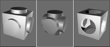
If you use the Boolean Subtraction option, you can specify which object is the base object from which the other objects are subtracted. To do so, select that object first and then select the other objects by holding down the Ctrl key and clicking them. Figure 11.5 shows an example of each of the Boolean operations.
FIGURE 11.5 Using the Collapse utility, you can select the following Boolean operations (shown from left to right): Union, Intersection, and Subtraction.
Using gizmo subobjects
As you've worked with modifiers, you've probably noticed the orange wireframe box that surrounds the object in the viewports when you apply the modifier. These boxes are called modifier gizmos, and they provide a visual control for how the modifier changes the geometry. If you want, you can work directly with these gizmos to affect the modifier.
Clicking the plus sign to the left of the modifier name reveals any subobjects associated with the modifier. To select the modifier subobjects, simply click the subobject name. The subobject name is highlighted in yellow when selected. Many modifiers create gizmo subobjects. Gizmos have an icon usually in the shape of a box that can be transformed and controlled like regular objects using the transformation buttons on the main toolbar. Another common modifier subobject is Center, which controls the point about which the gizmo is transformed.
Tutorial: Squeezing a plastic bottle
To get a feel for how the modifier gizmo and its center affect an object, this tutorial applies the Squeeze modifier to a plastic bottle; by moving its center, you can change the shape of the object.
To change a modifier's characteristics by moving its center, follow these steps:
- Open the Plastic bottle.max file from the Chap 11 directory on the CD.
This file includes a plastic squirt bottle with all the parts attached into a single mesh object.
- With the bottle selected, choose the Modifiers Parametric Deformers Squeeze menu command to apply the Squeeze modifier to the bottle. Set the Radial Squeeze Amount value to 1.
- In the Modifier Stack, click the plus sign to the left of the Squeeze modifier to see the modifier's subobjects. Select the Center subobject.
The selected subobject is highlighted in yellow.
- Click the Select and Move (W) button on the main toolbar, and drag the center point in the Perspective viewport upward.
Notice how the bottle's shape changes.
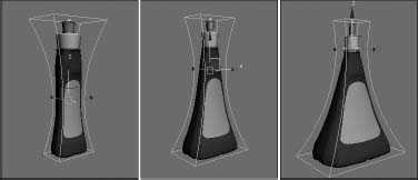
Figure 11.6 shows several different bottle shapes created by moving the modifier's center point.
FIGURE 11.6 By changing the modifier's center point, the bottle's shape changes.
Modifying subobjects
In addition to being applied to complete objects, modifiers can also be applied and used to modify subobjects. A subobject is defined as a collection of object parts, such as vertices, edges, faces, or elements.
Cross-Reference
To learn more about applying modifiers to subobject selections, see Chapter 10, “Accessing Subobjects and Using Modeling Helpers.”
To work in subobject selection mode, click the plus sign to the left of the object name to see the subobjects. Several modifiers, including Mesh Select, Spline Select, and Volume Select, can select subobject areas for passing these selections up to the next modifier in the Stack. For example, you can use the Mesh Select modifier to select several faces on the front of a sphere and then apply the Face Extrude modifier to extrude just those faces.
Topology dependency
When you attempt to modify the parameters of a Base Object that has a modifier applied, you sometimes get a warning dialog box that tells you that the modifier depends on topology that may change. Max is telling you that the surface of the object with that particular modifier is dependent on the subobjects that are selected and if you change the underlying subobjects, you may change the resulting topology. For example, the CrossSection and Surface modifiers build the surface using a set of splines, but if you change the original spline, you can destroy the resulting surfaced object. You can eliminate this problem by collapsing the Modifier Stack.
You can disable the warning by selecting the “Do not show this message again” option on the dialog box or by opening the Preference Settings dialog box and turning off the Display Topology-Dependence Warning option in the General panel of the Preference Settings dialog box. Disabling the warning does not make the potential problem go away; it only prevents the warning dialog box from appearing.
Exploring Modifier Types
To keep all the various modifiers organized, Max has grouped them into several distinct modifier sets. The modifier sets, as listed in the Modifier menu, include those listed in Table 11.2.
TABLE 11.2 Modifiers Menu Items
You can find roughly these same sets if you click the Configure Modifier Sets button in the Modifier Stack. Within this list is a single selected set. The selected set is marked with an arrow to the left of its name. The modifiers contained within the selected set appear at the very top of the Modifier List.
Cross-Reference
Covering all the modifiers together would result in a very long chapter. Instead, I decided to cover most of the modifiers in their respective chapters. For example, you can learn about the Mesh Editing modifiers in Chapter 26, “Deforming Surfaces and Using the Mesh Modifiers”; animation modifiers in Chapter 35, “Using Animation Layers, Modifiers, and Complex Controllers”; the UV Coordinates modifiers in Chapter 33, “Unwrapping UVs and Mapping Textures”; and so on. This chapter covers the Selection modifiers, Parametric Deformers, and FFD modifiers.
Object-Space versus World-Space modifiers
If you view the modifiers listed in the Modifier List, they are divided into two categories: Object-Space and World-Space modifiers (except for the selected set of modifiers that appear at the very top for quick access). Object-Space modifiers are more numerous than World-Space modifiers. For most World-Space modifiers, there is also an Object-Space version. World-Space modifiers are all identified with the abbreviation WSM, which appears next to the modifier's name.
Object-Space modifiers are modifiers that are applied to individual objects and that use the object's Local Coordinate System, so as the object is moved, the modifier goes with it.
World-Space modifiers are based on World-Space coordinates instead of on an object's Local Coordinate System, so after a World-Space modifier is applied, it stays put, no matter where the object with which it is associated moves.
Another key difference is that World-Space modifiers appear above all Object-Space modifiers in the Modifier Stack, so they affect the object only after all the other modifiers are applied.
Cross-Reference
All Space Warps are also applied using World-Space coordinates, so they also have the WSM letters next to their name. You can get more information on Space Warps in Chapter 42, “Using Space Warps.”
Selection modifiers
The first modifiers available in the Modifiers menu are the Selection modifiers. You can use these modifiers to select subobjects for the various object types. You can then apply other modifiers to these subobject selections. Any modifiers that appear above a Selection modifier in the Modifier Stack are applied to the subobject selection.
Selection modifiers are available for every modeling type, including Mesh Select, Poly Select, Patch Select, Spline Select, Volume Select, FFD Select, and Select by Channel. There is also a Surface Select in the NURBS Editing category. You can apply the Mesh Select, Poly Select, Patch Select, and Volume Select modifiers to any 3D object, but you can apply the Spline Select modifier only to spline and shape objects, the FFD Select modifier only to the FFD Space Warps objects, and the NURBS Surface Select modifier (found in the NURBS Editing submenu) only to NURBS objects. Any modifiers that appear above one of these Selection modifiers in the Modifier Stack are applied only to the selected subobjects.
Cross-Reference
Each of the Selection modifiers is covered for the various modeling types in its respective chapter. For example, to learn about the Patch Select modifier, see Bonus Chapter 5 on the CD, “Working with NURBS.”
When a Selection modifier is applied to an object, the transform buttons on the main toolbar become inactive. If you want to transform the subobject selection, you can do so with the XForm modifier.
Volume Select modifier
Among the Selection modifiers, the Volume Select modifier is unique. It selects subobjects based on the area defined by the modifier's gizmo. The Volume Select modifier selects all subobjects within the volume from a single object or from multiple objects. One of the benefits of using this modifier is that the subobjects within the volume can change as the object is moved during an animation sequence. It also can work with several objects at once.
In the Parameters rollout for the Volume Select modifier, you can specify whether subobjects selected within a given volume should be Object, Vertex, or Face subobjects. Any new selection can Replace, be Added to, or be Subtracted from the current selection. You can use the Invert option to select the subobjects outside of the current volume. You can also choose either a Window or Crossing Selection Type.
The actual shape of the gizmo can be a Box, Sphere, Cylinder, or Mesh Object. To use a Mesh Object, click the button beneath the Mesh Object option and then click the object to use in a viewport. In addition to selecting by a gizmo-defined volume, you can also select subobjects based on certain surface characteristics, such as Material IDs, Smoothing Groups, or a Texture Map including Mapping Channel or Vertex Color. This makes it possible to quickly select all vertices that have a Vertex Color assigned to them.
The Alignment options can Fit or Center the gizmo on the current subobject selection. The Reset button moves the gizmo to its original position and orientation, which typically is the bounding box of the object. The Auto Fit option automatically changes the size and orientation of the gizmo as the object it encompasses changes.
Note
The Volume Select modifier also includes a Soft Selection rollout. Soft Selection lets you select adjacent subobjects to a lesser extent. The result is a smoother selection over a broader surface area. The Soft Selection options are explained in Chapter 10, “Accessing Subobjects and Using Modeling Helpers.”
Tutorial: Applying damage to a car
In this tutorial, you use the Volume Select modifier to select the front corner of a car and then apply Noise and XForm modifiers to make the corner look like it's been damaged in a collision.
To use modifiers to make a section of a car appear damaged, follow these steps:
- Open the Damaged car.max file from the Chap 11 directory on the CD.
This file includes a car model created by Viewpoint Datalabs.
- With the front end of the car selected, choose the Modifiers Selection Modifiers Volume Select menu command.
This command applies the Volume Select modifier to the group.
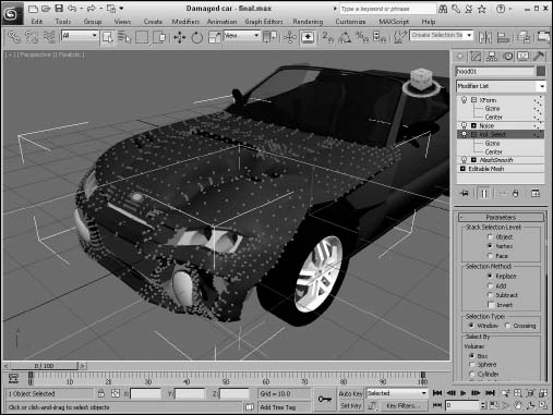
- In the Modifier Stack, click the plus icon to the left of the modifier name and select the Gizmo subobject. Move the gizmo in the Top viewport so only the front corner of the car is selected. In the Parameters rollout, select the Vertex option.
- Choose the Modifiers Parametric Deformers Noise menu command to apply the Noise modifier to the selected volume. In the Parameters rollout, enable the Fractal option and set the X, Y, and Z Strength values to 30.
- Choose Modifiers Parametric Deformers XForm to apply the XForm modifier, and use its gizmo to push the selected area up and to the left in the Top viewport. This step makes the section look dented.
Figure 11.7 shows the resulting damaged car. Notice that the rest of the object is fine and only the selected volume area is damaged.
Cross-Reference
You can see another example of how a Selection modifier can be used to select and apply a modifier to a subobject selection in Chapter 10, “Accessing Subobjects and Using Modeling Helpers.”
FIGURE 11.7 The Noise and XForm modifiers are applied to just the subobject selection.
Parametric Deformer modifiers
Perhaps the most representative group of modifiers are the Parametric Deformers. These modifiers affect the geometry of objects by pulling, pushing, and stretching them. They all can be applied to any of the modeling types, including primitive objects.
Note
In the upcoming examples, you might start to get sick of seeing the hammer model used over and over, but using the same model enables you to more easily compare the effects of the various modifiers, and it's more interesting to look at than a simple box.
Affect Region modifier
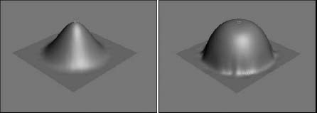
The Affect Region modifier can cause a local surface region to bubble up or be indented. Affect Region parameters include Falloff, Pinch, and Bubble values. The Falloff value sets the size of the affected area. The Pinch value makes the region tall and thin, and the Bubble value rounds the affected region.
You also can select the Ignore Back Facing option. Figure 11.8 shows the Affect Region modifier applied to a Quad Patch with a Falloff value of 80 on the left and with a Bubble value of 1.0 on the right. The height and direction of the region are determined by the position of the modifier gizmo, which is a line connected by two points.
Note
The Affect Region modifier accomplishes the same effect as the Soft Selection feature, but Affect Region applies the effect as a modifier, making it easier to discard.
FIGURE 11.8 The Affect Region modifier can raise or lower the surface region of an object.
Bend modifier
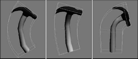
The Bend modifier can bend an object along any axis. Bend parameters include the Bend Angle and Direction, Bend Axis, and Limits. The Bend Angle defines the bend in the vertical direction, and the Direction value defines the bend in the horizontal direction.
Limit settings are the boundaries beyond which the modifier has no effect. You can set Upper and Lower Limits relative to the object's center, which is placed at the object's pivot point. Limits are useful if you want the modifier applied to only one half of the object. The Upper and Lower Limits are visible as a simple plane on the modifier gizmo. For example, if you want to bend a tall cylinder object and have the top half remain straight, you can simply set an Upper Limit for the cylinder at the location where you want it to stay linear.
Note
Several modifiers have the option to impose limits on the modifier, including Upper and Lower Limit values.
The hammer in Figure 11.9 shows several bending options. The left hammer shows a Bend value of 75 degrees around the Z-axis, the middle hammer also has a Direction value of 60, and the right hammer has an Upper Limit of 8.
FIGURE 11.9 The Bend modifier can bend objects about any axis.
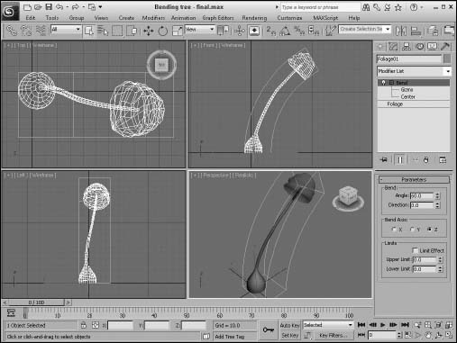
Tutorial: Bending a tree
If you have a tree model that you want to bend as if the wind were blowing, you can apply the Bend modifier. The tree then bends about its Pivot Point. Luckily, all the trees and plants found in the AEC Objects category have their Pivot Points set about their base, so bending a tree is really easy.
To bend a tree using the Bend modifier, follow these steps:
- Select the Create AEC Objects Foliage menu command to access the available trees. Select a long, thin tree like the Yucca, and click in the Top viewport to add it to the scene.
- With the tree selected, select the Modifiers Parametric Deformers Bend menu command to apply the Bend modifier to the tree.
- In the Parameters rollout found in the Modify panel, set the Bend Axis to Z and the Bend Angle to 60.
The tree bends as desired.
Figure 11.10 shows the bending Yucca plant. To animate this tree bending back and forth, just set keys for the Angle parameter.
Displace modifier
The Displace modifier offers two unique sets of features. It can alter an object's geometry by displacing elements using a gizmo, or it can change the object's surface using a grayscale bitmap image. The Displace gizmo can have one of four different shapes: Planar, Cylindrical, Spherical, or Shrink Wrap. This gizmo can be placed exterior to an object or inside an object to push it from the inside.
Caution
In order for the Displace modifier to work, the surface requires a dense mesh, which can lead to very high polygon counts.
FIGURE 11.10 The Bend modifier can be used to bend trees.
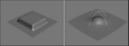
The Displace modifier parameters include Strength and Decay values. You can also specify the dimensions of the gizmo. A cylindrical-shaped gizmo can be capped or uncapped. The alignment parameters let you align the gizmo to the X-axis, Y-axis, or Z-axis, or you can align it to the current view. The rest of the parameters deal with displacing the surface using a bitmap image. Figure 11.11 shows a Quad Patch with the Plane-shaped gizmo applied with a Strength value of 25. To the right is a Quad Patch with the Sphere-shaped gizmo.
FIGURE 11.11 You can use the Displace modifier's gizmo as a modeling tool to change the surface of an object.
The Displace modifier can also alter an object's geometry using a grayscale bitmap image. This is similar to a Displacement map, which is covered in Chapter 17, “Adding Material Details with Maps.” In many ways, the Displace gizmo works like the Conform compound object. You can learn about the Conform compound object in Chapter 27, “Working with Compound Objects.”
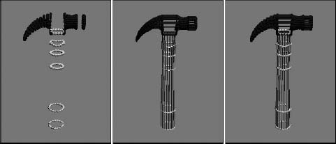
Lattice modifier
The Lattice modifier changes an object into a lattice by creating struts where all the edges are located or by replacing each joint with an object. The Lattice modifier considers all edges as struts and all vertices as joints.
parameters for this modifier include several options to determine how to apply the effect. These options include Apply to Entire Object, to Joints Only, to Struts Only, or Both (Struts and Joints). If the Apply to Entire Object option isn't selected, then the modifier is applied to the current subobject.
For struts, you can specify Radius, Segments, Sides, and Material ID values. You can also specify to Ignore Hidden Edges, to create End Caps, and to Smooth the Struts.
For joints, you can select Tetra, Octa, or Icosa types with Radius, Segments, and Material ID values. There are also controls for Mapping Coordinates.
Note
Although the joints settings enable you to select only one of three different types, you can use the Scatter compound object to place any type of object instead of the three defaults. To do this, apply the Lattice modifier and then select the Distribute Using All Vertices option in the Scatter Objects rollout.
Figure 11.12 shows the effect of the Lattice modifier. The left hammer has only joints applied, the middle hammer has only struts applied, and the right hammer has both applied.
FIGURE 11.12 The Lattice modifier divides an object into struts, joints, or both.
Mirror modifier
You can use the Mirror modifier to create a mirrored copy of an object or subobject. The Parameters rollout lets you pick a mirror axis or plane and an Offset value. The Copy option creates a copy of the mirrored object and retains the original selection.
The Mirror modifier works the same as the Mirror command found in the Tools menu, but the modifier is handy if you want to be able to quickly discard the mirroring changes.
Noise modifier
The Noise modifier randomly varies the position of object vertices in the direction of the selected axes. Noise parameters include Seed and Scale values, a Fractal option with Roughness and Iterations settings, Strength about each axis, and Animation settings.
The Seed value sets the randomness of the noise. If two identical objects have the same settings and the same Seed value, they look exactly the same even though a random noise has been applied to them. If you alter the Seed value for one of them, then they will look dramatically different.
The Scale value determines the size of the position changes, so larger Scale values result in a smoother, less rough shape. The Fractal option enables fractal iterations, which result in more jagged surfaces. If Fractal is enabled, Roughness and Iterations become active. The Roughness value sets the amount of variation, and the Iterations value defines the number of times to complete the fractal computations. More iterations yield a wilder or chaotic surface but require more computation time.
If the Animate Noise option is selected, the vertices positions will modulate for the duration of frames. The Frequency value determines how quickly the object's noise changes, and the Phase setting determines where the noise wave starts and ends.
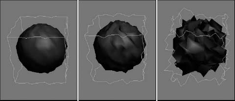
Figure 11.13 shows the Noise modifier applied to several sphere objects. These spheres make the Noise modifier easier to see than on the hammer object. The left sphere has Seed, Scale, and Strength values along all three axes set to 1.0, the middle sphere has increased the Strength values to 2.0, and the right sphere has the Fractal option enabled with a Roughness value of 1.0 and an Iterations value of 6.0.
FIGURE 11.13 The Noise modifier can apply a smooth or wild look to your objects.
Cross-Reference
The Physique modifier is one of the original Character Studio tools. Although both modifiers still exist, the Skin modifier is preferred. It is covered in Chapter 40, “Skinning Characters.”
Push modifier
The Push modifier pushes an object's vertices inward or outward as if they were being filled with air. The Push modifier also has one parameter: the Push value. This value is the distance to move with respect to the object's center.
The positive Push value pushes the vertices outward away from the center, and a negative Push value pulls the vertices in toward the center. The Push modifier can increase the size of characters or make an object thinner by pulling its vertices in. Figure 11.14 shows the hammer pushed with 0.05, 0.1, and 0.15 values.
FIGURE 11.14 The Push modifier can increase the volume of an object.
Preserve modifier
The Preserve modifier works to maintain Edge Lengths, Face Angles, and Volume as an object is deformed and edited. Before an object is modified, make an additional copy. Then edit one of the copies. To apply the Preserve modifier, click the Pick Original button; then click the unmodified object, and finally click the modified object. The object is modified to preserve the Edge Lengths, Face Angles, and Volume as defined in the Weight values. This helps prevent the topology of the modified object from becoming too irregular.
Note
In order for the Preserve modifier to keep objects and modifiers in check, it must be placed above the objects and modifiers it is watching.
The Iterations option determines the number of times the process is applied. You can also specify to apply to the Whole Mesh, to Selected Vertices Only, or to an Inverted Selection.
Relax modifier
The Relax modifier tends to smooth the overall geometry by separating vertices that lie closer than an average distance. Parameters include a Relax Value, which is the percentage of the distance that the vertices move. Values can range between 1.0 and –1.0. A value of 0 has no effect on the object. Negative values have the opposite effect, causing an object to become tighter and more distorted.
As you model, it is common for meshes to have sections that are too tight, which are dense locations in the mesh where a large concentration of vertices are close together. The Relax modifier can be used to cause the areas that are too tight to be relaxed.
The Iterations value determines how many times this calculation is computed. The Keep Boundary Points Fixed option removes any points that are next to an open hole. Save Outer Corners maintains the vertex position of corners of an object.
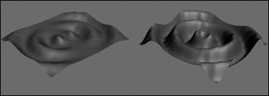
Ripple modifier
The Ripple modifier creates ripples across the surface of an object. This modifier is best used on a single object; if several objects need a ripple effect, use the Ripple Space Warp. The ripple is applied via a gizmo that you can control. Parameters for this modifier include two Amplitude values and values for the Wave Length, Phase, and Decay of the ripple.
The two amplitude values cause an increase in the height of the ripples opposite one another. Figure 11.15 shows the Ripple modifier applied to a simple Quad Patch with values of 10 for Amplitude 1 and a Wave Length value of 50. The right Quad Patch also has an Amplitude 2 value of 20.
FIGURE 11.15 The Ripple modifier can make small waves appear over the surface of an object.
Shell modifier
When a mesh subobject is deleted, it leaves a hole in the surface that allows the inside of the object to be seen. This inside section doesn't have normals pointing the right direction, so the object appears blank unless the Force 2-Sided option in the Viewport Configuration dialog box is selected. The Shell modifier makes an object into a shell with a surface on the inside and outside of the object.
For the Shell modifier, you can specify Inner and Outer Amount values. This is the distance from the original position that the inner or outer surfaces are moved. These values together determine how thick the shell is. The Bevel Edges and Bevel Spline options let you bevel the edges of the shell. By clicking on the Bevel Spline button, you can select a spline to define the bevel shape.
For each Material ID, you can use the Material ID for the inner section or the outer section. The Auto Smooth Edge lets you smooth the edge for all edges that are within the Angle threshold. The edges can also be mapped using the Edge Mapping options. The options include Copy, None, Strip, and Interpolate. The Copy option uses the same mapping as the original face, None assigns new mapping coordinates, Strip maps the edges as one complete strip, and Interpolate interpolates the mapping between the inner and outer mapping.
The last options make selecting the edges, the inner faces, or the outer faces easy. The Straighten Corners option moves the vertices so the edges are straight.
Tutorial: Making a character from a sphere
Creating a little game character from a sphere is a good example of how the Shell modifier can be used.
To use the Shell modifier to create a character, follow these steps:
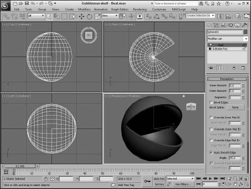
- Open the Gobbleman shell.max file from the Chap 11 directory on the CD.
This file includes a simple sphere object that has had several faces deleted.
- With the sphere object selected, select Modifiers Parametric Deformers Shell to apply the Shell modifier. Set the Outer Amount to 5.0.
This makes the hollow sphere into a thin shell. Notice that the lighting inside the sphere is now correct.
Figure 11.16 shows the resulting shell.
FIGURE 11.16 The Shell modifier can add an inside to hollow objects.
Slice modifier
You can use the Slice modifier to divide an object into two separate objects. Applying the Slice modifier creates a Slice gizmo. This gizmo looks like a simple plane and can be transformed and positioned to define the slice location. To transform the gizmo, you need to select it from the Stack hierarchy.
Note
You can use the Slice modifier to make objects slowly disappear a layer at a time.
The Slice parameters include four slice type options. Refine Mesh simply adds new vertices and edges where the gizmo intersects the object. The Split Mesh option creates two separate objects. The Remove Top and Remove Bottom options delete all faces and vertices above or below the gizmo intersection plane.
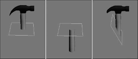
Using Triangular or Polygonal faces, you can also specify whether the faces are divided. Figure 11.17 shows the top and bottom halves of a hammer object. The right hammer is sliced at an angle.
FIGURE 11.17 The Slice modifier can cut objects into two separate pieces.
Note
Editable meshes also have a Slice tool that can produce similar results. The difference is that the Slice modifier can work on any type of object, not only on meshes.
Skew modifier
The Skew modifier changes the tilt of an object by moving its top portion while keeping the bottom half fixed. Skew parameters include Amount and Direction values, a Skew Axis, and Limits. Figure 11.18 shows the hammer on the left with a Skew value of 2.0, in the middle with a Skew value of 5, and on the right with an Upper Limit of 8.
FIGURE 11.18 You can use the Skew modifier to tilt objects.
Stretch modifier
The Stretch modifier moves one axis in one direction while moving the other axes in the opposite direction, like pushing in on opposite sides of a balloon. Stretch parameters include Stretch and Amplify values, a Stretch Axis, and Limits.
The Stretch value equates the distance the object is pulled, and the Amplify value is a multiplier for the Stretch value. Positive values multiply the effect, and negative values reduce the stretch effect.
Figure 11.19 shows a Stretch value of 0.2 about the Z-axis applied to the hammer; the middle hammer also has an Amplify value of 2.0; and the right hammer has an Upper Limit value of 8.
FIGURE 11.19 The Stretch modifier pulls along one axis while pushing the other two.
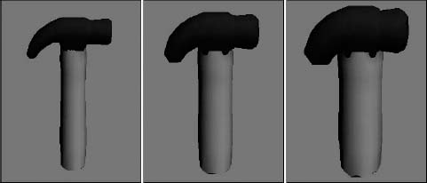
Spherify modifier
The Spherify modifier distorts an object into a spherical shape. The single Spherify parameter is the percent of the effect to apply. Figure 11.20 shows the hammer with Spherify values of 10, 20, and 30 percent.
The Spherify modifier is different from the Push modifier. Although they both are applied to the entire object, the Push modifier forces all vertices continuously outward, and the Spherify modifier uses a sphere shape as a limiting boundary. The visible difference is that the Spherify modifier creates a bulging effect.
FIGURE 11.20 The Spherify modifier pushes all vertices outward like a sphere.
Tutorial: Making a fat crocodile
A good way to use the Spherify modifier is to add bulges to an object. For example, in this tutorial, you make a plump crocodile even fatter by applying the Spherify modifier.
To fatten up a crocodile character with the Spherify modifier, follow these steps:
- Open the Fat crocodile.max file from the Chap 11 directory on the CD.
This file includes a crocodile model created by Viewpoint Datalabs.
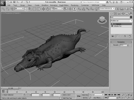
- With the crocodile selected, select the Modifiers Parametric Deformers Spherify menu command to apply the Spherify modifier to the crocodile.
The bulge appears around the object's pivot point.
- In the Parameters rollout, set the Percent value to 15.
Figure 11.21 shows the plump crocodile.
Note
The drawback of the Spherify modifier is that you have no control over its placement because there isn't a gizmo that you can position. One way around this problem is to use the Volume Select modifier to select a specific volume that is passed up the stack to the Spherify modifier.
FIGURE 11.21 The Spherify modifier can fatten up a crocodile.
Squeeze modifier
The Squeeze modifier takes the points close to one axis and moves them away from the center of the object while it moves other points toward the center to create a bulging effect. Squeeze parameters include Amount and Curve values for Axial Bulge and Radial Squeeze, and Limits and Effect Balance settings.
The Effect Balance settings include a Bias value, which changes the object between the maximum Axial Bulge or the maximum Radial Squeeze. The Volume setting increases or decreases the volume of the object within the modifier's gizmo.
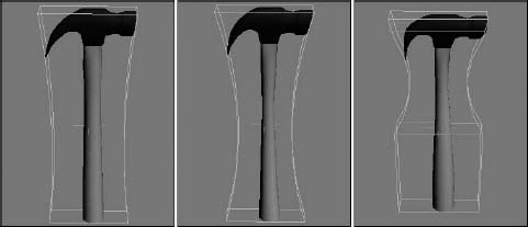
Axial Bulge is enabled with an Amount value of 0.2 and a Curve value of 2.0 in the left hammer in Figure 11.22; the middle hammer has also added Radial Squeeze values of 0.4 and 2.0; and the right hammer has an Upper Limit value of 8.
Twist modifier
The Twist modifier deforms an object by rotating one end of an axis in one direction and the other end in the opposite direction. Twist parameters include Angle and Bias values, a Twist Axis, and Limits.
The Angle value is the amount of twist in degrees that is applied to the object. The Bias value causes the twists to bunch up near the Pivot Point (for negative values) or away from the Pivot Point (for positive values).
FIGURE 11.22 The Squeeze modifier can bulge or squeeze along two different axes.
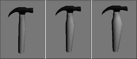
The left hammer in Figure 11.23 shows a twist angle of 120 about the Z-axis, the middle hammer shows a Bias value of 20, and the right hammer has an Upper Limit value of 8.
FIGURE 11.23 The Twist modifiers can twist an object about an axis.
Taper modifier
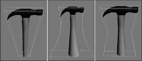
The Taper modifier scales one end of an object. The tapered end is the end opposite the Pivot Point. Taper parameters include the Amount and Curve, Primary and Effect Axes, and Limits. The Amount value defines the amount of taper applied to the affected end. The Curve value bends the taper inward (for negative values) or outward (for positive values). You can see the curve clearly if you look at the modifier's gizmo. For example, you can create a simple vase or a bongo drum with the Taper modifier and a positive Curve value.
The Primary Axis defines the axis about which the taper is applied. The Effect axis can be a single axis or a plane, and the options change depending on your Primary Axis. This defines the axis or plane along which the object's end is scaled. For example, if the Z-axis is selected as the Primary Axis, then selecting the XY Effect plane scales the object equally along both the X-axis and the Y-axis. Selecting the Y Effect axis scales the end only along the Y-axis. You can also select a Symmetry option to taper both ends equally. Taper limits work just like the Bend modifier.
The left hammer in Figure 11.24 shows a taper of 1.0 about the Z-axis; the middle hammer has a Curve value of –2; and the right hammer has the Symmetry option selected.
FIGURE 11.24 The Taper modifier can proportionally scale one end of an object.
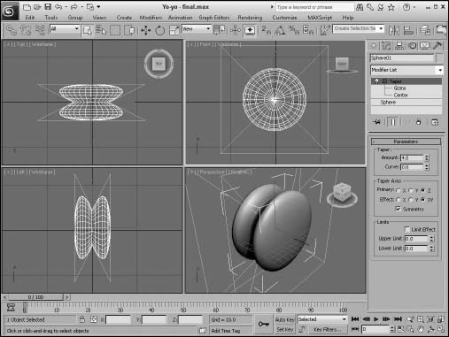
Tutorial: Creating a yo-yo
The Taper modifier can be used to create a variety of simple objects quickly, such as a yo-yo.
To create a yo-yo using the Taper modifier, follow these steps:
- Select Create Standard Primitives Sphere, and drag in the Front viewport to create a sphere object.
- With the sphere object selected, choose Modifiers Parametric Deformers Taper to apply the Taper modifier. Set the Taper Amount to 4.0 about the Primary Z-Axis and XY as the Effect plane, and enable the Symmetry option.
Figure 11.25 shows the resulting yo-yo; just add a string.
Substitute modifier
The Substitute modifier lets you place an object in the scene and substitute it with a higher-resolution object during render time. The substitute object may come from the scene or from an XRef file. To remove the substitute object, simply remove the Substitute modifier from the stack.
XForm modifier
The XForm modifier enables you to apply transforms such as Move, Rotate, and Scale to objects and/or subobjects. This modifier is applied by means of a gizmo that can be transformed using the transform buttons on the main toolbar. The XForm modifier has no parameters.
The XForm modifier solves a tricky problem that occurs during modeling. The problem happens when you scale, link, and animate objects in the scene, only to notice that the objects distort as they move. The distortion is caused because the transforms are the last action in the stack to be performed. So, when the object was first scaled and modifiers were applied, if you used the XForm modifier to do the scale transformation in the stack before the modifiers were applied, then the object's children won't inherit the scale transformation.
Note
XForm is short for the word transform.
FIGURE 11.25 The Taper modifier can be used to create a simple yo-yo.
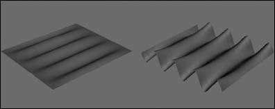
Wave modifier
The Wave modifier produces a wavelike effect across the surface of the object. All the parameters of the Wave Parameter are identical to the Ripple modifier parameters. The difference is that the waves produced by the Wave modifier are parallel, and they propagate in a straight line. Figure 11.26 shows the Wave modifier applied to a simple Quad Patch with values of 5 for Amplitude 1 and a Wave Length value of 50. The right Quad Patch also has an Amplitude 2 value of 20.
FIGURE 11.26 The Wave modifier produces parallel waves across the surface of an object.
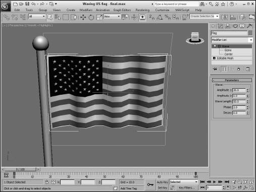
Tutorial: Waving a flag
The Wave modifier can add a gentle wave to an object such as a flag. If you animate the Phase value, you can show a flag unfurling in the breeze.
Cross-Reference
For a more realistic-looking flag, you can apply a Cloth modifier. See Chapter 29, “Adding and Styling Hair and Fur, and Using Cloth,” for more information on the Cloth modifier.
To animate a flag waving with the Wave modifier, follow these steps:
- Open the Waving US flag.max file from the Chap 11 directory on the CD.
This file includes a simple flag and flagpole made from primitive objects.
- With the flag selected, select the Modifiers Parametric Deformers Wave menu command to apply the Wave modifier to the flag.
- Notice how the waves run from the top of the flag to the bottom. You can change this by rotating the gizmo. Click the plus sign to the left of the Wave modifier in the Modifier Stack and select the Gizmo subobject. With the Select and Rotate tool (E), rotate the gizmo 90 degrees and then scale the gizmo with the Select and Scale tool (R) so it covers the flag object. Click the Gizmo subobject again to deselect gizmo subobject mode.
- Set Amplitude 1 to 25, Amplitude 2 to 0, and the Wave Length to 50. Then click the Auto Key button (N), drag the Time Slider to frame 100, and set the Phase value to 4. Click the Auto Key button (N) again to exit key mode.
Figure 11.27 shows the waving flag.
FIGURE 11.27 The Wave modifier can gently wave a flag.
Free Form Deformer modifiers
The Free Form Deformers category of modifiers causes a lattice to appear around an object. This lattice is bound to the object, and you can alter the object's surface by moving the lattice control points. Modifiers include FFD (Free Form Deformation) and FFD (Box/Cyl).
FFD (Free Form Deformation) modifier
The Free Form Deformation modifiers create a lattice of control points around the object. The object's surface can deform the object when you move the control points. The object is deformed only if it is within the volume of the FFD lattice. The three different resolutions of FFDs are 2 × 2, 3 × 3, and 4 × 4.
You can also select to display the lattice or the source volume, or both. If the Lattice option is disabled, only the control points are visible. The Source Volume option shows the original lattice before any vertices were moved.
The two deform options are Only In Volume and All Vertices. The Only In Volume option limits the vertices that can be moved to the interior vertices only. If the All Vertices option is selected, the Falloff value determines the point at which vertices are no longer affected by the FFD. Falloff values can range between 0 and 1. The Tension and Continuity values control how tight the lines of the lattice are when moved.
The three buttons at the bottom of the FFD Parameters rollout help in the selection of control points. If the All X button is selected, then when a single control point is selected, all the adjacent control points along the X-axis are also selected. This feature makes selecting an entire line of control points easier. The All Y and All Z buttons work in a similar manner in the other dimensions.
Use the Reset button to return the volume to its original shape if you make a mistake. The Conform to Shape button sets the offset of the Control Points with Inside Points, Outside Points, and Offset options.
To move the control points, select the Control Points subobject. This enables you to alter the control points individually.
FFD (Box/Cyl) modifiers
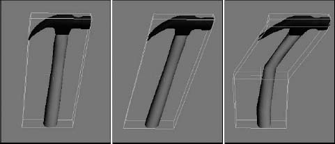
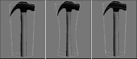
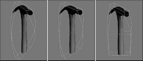
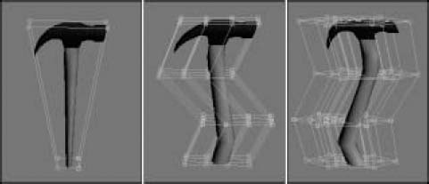
The FFD (Box) and FFD (Cyl) modifiers can create a box-shaped or cylinder-shaped lattice of control points for deforming objects. The Set Number of Points button enables you to specify the number of points to be included in the FFD lattice. Figure 11.28 shows how you can use the FFD modifier to distort the hammer by selecting the Control Point's subobjects. The left hammer is distorted using a 2 × 2 × 2 FFD, the middle hammer has a 4 × 4 × 4 FFD, and the right hammer is surrounded with an FFD (Cyl) modifier.
FIGURE 11.28 The FFD modifier changes the shape of an object by moving the lattice of Control Points that surround it.
Cross-Reference
The FFD (Box) and FFD (Cyl) lattices are also available as Space Warps. To learn more about Space Warps, see Chapter 42, “Using Space Warps.”
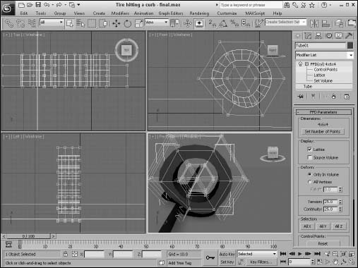
Tutorial: Modeling a tire striking a curb
The FFD modifiers are great for changing the shape of a soft-body object being struck by a solid object. Soft-body objects deform around the rigid object when they make contact. In this tutorial, you deform a tire hitting a curb.
To deform a tire striking a curb using an FFD modifier, follow these steps:
- Open the Tire hitting a curb.max file from the Chap 11 directory on the CD.
This file includes a simple tube object and a curb.
- With the tire selected, choose the Modifiers Free Form Deformers FFD Cyl menu option.
A cylinder gizmo appears around the tire.
- Click the FFD name in the Modifier Stack, and select the Control Points subobject from the hierarchy list. Then select all the center control points in the Left viewport, and scale the control points outward with the Select and Scale tool (R) to add some roundness to the tire.
- Then select all the control points in the lower-left corner of the Front viewport, and move these points diagonally up and to the right until the tire's edge lines up with the curb.
Figure 11.29 shows the tire as it strikes the hard curb.
FIGURE 11.29 This tire is being deformed via an FFD modifier.
Summary
With the modifiers contained in the Modify panel, you can alter objects in a vast number of ways. Modifiers can work with every aspect of an object, including geometric deformations, materials, and general object maintenance. In this chapter, you looked at the Modifier Stack and how modifiers are applied and examined several useful modifier sets. These topics were covered in this chapter:
- Working with the Modifier Stack to apply, reorder, and collapse modifiers
- Exploring the Selection modifiers
- Using the Parametric Deformer and FFD modifiers
Now that you have the basics covered, you're ready to dive into the various modeling types. The first modeling type on the list is splines and shapes, which is covered in the next chapter.