
CHAPTER 27
Working with Compound Objects
Understanding compound objects
Morphing objects
Using the Conform and ShapeMerge compound objects
Creating Terrain objects
Using the Mesher object
Using the Scatter and Connect compound objects
Working with BlobMesh objects
Lofting objects
Deforming lofted objects
Using ProBoolean and ProCutter objects
So far, I have covered a variety of modeling types, including shapes, meshes, and polys. The Compound Objects subcategory includes several additional modeling types that don't seem to fit anywhere else. As you will see in this chapter, these modeling types provide several new and unique ways to model objects, such as working with Boolean objects, scattering objects across the surface of another object, or lofting a cross section along a spline path.
Understanding Compound Object Types
The Compound Objects subcategory includes several unique object types. You can access these object types with the Create ![]() Compound menu or by clicking the Geometry category button in the Create panel and selecting Compound Objects in the subcategory drop-down list. All the object types included in the Compound Objects subcategory are displayed as buttons at the top of the Create panel. They include the following:
Compound menu or by clicking the Geometry category button in the Create panel and selecting Compound Objects in the subcategory drop-down list. All the object types included in the Compound Objects subcategory are displayed as buttons at the top of the Create panel. They include the following:
- Morph: Consists of two or more objects with the same number of vertices. The vertices are interpolated from one object to the other over several frames.
- Scatter: Randomly scatters a source object about the scene. You can also select a Distribution object that defines the volume or surface where the objects scatter.
- Conform: Wraps the vertices of one object onto another. You can use this option to simulate a morph between objects with different numbers of vertices.
- Connect: Connects two objects with open faces by joining the holes with additional faces.
- BlobMesh: Creates a metaball object that flows from one object to the next like water.
- ShapeMerge: Lets you embed a spline into a mesh object or subtract the area of a spline from a mesh object.
- Boolean: Created by performing Boolean operations on two or more overlapping objects. The operations include Union, Subtraction, Intersection, and Cut.
- Terrain: Creates terrains from the elevation contour lines like those found on topographical maps.
- Loft: Sweeps a cross-section shape along a spline path.
- Mesher: Creates an object that converts particle systems into mesh objects as the frames progress. This makes assigning modifiers to particle systems possible.
- ProBoolean: Replaces the original Boolean compound object with the ability to perform Boolean operations on multiple objects at a time.
- ProCutter: Cuts a single stock object into multiple objects using several cutter objects.
Note
When two or more objects are combined into a single compound object, they use a single object material. The Multi/Sub-Object Material type can be used to apply different materials to the various parts.
Morphing Objects
Morph objects are used to create a Morph animation by interpolating the vertices in one object to the vertex positions of a second object. The original object is called the Base object, and the second object is called the Target object. The Base and Target objects must have the same number of vertices. One Base object can be morphed into several targets.
Caution
To ensure that the Base and Target objects have the same number of vertices, create a copy of one object and modify it to be a target. Be sure to avoid such modifiers as Tessellate and Optimize, which change the number of vertices.
To morph a Base object into a Target, select the Base object and select Create ![]() Compound
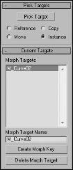
Compound ![]() Morph. Then click the Pick Target button in the Pick Targets rollout, shown in Figure 27.1, and select a Target object in the viewport. The cursor changes to a plus sign when it is over an acceptable object. Unavailable objects (that have a different number of vertices) cannot be selected. Pick Target options include Copy, Instance, Reference, and Move. (The Move option deletes the original object that is selected.) The Target object appears under the Current Targets rollout in the Morph Targets list.
Morph. Then click the Pick Target button in the Pick Targets rollout, shown in Figure 27.1, and select a Target object in the viewport. The cursor changes to a plus sign when it is over an acceptable object. Unavailable objects (that have a different number of vertices) cannot be selected. Pick Target options include Copy, Instance, Reference, and Move. (The Move option deletes the original object that is selected.) The Target object appears under the Current Targets rollout in the Morph Targets list.
Each Morph object can have several Target objects. You can use the Pick Target button to select several targets, and the order in which these targets appear in the list is the order in which they are morphed. To delete a Target object, select it from the list and click the Delete Morph Target button. Beneath the list is a Name field where you can change the name of the selected Target object.
FIGURE 27.1 A Morph rollout lets you pick targets and create morph keys.
Creating Morph keys
With a Target object name selected in the Morph Targets list, you can drag the Time Slider to a frame and set a Morph key by clicking the Create Morph Key button found at the bottom of the rollout. This option sets the number of frames used to interpolate among the different morph states.
Note
If the Morph object changes dramatically, set the Morph Keys to include enough frames to interpolate smoothly.
If a frame other than 0 is selected when a Target object is picked, a Morph Key is automatically created.
Morph objects versus the Morph modifier
Max includes two different ways to morph an object. You can create a Morph object or apply the Morph modifier to an existing object. The Morph object is different from the Morph modifier, but the results are the same; however, some subtle differences exist between these two.
A Morph object can include multiple Morph targets, but it can be created only once. Each target can have several Morph keys, which makes it easy to control. For example, you could set an object to morph to a different shape and return to its original form with only two Morph keys.
The Morph modifier, on the other hand, can be applied multiple times and works well with other modifiers, but the control for each modifier is buried in the Stack. The Parameters rollout options available for the Morph modifier are much more extensive than for the Morph object, and they include channels and support for a Morph material.
You can find more information on the Morph modifier in Chapter 21, “Understanding Animation and Keyframes.”
For the best of both worlds, apply the Morph modifier to a Morph object.
Tutorial: Morphing a woman's face
Although this example is fairly simple, it demonstrates a powerful technique that can be very helpful as you begin to animate characters. One of the key uses of morphing is to copy a character and move it about to create a new pose. You can then morph between the different poses to create smooth actions, gestures, or face motions.
To morph a woman's face, follow these steps:
- Open the Greek woman head morph.max file from the Chap 27 directory on the CD.
This file includes a woman's head. All objects have been attached to the face object to make working with it easy.
- Select the head object, and hold down the Shift key while dragging to the right in the Top viewport. In the Clone Options dialog box that opens, select Copy and set the Number of Copies to 2. Name one copy frown face and the other smiling face.
- Select the object named “smiling face,” and open the Modify panel. Zoom in around the mouth area, and enable Vertex subobject mode. Enable the Ignore Backfacing option in the Selection rollout, and turn on the Use Soft Selection option in the Soft Selection rollout with a Falloff value of 1.4. Then select the vertex at the corner of the mouth, and drag it upward in the Front viewport to make the woman smile. Repeat this action for the vertex on the opposite side of the mouth. Click the Vertex subobject button again to exit subobject mode.
- Select the original head object, and choose Create
 Compound Morph to make this object into a morph object. In the Pick Targets rollout, select the Copy option and click the Pick Target button. Then click the “frown face” object, or press the H key, and select it from the Select Objects dialog box. (Actually, it is the only object that you can select.) Then click the “smiling face” object. Both targets are now added to the list. Click the Pick Target button again to disable pick mode.
 - In the Morph Targets list, select the “frown face” object and click the Create Morph Key button. Then drag the Time Slider (below the viewports) to frame 50, select the “smiling face” object in the Morph Targets list, and press the Create Morph Key button again.
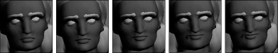
- Click the Play button (in the Time Controls section at the bottom of the Max window) to see the morph. The woman's head object morphs when you move the Time Slider between frames 0 and 50. Figure 27.2 shows different stages of the morph object.
FIGURE 27.2 A woman's face being morphed to a smile
Creating Conform Objects
Conform compound objects mold one object over the surface of another. This compound object is useful for adding geometric details to objects, such as stitches to a baseball or a quilt.
The object that is modified is called the Wrapper object. The other object is the Wrap-To object. These objects need to be either mesh objects or objects that you can convert to mesh objects.
Cross-Reference
Another way to mold one object over the surface of another is with the Conform Space Warp. Find out more about this Space Warp in Chapter 42, “Using Space Warps.”
To create a Conform object, select an object to be the Wrapper object and select Create ![]() Compound
Compound ![]() Conform. To select the Wrap-To object, click the Pick Wrap-To Object button in the Pick Wrap-To Object rollout and choose one of the options below the button (Reference, Move, Copy, or Instance).
Conform. To select the Wrap-To object, click the Pick Wrap-To Object button in the Pick Wrap-To Object rollout and choose one of the options below the button (Reference, Move, Copy, or Instance).
Caution
Shapes and splines cannot be used as either the Wrapper or Wrap-To objects, even if they are renderable.
In the Parameters rollout, shown in Figure 27.3, the Objects section lists both the Wrapper and Wrap-To objects. Name fields are also available for changing the names of both objects.
FIGURE 27.3 The Parameters rollout of the Conform object lets you define how the object is wrapped.
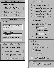
The Wrapper Parameters section includes two adjustable values: Default Projection Distance, which is the distance that the Wrapper moves if it doesn't intersect with the Wrap-To object, and Standoff Distance, which is the distance between the Wrapper and the Wrap-To object. The Use Selected Vertices option causes only the selected vertices passed up the Stack to be moved.
Setting a vertex projection direction
The Parameters rollout also includes controls for specifying the Vertex Projection Direction settings. You can select to project the vertices based on the current active viewport with the Use Active Viewport option. If the view changes, you can use the Recalculate Projection button to compute the new projection direction.
You can also use the local Z-axis of any object in the scene as the projection direction. The Pick Z-Axis Object button lets you select the object to use. After you have selected it, rotating this object can alter the projection direction. The name of the object is displayed below the Pick Z-Axis Object button.
Other projection options include Along Vertex Normals, Towards Wrapper Center, Towards Wrapper Pivot, Towards Wrap-To Center, and Towards Wrap-To Pivot. The Along Vertex Normals option sets the projection direction opposite the Wrapper's normals. The other options set the direction toward the center or pivot of the Wrapper or Wrap-To objects.
Tutorial: Placing a facial scar
As an example of the Conform object, you'll add a gruesome scar to the face of a character. Using the Conform compound object, details like this scar can be a mesh object and still perfectly match the contour of the face object.
To create a facial scar using the Conform object, follow these steps:
- Open the Facial scar.max file from the Chap 27 directory on the CD.
This file includes a face mesh with a mesh scar placed to its side. The face mesh was created by Viewpoint Datalabs.
- Click the Select and Move button on the main toolbar, and select and move the scar to position it in front of the face mesh in the Front and Top viewports.
- With the scar selected, choose the Create Compound Conform menu command.
- Under the Parameters rollout, select the Use Active Viewport option and make sure that the Front viewport is active. In the Wrapper Parameters section, set the Standoff Distance value to 3.0.
- Click the Pick Wrap-To Object button, and click the face mesh. Select the Instance option.
- The mesh gets the default object color, but you can see the original materials if you select the Display Operands option at the bottom of the Parameters rollout.
Tip
After using the Conform compound object, the object type is set to Conform, but if you collapse the stack to an Editable Poly, you'll be able to edit the resulting object.
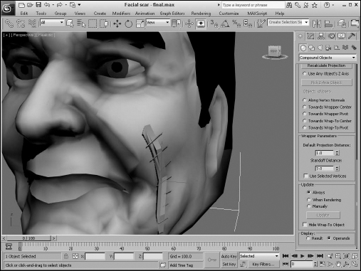
Figure 27.4 shows a close-up of the surgery in the maximized Perspective view.
FIGURE 27.4 A patch grid being conformed to the front of a face object
Creating a ShapeMerge Object
The ShapeMerge compound object enables you to use a spline shape as a cookie cutter to extract a portion of a mesh object. This button is enabled only if a mesh object and a spline exist in the scene. To use this object, select a mesh object and click the Pick Shape button in the Pick Operand rollout, and then select a spline shape. The shape can be a Reference, Move, Instance, or Copy.
The spline shape is always projected toward its negative Z-axis. By rotating and positioning the spline before selecting it, you can apply it to different sides of an object. You can apply multiple shapes to the same mesh object.
Caution
If you're using the Nitrous display driver, you may need to convert the ShapeMerge object to an Editable Poly object before it displays correctly in the viewports.
The Parameters rollout, shown in Figure 27.5, displays each mesh and shape object in a list. You can also rename either object using the Name field. The Extract Operand button lets you separate either object as an Instance or a Copy.
FIGURE 27.5 Use the Parameters rollout for the ShapeMerge compound object to cut or merge a shape.
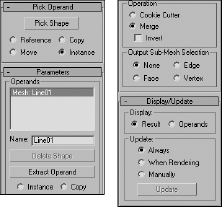
Cookie Cutter and Merge options
The Operations group includes options for cutting the mesh, including Cookie Cutter and Merge. The Cookie Cutter option cuts the shape out of the mesh surface, and the Merge option combines the spline with the mesh. You can also Invert the operation to remove the inside or outside of the selected area.
Like the Boolean Subtraction operations, the Cookie Cutter option can remove sections of the mesh, but it uses the area defined by a spline instead of a volume defined by a mesh object. The Merge option is useful for marking an area for selection. Figure 27.6 shows a ShapeMerge object with the Cookie Cutter option selected.
Note
You can use the Merge option to create a precise face object that can be used with the Connect object.
The Output Sub-Mesh Selection option lets you pass the selection up the Stack for additional modifiers. Options include None, Face, Edge, and Vertex.
Note
To see the backsides of the faces, right-click the object, select Properties from the pop-up menu, and disable the Backface Cull option.
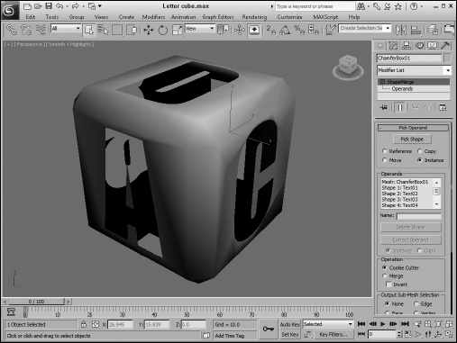
Tutorial: Using the ShapeMerge compound object
When outlined text is imported into Max, it typically contains letters that have shapes within shapes. For example, the letter p, when outlined, includes the outline of the letter p and a circle shape to denote the interior section of the letter. When outline text like this is converted to a mesh object, both the letter outline and its interior section are covered, making the text illegible. You can use the ShapeMerge compound object to remedy this tricky situation.
You can practice handling this situation using the logo for the fictional Box It Up company. Before this logo can be extruded, you need to do some work involving the ShapeMerge object.
FIGURE 27.6 A ShapeMerge object using the Cookie Cutter option
To use the ShapeMerge object to remove the center area from an extrusion, follow these steps:
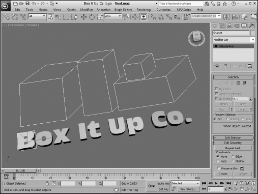
- Open the Box It Up Co logo.max file from the Chap 27 directory on the CD.
- Select all the letters in the logo, press the Alt key, and deselect the interior shapes in the B, O, and P letters. Then apply the Modifiers Mesh Editing Extrude modifier with an Amount value of 0.010 feet.
- Select the letter B shape again. Then select the Create Compound ShapeMerge menu command.
- Set the Operation to Cookie Cutter, and click the Pick Shape button in the Pick Operand rollout with the Copy option. Select the two interior shapes for the letter B. Then click the Select Object button on the main toolbar again to exit ShapeMerge mode. Then repeat this step for the letters O and P.
- If the interior of the ShapeMerge letters is still visible, select each and convert it to an Editable Poly object by right-clicking its type in the Modifier Stack and selecting Editable Poly.
Figure 27.7 shows the finished logo. Notice that the letters have the interior sections removed.
FIGURE 27.7 The logo with the interior centers removed from extruded letters using the ShapeMerge object
Creating a Terrain Object
The Terrain object is a great object that enables you to create terrains from splines representing elevation contours. These contour splines can be created in Max or imported using a format like AutoCAD's DWG. If the splines are created in Max, make sure that each contour spline is a separate object. The splines all must be closed splines. If all the splines have an equal number of vertices, then the resulting terrain object is much cleaner. You can ensure this by copying and scaling the base spline.
To create a terrain, create splines at varying elevations, select all the splines, and click the Terrain button. The Terrain button is available only if closed splines are selected. You can use the Pick Operand button in the Pick Operand rollout to select additional splines to add to the Terrain object. All splines in the object become operands and are displayed in the Operands list.
The Form group includes three options that determine how the terrain is formed: Graded Surface, Graded Solid, and Layered Solid. The Graded Surface option displays a surface grid over the contour splines; the Graded Solid adds a bottom to the object; and the Layered Solid displays each contour as a flat, terraced area. The Stitch Border option causes polygons to be created to close open splines by creating a single edge that closes the spline. The Retriangulate option optimizes how the polygons are divided to better represent the contours.
The Display group includes options to display the Terrain mesh, the Contour lines, or Both. You can also specify how you want to update the terrain.
The Simplification rollout lets you alter the resolution of the terrain by selecting how many vertical and horizontal points and lines to use. Options include using all points (no simplification), half of the points, a quarter of the points, twice the points, or four times the points.
Coloring elevations
The Color by Elevation rollout, shown in Figure 27.8, displays as reference the Maximum and Minimum Elevations. Between these is a Reference Elevation value, which is the location where the landmass meets the water. Entering a Reference Elevation and clicking the Create Defaults button automatically creates several separate color zones. You can add, modify, or delete zones using the Add, Modify, or Delete Zone buttons.
FIGURE 27.8 The Color by Elevation rollout lets you change the color for different elevations.
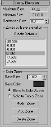
You can access each color zone from a list. To change a zone's color, select it and click the color swatch. You can set colors to Blend to the Color Above or to be Solid to Top of Zone.
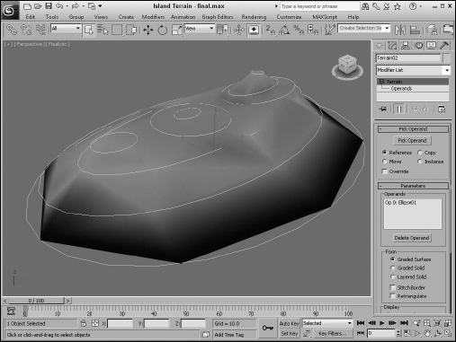
Tutorial: Creating an island with the Terrain compound object
In this tutorial, you create a simple island. The Color by Elevation rollout makes distinguishing the water from the land easy.
To create an island using the Terrain object, follow these steps:
- Select Create Shapes Ellipse, and drag in the Top view to create several ellipses of various sizes representing the contours of the island.
The first ellipse you create should be the largest, and the ellipses should get progressively smaller.
- In the Left view, select and move the ellipses up and down so that the largest one is on the bottom and the smallest one is on top. You can create two smaller hills by including two ellipses at the same level.
Note
If you create the ellipses in the proper order from largest to smallest, then you can use the Select All command. If not, then select the splines in the order that they'll be connected from top to bottom before clicking on the Terrain button.
- Use the Edit Select All (Ctrl+A) menu command to select all the ellipses, and select Create Compound Terrain.
The ellipses automatically join together. Joining all the ellipses forms the island.
- In the Color by Elevation rollout, select a Reference Elevation of 5 and click the Create Defaults button.
This automatically creates color zones for the island. The elevation values for each zone are displayed in a list within the Color by Elevation rollout. Selecting an elevation value in the list displays its color in the color swatch.
- Select each elevation value individually, and set all Zones to Blend to the Color Above option for all zones, except for the Zone with the lightest blue.
This creates a distinct break between the sea and the land of the island.
Figure 27.9 shows the final terrain. In an example later in this chapter, you'll use the Scatter compound object to add trees to the small terrain island.
Using the Mesher Object
You can use the Mesher compound object to convert objects to mesh objects on the fly as an animation progresses. This feature is useful for objects such as particle systems. After you convert the object to a mesh object, you can apply modifiers that weren't possible before, such as Optimize, UVW Map, and others.
Another benefit of the Mesher object is that you can apply several complex modifiers to a single Mesher object and load it to a particle system rather than applying the modifiers to all the pieces that make up a particle system.
The Parameters rollout of the Mesher object includes a Pick Object button. Click this button, and select an object in the viewport to make the selected object an instance of the Mesher object. This action does not delete the original object, and the Mesher instance is oriented to the Mesher object's coordinate system. The object name then appears on the button. You can change the object by clicking the button again and selecting a new object.
Caution
Do not delete the original object, or the Mesher instance also disappears. If you want to render only the Mesher instance, then select the original object and hide it using the Tools ![]() Display Floater command.
Display Floater command.
The Time Offset is the number of the frames ahead (values can be negative) or behind the original object that the animation should progress. If the Build Only at Render Time option is set, then the Mesher instance is not visible in the viewports but shows up in the final rendered image. You can use the Update button to manually force an update of the Mesher instance after the settings for the original object have been modified.
FIGURE 27.9 A Terrain island created with the Terrain compound object
When you use the Mesher object to create an instance of a particle system, the bounding box of the particle system as it streams the particles becomes long and thin over time. This long, thin bounding box can potentially cause problems with certain modifiers. You can prevent these problems by selecting an alternative bounding box that doesn't change over time. To select a new bounding box, select the Custom Bounding Box option, click the Pick Bounding Box button, and click an object in the viewport. You can select the original object as the new bounding box. With the Mesher object selected, the bounding box is shown in orange wherever it is located. The corner coordinates of the custom bounding box are displayed under the Pick Bounding Box button. Mesher objects can also be used as Particle Flow events, using the Add and Remove buttons at the bottom of the Parameters rollout.
Cross-Reference
Chapter 41, “Creating Particles and Particle Flow,” provides more information on working with particle systems.
Working with BlobMesh Objects
BlobMesh objects are simple spheres. If you have only one of them, they aren't interesting at all, but if you get them together, they run into each other much like the metal mercury. This makes them an ideal choice for modeling flowing liquids and soft organic shapes.
BlobMesh objects are used as sets of objects rather than as individual objects. If you click the BlobMesh button in the Compound Objects subcategory and then create a BlobMesh in the viewports, it appears as a sphere with the radius set using the Size parameter. The real benefit comes from clicking the Pick or Add buttons below the Blob Objects list and selecting an object in the scene.
Note
The Pick, Add, and Remove buttons become enabled only in the Modify panel.
The object that is picked is added to the Blob Objects list, and each vertex of the object gets a BlobMesh added to it. If the BlobMesh objects are large enough to overlap, then the entire object is covered with these objects, and they run together to form a flowing mass of particles.
Setting BlobMesh parameters
The Size value sets the radius of the BlobMesh object. Larger sizes result in more overlapping of surrounding objects. For particle systems, the Size is discounted, and the size of the particles determines the size of the BlobMesh objects. The Tension value sets how loose or tight the surface of the BlobMesh object is. Small tension values result in looser objects that more readily flow together.
The Evaluation Coarseness value sets how dense the BlobMesh objects will be. By enabling the Relative Coarseness option, the density of the objects changes as the size of the objects changes. The Coarseness values can be different for the viewport and the Render engine.
When a BlobMesh object is selected and applied to the picked object, each vertex has an object attached to it, but if you apply a selection modifier, such as the Mesh Select modifier, to the picked object, then only the selected subobjects get a BlobMesh object. You also can use the Soft Selection option to select those subobjects adjacent to the selected subobjects. The Minimum Size value is the smallest-sized BlobMesh object that is used when Soft Selection is enabled.
The Large Data Optimization option is a quicker, more efficient way of rendering a huge set of BlobMesh objects. The benefit from this method comes when more than 2,000 BlobMesh objects need to be rendered. If the viewport updates are slow because of the number of BlobMesh objects, you can select to turn them Off in Viewport.
Cross-Reference
When BlobMesh objects are applied to a particle system, they can be used as part of a Particle Flow workflow. The Particle Flow Parameters rollout includes a list of events to apply to the BlobMesh objects. Particle Flow is covered in detail in Chapter 41, “Creating Particles and Particle Flow.”
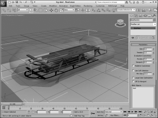
Tutorial: Creating icy geometry with BlobMesh
The BlobMesh object can be combined with a geometry object to create the effect of an object that has been frozen in ice. Using the BlobMesh's Pick feature, you can select a geometry object, and a BlobMesh is placed at each vertex of the object. I suggest using an object with a fairly limited number of vertices.
To create the effect of an object covered in ice, follow these steps:
- Open the Icy sled.max file from the Chap 27 directory on the CD.
This file includes a sled model created by Viewpoint Datalabs.
- With the sled selected, choose Create Compound BlobMesh, and create a simple BlobMesh by simply clicking in the Top viewport. Set the Size value to 6.0. Then right-click to exit BlobMesh mode, click the Pick button in the Parameters rollout, and select the Sled object.
- Press the M key to open the Material Editor, and select the first sample slot. Change the Diffuse color to a light blue, and set the Opacity to 20. Then increase the Specular Level to 90 and the Glossiness to 40, and apply the material to the BlobMesh object.
- Render the Perspective View window to see the final result. The sled is embedded in ice.
Figure 27.10 shows the resulting sled, all ready to be defrosted.
FIGURE 27.10 BlobMesh objects can be used to cover objects in ice.
Creating a Scatter Object
A Scatter object spreads multiple copies of the object about the scene or within a defined area. The object that is scattered is called the Source object, and the area where the scatter objects can be placed is defined by a Distribution object.
Particle systems, which are discussed in Chapter 41, “Creating Particles and Particle Flow,” can also create many duplicate objects, but you have more control over the placement of objects with a Scatter object.
To create a Scatter object, choose an object that will be scattered over the surface and select the Create ![]() Compound
Compound ![]() Scatter menu command. The selected object becomes the Source object. A rollout then opens, in which you can select the Distribution object or use defined transforms.
Scatter menu command. The selected object becomes the Source object. A rollout then opens, in which you can select the Distribution object or use defined transforms.
Under the Scatter Objects rollout, the Objects section lists the Source and Distribution objects. Name fields are also available for changing the name of either object. The Extract Operand button is available only in the Modify panel; it lets you select an operand from the list and make a copy or instance of it.
Note
The placement of the Source object on the distribution object is determined by the Source object's pivot point.
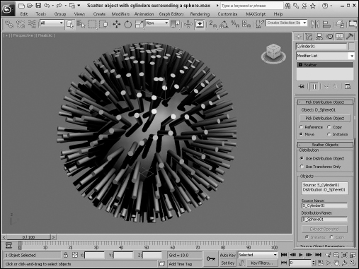
Working with Source objects
The Source object is the object that is to be duplicated. Figure 27.11 shows a Cylinder primitive scattered over a spherical Distribution object with 500 duplicates. The Perpendicular and Distribute Using Even options are set.
FIGURE 27.11 A Scatter object made of a Cylinder spread over an area defined by a sphere
In the Scatter Objects rollout are several parameters for controlling the Source object. In the Source Object Parameters section, the Duplicates value specifies how many objects to scatter. You can also specify a Base Scale and the Vertex Chaos values. The Base Scale is the value that the object is scaled to before being scattered. All new objects are scaled equally to this value. The Vertex Chaos button randomly distributes the object vertices.
The Animation Offset defines the number of frames between a new duplicate and the previous one.
Note
If you look closely at a Scatter object, you'll notice that both the Source and Distribution objects have the same object color. To color them differently, use the Multi/Sub-Object Material.
Working with Distribution objects
To select a Distribution object, click the Pick Distribution Object button and select an object in the viewport. (Make sure that the Use Distribution Object option is selected in the Scatter Objects rollout.) You can specify the Distribution object as a Copy, Instance, Reference, or Move.
Under the Distribution Object Parameters section are several options for controlling the Distribution object. The Perpendicular option causes the Source objects to be aligned perpendicular to the Distribution object. If the Perpendicular option is disabled, the orientation remains the same as that of the default Source object. Figure 27.12 shows the same Scatter object as in the preceding figure, but with several different options.
FIGURE 27.12 A Scatter object with different options: Base Scale at 20%, Vertex Chaos at 2.0, Perpendicular option disabled, and Duplicates at 100
The Use Selected Faces Only option enables you to select the faces over which the duplicates are positioned. The Selected Faces are those passed up the Stack by the Mesh Select modifier.
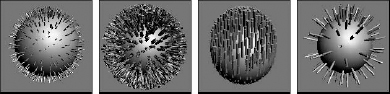
Other Distribution object parameter options include Area, Even, Skip N, Random Faces, Along Edges, All Vertices, All Edge Midpoints, All Face Centers, and Volume. The Area option evenly distributes the objects over the surface area, and the Even option places duplicates over every other face. The Skip N option lets you specify how many faces to skip before placing an object. The Random Faces and Along Edges options randomly distribute the duplicates around the Distribution object. The All Vertices, All Edge Midpoints, and All Face Centers options ignore the Duplicates value (which specifies the number of duplicates) and place a duplicate at every vertex, edge midpoint, and face. Figure 27.13 shows several of these options.
FIGURE 27.13 A Scatter object with different distribution options: Area, Skip N where N=7, Random Faces, All Vertices, and All Face Centers
All the options described thus far place the duplicates on the surface of the object, but the Volume option scatters the duplicates inside the Distribution object's volume.
Setting Transforms
The Transforms rollout is used to specify the individual transformation limits of the duplicate objects. For example, if the Z-axis value is set to 90, then each new duplicate is randomly rotated about its local Z-axis at a distance somewhere between –90 and 90.
You can use these transformations with a Distribution object or by themselves if the Use Transforms Only option is selected under the Scatter Objects rollout. The Use Maximum Range option causes all three axes to adopt the same value. The Lock Aspect Ratio option maintains the relative dimensions of the Source object to ensure uniform scaling.
Speeding updates with a proxy
Working with a large number of duplicates can slow the viewport updates to a crawl. To speed these updates, select the Proxy option in the Display rollout. This option replaces each duplicate with a wedge-shaped object. For example, if you used the Scatter object to place people on a sidewalk, you can use the Proxy option to display simple cylinders in the viewports instead of the details of the person mesh.
Another way to speed the viewport updates is to use the Display spinner. Using this spinner, you can select a percentage of the total number of duplicates to display in the viewport. The rendered image still uses the actual number specified.
The Hide Distribution Object option lets you make the Distribution object visible or invisible. The Seed value is used to determine the randomness of the objects.
Loading and saving presets
With all the various parameters, the Load/Save Presets rollout enables you to Save, Load, or Delete various presets. You can use saved presets with another Source object.
Tutorial: Covering the island with trees
You can combine several different types of compound objects to create interesting effects. In this tutorial, you use the Scatter object to add trees to the Terrain object island created earlier in this chapter.
To add trees to the island with the Scatter object, follow these steps:
- Open the Island terrain with trees.max file from the Chap 27 directory on the CD.
This file is the same island terrain example that you completed earlier in this chapter, but it also has a simple tree added to it.
- With the tree object selected, select the Create Compound Scatter menu command.
- Click the Pick Distribution Object button, and select the island terrain. Set the number of Duplicates to 100, and disable the Perpendicular option.
All the trees now stand upright.
- Select the Random Faces option.
The trees become denser around the hills where there are more faces.
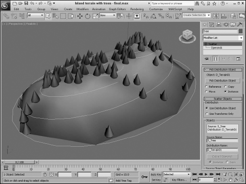
Figure 27.14 shows the island with the trees.
FIGURE 27.14 Using the Scatter object, you can add trees to your island terrain.
Creating Connect Objects
A Connect object is useful for building a connecting bridge between two separate objects. Each object must have an open face or hole that specifies where the two objects are to be connected.
To use this object, delete a face on two Editable Mesh objects and then position the holes across from each other. Select one of the objects, and choose the Create ![]() Compound
Compound ![]() Connect menu command. Then, click the Pick Operand button, and select the second object. The Connect object builds the additional faces required to connect the two holes.
Connect menu command. Then, click the Pick Operand button, and select the second object. The Connect object builds the additional faces required to connect the two holes.
Filling object holes
If multiple holes exist between the objects, the Connect object attempts to patch them all. You can also use the button several times to connect a single object to multiple objects.
Caution
The Connect object doesn't work well with NURBS (Non-Uniform Rational B-Splines) objects.
The Parameters rollout includes a list of all the operands or objects involved in the connection. You can delete any of these with the Delete Operand button. The Extract Operand button lets you separate the Operand object from the Connect object.
In the Interpolation section, the Segments value is the number of segments used to create the bridge section, and the Tension value is the amount of curvature to use in an attempt to smooth the connected bridge.
The Bridge Smoothing option smoothes the faces of the bridge, and the Ends option smoothes where the bridge and the original objects connect.
Tutorial: Creating a park bench
The Connect object is best used between two symmetrical copies of an object that need to be attached, as with a table or bridge. For this tutorial, you use the Connect object to create a park bench between two end pieces.
Note
Although the Connect compound object works fine, it requires that both holes have the same number of vertices. A more robust solution is the Editable Poly's Bridge feature.
To connect two ends of a park bench, follow these steps:
- Open the Park bench.max file from the Chap 27 directory on the CD.
This file includes symmetrical ends of the park bench. One end was created by extruding a spline shape and using the ShapeMerge tool to cut matching holes on the inner-facing surfaces. The Mirror tool was then used to create and rotate the symmetrical clone.
- Select one end of the park bench, and select the Create Compound Connect menu command.
- In the Pick Operand rollout, click the Pick Operand button, select the Move option, and click on the opposite side of the park bench.
The two end pieces connect.
- In the Parameters rollout, select the Smoothing: Bridge option to smooth the seat of the bench.
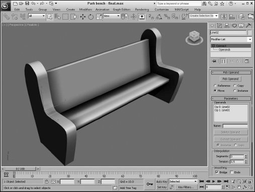
Figure 27.15 shows the resulting park bench.
FIGURE 27.15 A Connect compound object can join two open holes in separate objects.
Creating a Loft Object
Lofting is a term that comes from the shipbuilding industry. It describes a method for building ships that creates and positions the cross sections and then attaches a surface or skin along the length of the cross sections.
To create a Loft object, you need to have at least two spline shapes: one shape that defines the path of the Loft and another shape that defines its cross section. After the shapes are created, select the Create ![]() Compound menu command. A Loft button is enabled if two or more splines are present in the viewport.
Compound menu command. A Loft button is enabled if two or more splines are present in the viewport.
Tip
Be aware of the orientation of the cross-section shape and the loft path before the loft is applied. The cross section's local Z-axis is always aligned with the path's local Y-axis. By making the correct orientations before applying the loft, you can save some headache. If the orientations aren't correct, you can edit the pivot on either object.
Using the Get Shape and Get Path buttons
After you click the Loft button, the Creation Method rollout displays the Get Path and Get Shape buttons, which you use to specify which spline is the path and which spline is the cross section. Select a spline, and then click either the Get Path button or the Get Shape button. If you click the Get Shape button, the selected spline is the path, and the next spline shape you select is the cross section. If you click the Get Path button, the selected spline is the shape, and the next spline shape you select is the path.
Note
After you click the Get Path or Get Shape button, although the cursor changes when you're over a valid spline, not all spline shapes can be used to create Loft objects. For example, you cannot use a spline created with the Donut button as a path.
When creating a Loft object with the Get Shape and Get Path buttons, you can specify either to Move the spline shape or to create a Copy or an Instance of it. The Move option replaces both splines with a Loft object. The Copy option leaves both splines in the viewport and creates a new Loft object. The Instance option maintains a link between the spline and the Loft object. This link enables you to modify the original spline. The Loft object is updated automatically.
The vertex order of the path spline is important. The Loft object is created starting at the vertex numbered 1.
Note
You can tell which vertex is the first by enabling Vertex Numbering in the Selection rollout of an editable spline. The first vertex is also identified with a yellow box.
Controlling surface parameters
All Loft objects include the Surface Parameters rollout. Using this rollout, you can set the smoothing of the Loft object with two different options: Smooth Length and Smooth Width. You can use the Mapping options to control the mapping of textures by setting values for the number of times the map repeats over the Length or Width of the Loft. The Normalize option applies the map to the surface evenly or proportionately according to the shape's vertex spacing. You can set the Loft object to automatically generate Material and Shape IDs, and you can specify the output of the Loft to be either a Patch or Mesh.
Changing path parameters
The Path Parameters rollout, shown in Figure 27.16, lets you position several different cross-sectional shapes at different positions along the Loft path. The Path value indicates either the Distance or Percentage along the path where this new shape should be located. The Snap option, if turned on, enables you to snap to consistent distances along the path. The Path Steps option enables you to place new shapes at steps along the path where the vertices are located. Each path will have a different number of steps, depending on its complexity.
FIGURE 27.16 The Loft compound object rollouts

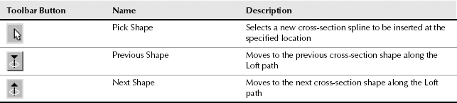
The viewport displays a small yellow X at the location where the new cross-sectional shape will be inserted. At the bottom of the rollout are three buttons, which are illustrated and described in Table 27.1.
TABLE 27.1 Path Rollout Buttons
Setting skin parameters
The Skin Parameters rollout includes many options for determining the complexity of the Loft skin. You can specify whether to cap either end of the Loft using the Cap Start and/or Cap End options. The caps can be either Morph or Grid type.
This rollout also includes the following options for controlling the look of the skin:
- Shape and Path Steps: Sets the number of segments that appear in each spline's cross-sectional shape and between each division along the path. The straight segments are ignored if the Optimize Path option is selected.
- Optimize Shapes and Paths: Reduces the Loft's complexity by deleting any unneeded edges or vertices.
- Adaptive Path Steps: Automatically determines the number of steps to use for the path in order to maintain a smooth curve.
- Contour: Determines how the cross-sectional shapes line up with the path. If this option is enabled, the cross section is aligned to be perpendicular to the path at all times. If disabled, this option causes the cross-sectional shapes to maintain their orientation as the path is traversed.
- Banking: Causes the cross-section shape to rotate as the path bends.
- Constant Cross-Section: Scales the cross-sectional shapes in order to maintain a uniform width along the path. Turning off this option causes the cross sections to pinch at any sharp angles along the path.
- Linear Interpolation: Causes straight linear edges to appear between different cross-sectional shapes. Turning off this option causes smooth curves to connect various shapes.
- Flip Normals: Used to correct difficulties that would appear with the normals. Often the normals are flipped accidentally when the Loft is created.
- Quad Sides: Creates four-sided polygons to connect to adjacent cross-section shapes with the same number of sides.
- Transform Degrade: Makes the Loft skin disappear when subobjects are transformed. This feature can help you better visualize the cross-sectional area while it is being moved.
The Display options at the bottom of the Skin Parameters rollout give you the choice of displaying the skin in all viewports or displaying the Loft skin only in the viewports with shading turned on.
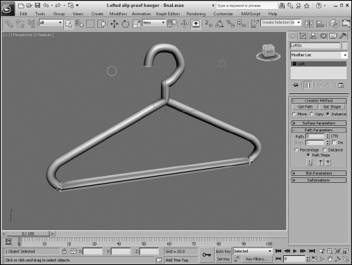
Tutorial: Designing a slip-proof hanger
As an example of creating a Loft object with different cross-sectional shapes, you'll design a new hanger that includes some rough edges along its bottom section to keep slacks from sliding off.
To design a hanger Loft object with different cross sections, follow these steps:
- Open the Lofted slip-proof hanger.max file from the Chap 27 directory on the CD.
This file includes a spline outline of a hanger and two simple shapes.
- Select the hanger spline, and choose the Create Compound Loft menu command.
- In the Creation Method rollout, click the Get Shape button and then click the small circle shape (make sure that the Copy option is selected).
This lofts the entire hanger with a circular cross section.
- In the Path Parameters rollout, select the Path Steps option. A dialog box appears warning that this may change the relocate shapes. Click Yes to continue. Increment the Path value until the yellow X marker in the viewport is positioned at the beginning of the hanger's bottom bar (at Step 53 for this tutorial). Click the Get Shape button again, and click the small circular shape again.
This extends the circular cross section from the start at Step 0 to Step 53.
- Increment the Path value by 1 to Step 54, click the Get Shape button, and select the star shape. This makes the remainder of the hanger use a star-shaped cross section. Increment the Path value again to the end of the hanger's bottom bar (at Step 60), click the Get Shape button, and select the star shape again to end the star cross section.
- In the Path Parameters rollout, increment the Path value a final time to Step 61, click the Get Shape button, and click the circular shape. Click the Pick Shape icon button at the bottom of the Path Parameters dialog box to change the cross section of the hanger to the end of the path. Right-click in the viewport to exit Get Shape mode.
Figure 27.17 shows the finished designer hanger.
FIGURE 27.17 A lofted hanger created with two different cross-sectional shapes
Deforming Loft objects
When you select a Loft object and open the Modify panel, the Deformation rollout appears. This rollout includes five buttons that let you Scale, Twist, Teeter, Bevel, and Fit the cross-section shapes along the path. All five buttons open similar graph windows that include control points and a line that represents the amount of the effect to apply. Next to each button is a toggle button with a light switch on it. This button enables or disables the respective effect.
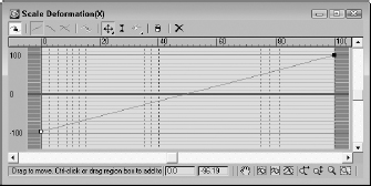
The Deformation window interface
All five deformation options use the same basic window and controls. The vertical lines within the window represent the placement of vertices on the loft path. As an example of the Deformation window interface, Figure 27.18 shows the Scale Deformation window.
FIGURE 27.18 The Deformation dialog box interface lets you control the cross section over the length of the path.
Dragging the curve directly can modify the deformation curve. You can also insert control points at any location along the curve. These control points can be one of three different types: Corner, Bézier Corner, or Bézier Smooth. Bézier type points have handles for controlling the curvature at the point. To change the point type, select the point and right-click. Then make your selection from the pop-up menu. The end points must always be either Corner or Bézier Corner type.
To move a control point, select and drag it or enter a horizontal and/or vertical value in the fields at the bottom of the window.
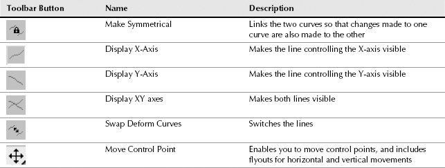
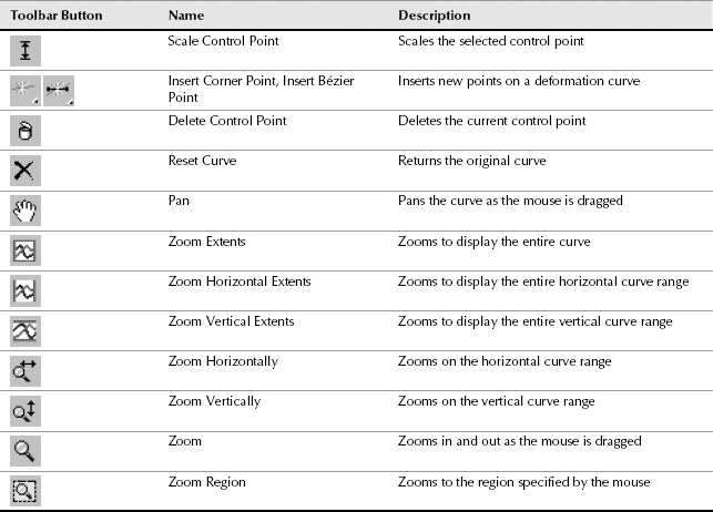
Table 27.2 describes the buttons at the top of the Deformation window.
TABLE 27.2 Deformation Dialog Box Buttons
Note
Several buttons are disabled on the Twist and Bevel Deformation windows because these dialog boxes have only one deformation curve.
At the bottom of the Deformation dialog boxes are two value fields. The value fields display the X and Y coordinate values for the currently selected point. The navigation buttons enable you to pan and zoom within the dialog box.
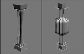
Figures 27.19 and 27.20 show the various deformation options applied to a lofted column.
FIGURE 27.19 The Loft compound object deformation options: Scale, Twist, and Teeter
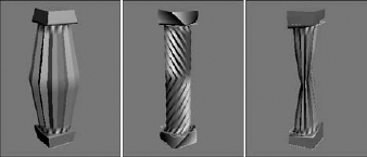
FIGURE 27.20 The Loft compound object deformation options: Bevel and Fit
Scale Deformation
The Scale Deformation window can alter the relative scale of the Loft object at any point along its path. This window includes two lines: one red and one green. The red line displays the X-axis scale, and the green line displays the Y-axis scale. By default, both lines are positioned equally at the 100 percent value. Specifying a value greater than 100 percent increases the scale, and specifying a value less than 100 percent has the opposite effect.
Twist Deformation
The Twist Deformation rotates one cross section relative to the others along the shape's local Z-axis and can be used to create an object that spirals along its path. This option is similar to the Banking option, which can also produce rotations about the path.
The Twist Deformation window includes only one red line representing the rotation value. By default, this line is set to a 0-degree rotation value. Positive values result in counterclockwise rotations, and negative values have the opposite effect.
Teeter Deformation
Teeter Deformation rotates a cross section so that its outer edges move closer to the path. This is done by rotating the cross section about its local X-axis or Y-axis. The result is similar to that produced by the Contour option.
The Teeter Deformation window includes two lines: one red and one green. The red line displays the X-axis rotation, and the green line displays the Y-axis rotation. By default, both lines are positioned equally at the 0-degree value. Positive values result in counterclockwise rotations, and negative values have the opposite effect.
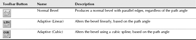
Bevel Deformation
Bevel Deformation bevels the cross-section shapes. To bevel an edge is to round the edge so it is smooth by adding more parallel edges. The Bevel Deformation window includes only one red line representing the amount of bevel applied. By default, this line is set to a 0 value. Positive values increase the bevel amount, which equals a reduction in the shape area, and negative values have the opposite effect.
You can also use the Bevel Deformation window to select three different types of beveling: Normal, Adaptive Linear, and Adaptive Cubic. Table 27.3 shows and describes the buttons for these three beveling types. You can select them from a flyout at the right end of the window.
TABLE 27.3 Bevel Deformation Buttons
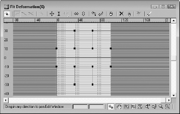
Fit Deformation
The Fit Deformation window, shown in Figure 27.21, lets you specify a profile for the outer edges of the cross-section shapes to follow. This window includes two lines: one red and one green. The red line displays the X-axis scale, and the green line displays the Y-axis scale. By default, both lines are positioned equally at the 100 percent value. Specifying a value that is greater than 100 percent increases the scale, and specifying a value less than 100 percent has the opposite effect.
Note
When using the Fit deformation, you cannot make the surface go backward on the path.
FIGURE 27.21 A Loft object with Fit Deformation applied
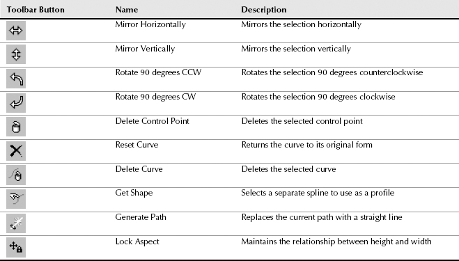
The Fit Deformation window includes ten buttons unique to it that are used to control the profile curves. These buttons are illustrated and described in Table 27.4.
TABLE 27.4 Fit Deformation Dialog Box Buttons
Modifying Loft subobjects
When you select a Loft object, you can work with its subobjects in the Modify panel. The subobjects for a Loft include Path and Shape. The Path subobject opens the Path Commands rollout. This rollout has only a single button—Put—for creating a copy of the Loft path. If you click this button, the Put To Scene dialog box appears, enabling you to give the path a name and select to create it as a Copy or an Instance.
If your path is created as an Instance, you can edit it to control the Loft path.
Tip
Scaling or transforming a cross section has no effect on the Loft because there isn't any way to access the shape transform. If you add an XForm modifier on the cross section, then you can control its transform after it is lofted.
The Shape subobject opens the Shape Commands rollout. This rollout also includes a Put button along with some additional controls. The Path Level value adjusts the shape's position on the path. The Compare button opens the Compare dialog box, which is discussed in the following section. The Reset button returns the shape to its former state before any rotation or scaling has taken place, and the Delete button deletes the shape entirely.
Note
You cannot delete a shape if it is the only shape in the Loft object.
The Shape Commands rollout also includes six Align buttons for aligning the shape to the Center, Default, Left, Right, Top, and Bottom. For the Loft object local coordinates, Left and Right move the shape along the X-axis, and Top and Bottom move it along the Y-axis.
Comparing shapes
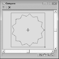
The Compare dialog box superimposes selected cross-sectional shapes included in a Loft object on top of one another to check their center alignment. The button in the upper-left corner is the Pick Shape button. This button lets you select which shapes to display in the dialog box. The button to its right is the Reset button, for removing a shape from the dialog box. Figure 27.22 shows the Compare dialog box with the two shapes from the pillar example selected. Notice that the first vertices on these two shapes are in different locations. This causes the strange twisting at both the top and bottom of the pillar.
FIGURE 27.22 You can use the Compare dialog box to align shapes included in a Loft.
Note
You can align these two vertices by subdividing the square shape in Edit Spline mode and selecting a new first vertex with the Make First button.
While the Compare dialog box is open, the Align buttons in the Shape Commands rollout are still active, and you can use them to move and position the shapes. The first vertex on each shape is shown as a small square. If these vertices aren't correctly aligned on top of one another, then the resulting Loft object will have skewed edges. The lower-right corner of the dialog box includes buttons to View Extents, Pan, Zoom, and Zoom Region.
Editing Loft paths
The original shapes that were used to create the Loft object can be edited at any time. These updates also modify the Loft object. The shapes, if not visible, can be selected using the Select by Name button. The shapes maintain their base parameters, or they can be converted to an Editable Spline.
Tutorial: Creating drapes
Modeling home interiors is a task commonly performed by professional architects and interior designers, and creating the drapes can be tricky. In this tutorial, you create some simple drapes using a Loft object.
To create drapes using a Loft object, follow these steps:
- Open the Lofted drapes.max file from the Chap 27 directory on the CD.
This file contains two splines that can be used to create the loft.
- Select the straight line spline, and select the Create Compound Loft menu command. In the Creation Method rollout, click the Get Shape button and then click the cross-section spline.
- Open the Modify panel, and under the Skin Parameters rollout, turn off the Contour and Banking options.
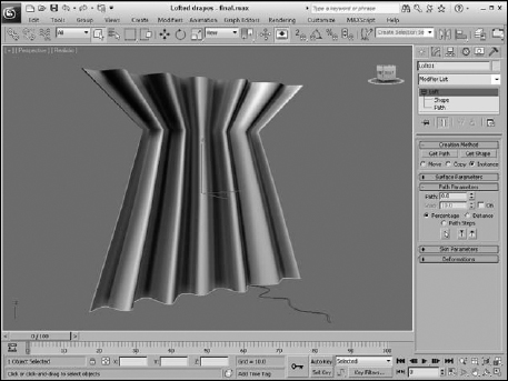
- In the Deformations rollout, click the Scale button. In the Scale Deformation dialog box that opens, use the Insert Corner Point button to create a new point at roughly 75. Switch to the Move Control Point button and drag the new point downward to create an effect such as tying them together, as shown in Figure 27.23.
FIGURE 27.23 Drapes that have been modeled using a Loft object
Loft objects versus surface tools
You can create compound Loft objects completely from 2D shape splines: One open spline is typically used as the Loft path, and other, closed splines are used as the cross sections. You can have several different cross sections, and these can change as you travel the path. Loft cross sections aren't required to have the same number of vertices, and you can modify the scale and rotation of the cross sections with the Deformation options.
See Bonus Chapter 5 on the CD, “Working with NURBS,” for more detail on the surface tools.
The surface tools, which include the CrossSection and Surface modifiers, provide another way to model that is similar to lofting. The CrossSection modifier takes several cross-section shapes and connects their vertices with additional splines to create a spline framework. You can then use the Surface modifier to cover this framework with a skin.
Although similar in nature, Loft objects and the surface tools have different subtleties and strengths.
One difference is that the CrossSection modifier connects spline cross sections according to their order. This can cause strange results if the order is incorrect. A Loft always follows a path, so the cross-section order isn't a problem.
Another difference is that surface tools give you more control over the surface of a created object. Because the underlying structure is a series of splines, you can add new branches and objects without much difficulty. This can be hard to do with Loft objects.
As a general guideline, Loft objects are better suited to modeling rigid objects with relatively uniform cross sections, whereas the surface tools are better for modeling more organic model types.
Working with ProBoolean and ProCutter Objects
The original Boolean compound object worked well enough for combining, subtracting, and intersecting objects, but it had some limitations that have been overcome with the ProBoolean and ProCutter compound objects. The original Boolean could combine only two operands together, but the ProBoolean object can perform multiple Boolean operations simultaneously. ProBoolean also can subdivide the result into quad faces. The results of the ProBoolean and ProCutter objects are much cleaner and more accurate than the original Boolean object.
The original Boolean compound object still is available for backward compatibility, but if you perform a new Boolean operation, you really should use the ProBoolean object.
Using ProBoolean
When two objects overlap, you can perform different Boolean operations on them to create a unique object. The ProBoolean operations include Union, Intersection, Subtraction, Merge, Attach, and Insert. Two additional options are available: Imprint and Cookie.
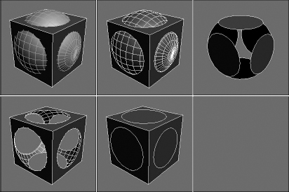
The Union operation combines two objects into one. The Intersection operation retains only the overlapping sections of two objects. The Subtraction operation subtracts the overlapping portions of one object from another. The Merge operation combines objects without removing the interior faces and adds new edges where the objects overlap. Figure 27.24 shows the original object and the first four possible Boolean operators.
Note
Unlike many CAD packages that deal with solid objects, Max's Booleans are applied to surfaces, so if the surfaces of the two objects don't overlap, all Boolean operations (except for Union) will have no effect.
FIGURE 27.24 Object before any operations and with Boolean operations: Union, Intersection, Subtraction, and Merge with the Imprint option enabled
The Attach operation combines the objects like Union but keeps them as separate elements of the same compound object. For example, if you were to look inside a compound object created with Union, you would not see the interior polygons of the combined object, but with Attach, the interior polygons would still be there.
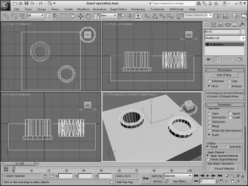
The Insert operation subtracts the second object from the first and then combines the two objects into one. If the subtracted volume makes a dent or hole into the first object, then that hole remains after the two are combined, but if the second surface has access to the first object through a hole, then the first surface covers the subtracted volume. In Figure 27.25, two tube objects have been overlapped with a box object. The left tube is capped at the bottom, forming a closed volume, but the right tube is open at the bottom. When made into a ProBoolean object with the Insert operations, the closed volume is subtracted, but the open volume is not.
The Cookie option causes the operation to cut the original object without adding any of the faces from the picked object to the original object. The Imprint option causes the outline of the operation to appear on the original object.
All Boolean operations are added in the order in which they are applied to a list in the Parameters rollout. You can select any of the operations in the list at any time and change the operation. For example, if you select the Subtraction operation from the list and then change the operation type to Union and click the Change Operation button, the Subtraction changes to a Union. With an operation selected in the list, the Extract Selected button restores the original object. When using this button, you can choose to Remove, Copy, or Instance the operation.
The order in which the operations are applied affects the result. You can reorder the operations in the list by selecting an operation, choosing its position in the list, and clicking the Reorder Ops button.
FIGURE 27.25 The Insert operation only maintains closed volumes when subtracted.
Cross-Reference
You also can apply Boolean operations to shapes using the Boolean operators available for Editable Meshes in the Geometry rollout. Chapter 12, “Drawing and Editing 2D Splines and Shapes,” covers these 2D Boolean operators.
The materials that get applied to a ProBoolean result can be set to use the Operand Material or to retain the Original Material. If you use the Operand Material with the subtraction operation, then the surface that touches the picked object retains the removed object's material, and the rest of the object has the original object's material. If the Retain Original Material option is selected, then the entire result gets the original object's material.
In the Advanced Options rollout are options for updating the scene and for reducing the complexity of the object. The Decimation value is the percentage of edges to remove from the result. If you plan on smoothing the object or converting it to an Editable Poly object, then you want to enable the Make Quadrilaterals option, which causes the polygon reduction to avoid triangles in favor of quads. You also can set the Quad Size, and you can select how planar edges are handled.
Note
If you plan to deform the mesh as part of a skinned object or a cloth simulation, the resulting mesh has to be clean or the deformation will have problems.
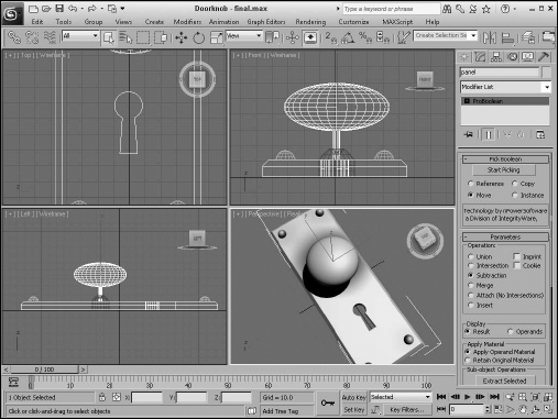
Tutorial: Creating a keyhole
What was it that Alice saw when she looked through the keyhole? The ProBoolean feature is the perfect tool for cutting a keyhole through a doorknob plate.
To use the ProBoolean object to create a keyhole, follow these steps:
- Open the Doorknob.max file from the Chap 27 directory on the CD.
- Select the doorknob plate object positioned where the keyhole is, and choose the Create Compound ProBoolean menu command. In the Parameters rollout, select the Subtraction option.
- In the Pick Boolean rollout, click the Start Picking button and select the Box and Cylinder objects positioned where the keyhole should be.
Figure 27.26 shows the finished keyhole.
FIGURE 27.26 A keyhole built using the ProBoolean object
Using ProCutter
The original Boolean compound object included a Cut option. This feature has been replaced with ProCutter, which offers many more features than the original option. ProCutter allows you to cut a single object (known as the Stock object) with multiple cutter objects.
You can pick both the Stock and Cutter objects using the buttons found in the Cutter Picking Parameters rollout. You have four options with each selection: Reference, Move, Copy, or Instance. The Auto Extract Mesh option automatically replaces the selected stock object with the extracted result. The Explode by Elements option works only when the Auto Extract Mesh option is enabled. It separates each cut element into an object.
Within the Cutter Parameters rollout, you can select from three Cutting Options. The Stock Outside Cutter option keeps the portion of the stock object that is on the outside of the cutter. The Stock Inside Cutter option is the opposite, keeping the stock portion inside the cutters. The Cutters Outside Stock option maintains those portions of the cutters that are outside of the stock.
All selected cutters and stock objects are added to a list in the Cutter Parameters. Using the Extract Selected button, you can restore any cutter or stock object that has been operated on as a Copy or Instance. Materials and Decimation also work the same as for ProBoolean objects.
Tip
The ProCutter features are helpful for dividing an object that will be animated exploding into pieces.
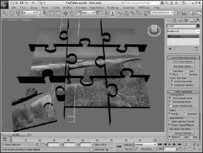
Tutorial: Creating a jigsaw puzzle
The ProCutter is useful for creating destructive scenes such as shattering glass to pieces and breaking down buildings, but it also can be used for constructive cutting such as creating a jigsaw puzzle.
To use the ProCutter compound object to divide an object into a jigsaw puzzle, follow these steps:
- Open the ProCutter puzzle.max file from the Chap 27 directory on the CD. This file includes a simple box mapped with a scenic image and several extruded lines that mark the jigsaw puzzle's edges.
- Select one of the extruded lines that mark where the cuts should be (known as a cutter), and choose the Create Compound ProCutter menu command.
- Then click the Pick Cutter Objects button and select all of the remaining cutter objects. In the Cutter Parameters rollout, enable the Stock Outside Cutter along with the Stock Inside Cutter options. Select the Retain Original Material option also.
- In the Cutter Picking Parameters rollout, enable the Auto Extract Mesh and Explode By Elements options; then select the Pick Stock Objects button and choose the Box object in the viewport.
- Open the Material Editor and drag the image material onto each puzzle piece.
Note
If you don't want to see the cutter lines, you can select and hide them.
Figure 27.27 shows the final puzzle with one piece moved away from the others.
FIGURE 27.27 A puzzle cut using the ProCutter compound object
Summary
Compound objects add several additional modeling types to your bulging modeling toolkit. From morph objects to complex deformed lofts, you can use these special-purpose types to model many different objects. This chapter covered these topics:
- The various compound object types
- Morphing objects with the same number of vertices
- Creating a Conform object with differing numbers of vertices
- Using splines and mesh objects to create a ShapeMerge object
- Creating a Terrain object using splines
- The Mesher object
- Using the BlobMesh object to simulate water
- Creating a Scatter object
- Creating a Connect object to join two objects
- Creating a Loft object
- How to control Loft parameters
- Using Loft deformations
- Modifying Loft subobjects
- Comparing the strengths of Loft objects versus surface tools
- Modeling with the ProBoolean and ProCutter objects
Max generally uses polygons and meshes as its default modeling type, but CAD packages generally work with solids. The Body Object is the answer for working between solids and meshes, and it is covered next.