
CHAPTER 25
Building Complex Scenes with Containers, XRefs, and the Schematic View
Working with containers
Externally referencing objects and scenes
Setting up an asset management system
Understanding Autodesk's vault system
Working with the Schematic View window
Working with hierarchies
Setting Schematic View preferences
Using List Views
Using containers and external references (XRefs), you can pull multiple scenes, objects, materials, and controllers together into a single scene. Both of these features allow a diverse team to work on separate parts of a scene at the same time. They also provide a great way to reuse existing resources.
A valuable tool for selecting, linking, and organizing scene objects is the Schematic View window. This window offers a 1,000-foot view of the objects in your scene. From this whole scene perspective, you can find the exact item you seek.
The Schematic View window shows all objects as simple nodes and uses arrows to show relationships between objects. This structure makes the Schematic View window the easiest place to establish links and to wire parameters. You also can use this view to quickly see all the instances of an object.
Working with Containers
Containers provide a great way to group several objects together, but containers have several additional features that extend beyond simply grouping objects together. For example, a container can be saved as an external file, which makes them easy to reuse in other scenes. Containers also can be unloaded from a scene to make the rest of the scene load quicker and to improve performance. Containers also can be locked, and the creator can set edit permissions for others.
Creating and filling containers
Containers are created using the Create ![]() Helpers
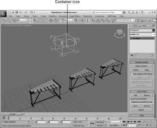
Helpers ![]() Container menu and dragging in the scene to create the Container icon, which looks like an open box, as shown in Figure 25.1. When a container is created, it is initially empty, but you can easily add objects to the container by clicking the Add button in the Local Content rollout of the Modify panel. This opens an Object Selection list where you can choose the objects to add to the container.
Container menu and dragging in the scene to create the Container icon, which looks like an open box, as shown in Figure 25.1. When a container is created, it is initially empty, but you can easily add objects to the container by clicking the Add button in the Local Content rollout of the Modify panel. This opens an Object Selection list where you can choose the objects to add to the container.
FIGURE 25.1 Containers are displayed as simple open boxes.
You can also create a container and automatically add the selected objects using the Tools ![]() Container
Container ![]() Create Container from Selection menu command. Container objects can be removed using the Remove button, which also opens an Object Selection list.
Create Container from Selection menu command. Container objects can be removed using the Remove button, which also opens an Object Selection list.
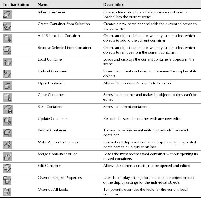
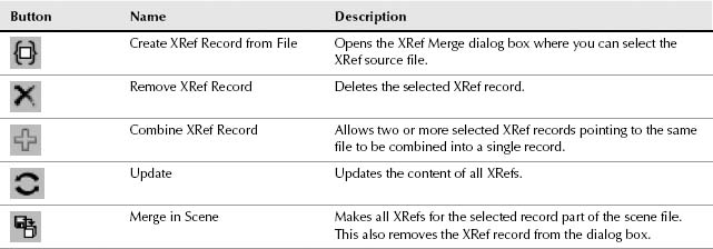
Another way to add and remove contents from a container is with the Containers toolbar, shown in Figure 25.2. You can access this toolbar by selecting it from the pop-up menu that appears by right-clicking the main toolbar away from the buttons. The Containers toolbar buttons are described in Table 25.1.
Note
These same commands for working with containers are available in the Tools ![]() Containers menu.
Containers menu.
FIGURE 25.2 The Containers toolbar
TABLE 25.1 Containers Toolbar Buttons
The various container commands can be accessed from within the Scene Explorer by enabling the Containers toolbar.
When a container is created, you can move, rotate, scale, and change the display properties of all the objects contained within the container by simply selecting the container icon first.
Closing and saving containers
When a container is first created, it is open by default. The icon for an open container displays an open box. When you select the command to close a container, then the icon changes to display a closed box. The first time this happens, a file dialog box opens, where you can save and name the container. Max container files are saved using the .maxc file extension.
Note
Within the file dialog box, you can use the Save as Type drop-down list to save the container as a Max 2012 Container or as a Max 2010 Container.
Closed containers cannot be edited by anyone except their creator. Closing a container also causes its objects to be removed from the scene, but their display is still visible because the objects are referenced from the saved file.
Updating and reloading containers
When a container is loaded into a scene from a saved container file using the Inherit Content button, it is inherited into the current scene. The inherited file maintains a link to the original container, and if the original container is edited, you can use the Update button to get the most recently saved changes.
If the container is open and allows edits, the Edit in Place button may be clicked to allow the current user to make edits to the container contents. This locks the container from all other users while the Edit in Place button is enabled. Once released, the edits are saved and made available for other users.
If you make edits that you'd like to ignore, you can use the Reload command to throw away any changes that have occurred since the last save. You also can break the link to the container with the Make All Content Unique button.
Setting container rules
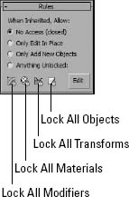
Before a container is closed, you can set rules for defining exactly what content can be edited by other users. These rules are found in the Rules rollout, shown in Figure 25.3. The options include No Access, which is applied when a container is closed; Only Edit in Place, which gives anyone that opens the container full rights to edit the container's contents; Only Add New Objects, which gives the user that opens the container the right to add new objects to the container, but not to edit any of the existing content; and Anything Unlocked, which gives the user that opens the container access to edit anything that is unlocked. Using the four toggle buttons at the bottom of the Rules rollout, you can select to lock all modifiers, materials, transforms, and objects. Clicking the Edit button opens the Track View where you can choose tracks to lock.
FIGURE 25.3 The Rules rollout lets you define precisely what in the container can be edited.
Using container proxies
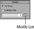
As an alternative to unloading a container from memory, you can specify a proxy container to take the place of the current container with the Proxies rollout, shown in Figure 25.4. The drop-down list can hold multiple proxy containers, allowing you to quickly change between different resolutions. Click the Modify List button to add proxy containers to the list.
FIGURE 25.4 The Proxies rollout lets you substitute proxy containers for the current one.
Setting global container preferences
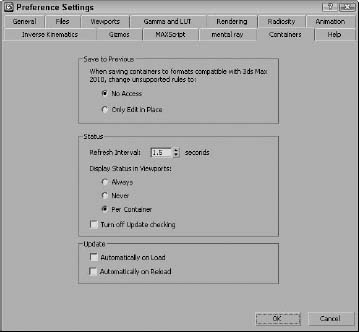
Within the Preference Settings dialog box is a panel for setting the global container preferences, shown in Figure 25.5. Using these settings you can define which rules are used when saving to the Max 2010 container format. You also can set how often containers are refreshed and whether to display the status of the scene containers.
FIGURE 25.5 The Containers panel of the Preference Settings dialog box holds the global container settings.
Referencing External Objects
No man is an island, and if Autodesk has its way, no Max user will be an island, either. XRefs (which stands for eXternal References) make it easy for creative teams to collaborate on a project without having to wait for another group member to finish his or her respective production task. External references are objects and scenes contained in separate Max files and made available for reference during a Max session. This arrangement enables several artists on a team to work on separate sections of a project without interfering with one another or altering each other's work.
Max includes two different types of XRefs: XRef scenes and XRef objects. You also can use XRef for materials, modifiers, and controllers.
Note
Although XRefs are helpful and maintained for backward compatibility, in many ways using containers is the preferred method for loading in external files.
Using XRef scenes
An externally referenced scene is one that appears in the current Max session, but that is not accessible for editing or changing. The scene can be positioned and transformed when linked to a parent object and can be set to update automatically as changes are made to the source file.
As an example of how XRef scenes facilitate a project, let's say that a design team is in the midst of creating an environment for a project while the animator is animating a character model. The animator can access the in-production environment as an XRef scene in order to help him move the character correctly about the environment. The design team members are happy because the animator didn't modify any of their lights, terrain models, maps, and props. The animator is happy because he won't have to wait for the design team members to finish all their tweaking before he can get started. The end result is one large, happy production team (if they can meet their deadlines).
Choose Application Button ![]() References
References ![]() XRef Scenes to open the XRef Scenes dialog box, shown in Figure 25.6, which you use to load XRef scenes into a file.
XRef Scenes to open the XRef Scenes dialog box, shown in Figure 25.6, which you use to load XRef scenes into a file.
FIGURE 25.6 The XRef Scenes dialog box lets you specify which scenes to load as external references.

XRef scene options
In the XRef Scenes dialog box are several options for controlling the appearance of the scene objects, how often the scene is updated, and to which object the scene is bound. This dialog box is modeless, and you can open and change the options in this dialog box at any time.
The pane on the left lists all XRef scenes in the current scene. These scenes are displayed using their full path unless the Convert Local File Paths to Relative option in the Files panel of the Preference Settings dialog box is enabled. To the right are the settings, which can be different for each XRef scene in the list. To view or apply a setting, you first need to select the scene from the list. You can remove any scene by selecting it from the list and clicking the Remove button.
If an XRef scene in the list is displayed in red, then the scene could not be loaded. If the path or name is incorrect, you can change it in the Path field at the bottom of the list.
The Convert Selected button converts any selected objects in the current scene to XRef objects by saving them as a separate file. This button opens a dialog box to let you name and save the new file. If no objects are selected in the current scene, then this option is disabled.
Use the Enabled option to enable or disable all XRef scenes. Disabled scenes are displayed in gray. The Merge button lets you insert the current XRef scene into the current scene. This button removes the scene from the list and acts the same way as the Application Button ![]() Import
Import ![]() Merge command.
Merge command.
Updating an external scene
Automatic is a key option that can set any XRef scene to be automatically updated. Enable this option by selecting a scene from the list and checking the Automatic option box; thereafter, the scene is updated anytime the source file is updated. This option can slow the system if the external scene is updated frequently, but the benefit is that you can work with the latest update.
The Update Now button is for manually updating the XRef scene. Click this button to update the external scene to the latest saved version.
External scene appearance
Other options let you decide how the scene is displayed in the viewports. You can choose to make the external scene invisible or to display it as a box. Making an external scene invisible removes it from the viewports, but the scene is still included in the rendered output. To remove a scene from the rendered output, deselect the Enabled option.
The Ignore section lists objects such as lights, cameras, shapes, helpers, and animation; selecting them causes them to be ignored and to have no effect in the scene. If an external scene's animation is ignored, then the scene appears as it does in frame 0.
Positioning an external scene
Positioning an external scene is accomplished by binding the scene to an object in the current scene (a dummy object, for example). The XRef Scenes dialog box is modeless, so you can select the object to bind to without closing the dialog box. After a binding object is selected, the external scene transforms to the binding object's pivot point. The name of the parent object is also displayed in the XRef Scenes dialog box.
Transforming the object to which the scene is bound can control how the external scene is repositioned. To unbind an object, click the Unbind button in the XRef Scenes dialog box. Unbound scenes are positioned at the World origin for the current scene.
Specifying an XRef as an overlay
The Overlay option in the XRef Scenes dialog box makes the XRef visible to the current scene, but not to any other scenes that XRef the scene including the overlay. This provides a way to hide XRef content from more than one level. Overlay XRefs also make it possible to avoid circular dependencies. For example, in previous Max versions, Max wouldn't allow two designers to XRef one another's scenes, but if one of the scenes is an overlay, then this can be done.
Working with XRef scenes
You can't edit XRef scenes in the current scene. Their objects are not visible in the Select by Name dialog box or in the Track and Schematic Views. You also cannot access the Modifier Stack of external scenes’ objects. However, you can make use of external scene objects in other ways. For example, you can change a viewport to show the view from any camera or light in the external scene. External scene objects are included in the Summary Info dialog box.
Tip
Another way to use XRef scenes is to create a scene with lights and/or cameras positioned at regular intervals around the scene. You can then use the XRef Scenes dialog box to turn these lights on and off or to select from a number of different views without creating new cameras.
You also can nest XRef scenes within each other, so you can have one XRef scene for the distant mountains that includes another XRef for a castle.
Note
If a Max file is loaded with XRef files that cannot be located, a warning dialog box appears, enabling you to browse to the file's new location. If you click OK or Cancel, the scene still loads, but the external scenes are missing.
Tutorial: Adding an XRef scene
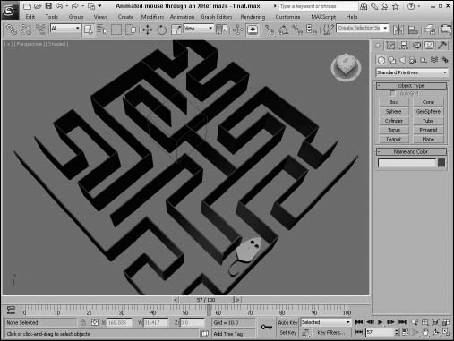
As an example of a project that would benefit from XRefs, I've created a maze environment. I open a new Max file and animate a simple mouse moving through this maze that is opened as an XRef scene.
To set up an XRef scene, follow these steps:
- Create a new Max file by choosing Application Button
 New.
New. - Choose Application Button References XRef Scenes to open the XRef Scenes dialog box.
- Click the Add button, locate the Maze.max file from the Chap 25 directory on the CD, and click Open to add it to the XRef Scene dialog box list, but don't close the dialog box just yet.
Tip
You can add several XRef scenes by clicking the Add button again. You also can add a scene to the XRef Scene dialog box by dragging a .max file from Windows Explorer or from the Asset Manager window.
- Select Create Helpers Dummy, and drag in the Perspective viewport to create a new Dummy object.
- In the XRef Scenes dialog box, click the Bind button and select the dummy object.
This enables you to reposition the XRef scene as needed.
- Select the Automatic update option, and then click Close to exit the XRef Scene dialog box.
- Now animate objects moving through the maze.
Figure 25.7 shows the Maze.max scene included in the current Max file as an XRef.
Tip
With the simple mouse animated, you can replace it at a later time with a detailed model of a furry mouse using the Application Button ![]() Import
Import ![]() Replace command.
Replace command.
FIGURE 25.7 The maze.max file loaded into the current file as an XRef scene
Using XRef objects
XRef objects are slightly different from XRef scenes. XRef objects appear in a scene and can be transformed and animated, but the original object's structure and Modifier Stack cannot be changed.
An innovative way to use this feature would be to create a library of objects that you could load on the fly as needed. For example, if you had a furniture library, you could load several different styles until you got just the look you wanted.
You also can use XRef objects to load low-resolution proxies of complex models in order to lighten the system load during a Max session. This method increases the viewport refresh rate.
Many of the options in the XRef Objects dialog box, shown in Figure 25.8, are the same as in the XRef Scenes dialog box.
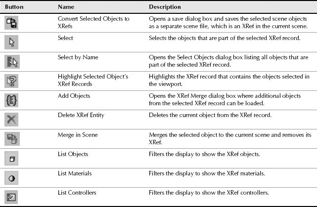
The interface buttons for the XRef Objects dialog box are listed in Table 25.2.
FIGURE 25.8 The XRef Objects dialog box lets you choose which files to look in for external objects.

TABLE 25.2 XRef Objects Dialog Box
The XRef Objects dialog box is divided into two sections. The top section displays the externally referenced source files (or records), and the lower section displays the objects, materials, or controllers selected from the source file. If multiple files are referenced, then a file needs to be selected in the top pane in order for its objects and materials to be displayed in the lower pane.
The Convert Selected button works the same as in the XRef Scenes dialog box. It enables you to save the selected objects in the current scene to a separate file just like the Application Button ![]() Save As
Save As ![]() Save Selected command and to have them instantly made into XRefs.
Save Selected command and to have them instantly made into XRefs.
In the XRef Objects dialog box, you can choose to automatically update the external referenced objects or use the Update button or you can enable the Automatic Update option. You also can enable or disable all objects in a file with the Enabled option. The Include All option skips the XRef Merge dialog box and automatically includes all objects in the source file.
If the Merge Transforms, Merge Materials, and Merge Manipulators options are enabled before an XRef file is added, all transforms, materials, and manipulators are automatically combined with the current scene instead of being referenced. When merged, the link between the source file is broken so that changes to the source file aren't propagated.
Using material XRefs
When a source file is loaded into the XRef Objects dialog box, both its objects and materials are loaded and included. If the Merge Materials option is selected before the source file is loaded, then the materials are included with the objects, but if the Merge Materials option isn't enabled, then the objects and the materials appear as separate entities. You can use the List Objects and the List Materials buttons to list just one type of entity.
Materials also can be referenced from directly within the Material Editor. If you used a material in a previous scene that would be perfect in your current scene, you can just select the XRef Material from the Material/Map Browser. This material type includes fields where you can browse to an external scene file and select a specific object. The selected material is added automatically to the XRef Objects dialog box.
Cross-Reference
You can learn more about applying materials and using the Material Editor in Chapter 15, “Using the Slate Material Editor.”
Merging modifiers
If the Merge Manipulators option is enabled before loading the XRef file, then any manipulator that is part of the XRef object is merged and loaded along with the object. You also can specify how modifiers are included with XRef objects, but you must select the option from the Modifier drop-down list before the file is selected. The XRef option loads all modifiers with the XRef object, but hides them from being edited. New modifiers can be added to the object. The Merge option adds all modifiers to the XRef object and makes these modifiers accessible via the Modifier Stack. The Ignore option strips all modifiers from the XRef object.
XRef objects appear and act like any other object in the scene. You may see a slight difference if you open the Modifier Stack. The Stack displays “XRef Object” as its only entry.
Using proxies
When an XRef object is selected in the viewport, all details concerning the XRef object—including its source filename, Object Name, and status—are listed in the Modify panel. The Modify panel also includes a Proxy Object rollout, where you can select a separate object in a separate file as a proxy object. The File or Object Name buttons open a file dialog box where you can select a low-resolution proxy object in place of a more complex object. This feature saves memory by not requiring the more complex object to be kept in memory. You also can select to enable or disable the proxy or use the proxy in rendering.
Tip
The real benefit of using proxies is to replace complex referenced objects with simpler objects that update quickly. When creating a complex object, remember to also create a low-resolution version to use as a proxy.
Controller XRefs
In addition to objects, materials, and modifiers, controllers also can be externally referenced. This means that you can borrow the controller motions of an object in a separate scene and save some animation time. To reference an external controller, select the Transform track and choose the XRef Controller option. This opens a File dialog box followed by a Select Object dialog box where you can choose with the controller the object that you want to reference. XRef controllers also appear as records in the XRef Objects dialog box.
You can learn more about applying and using controllers in Chapter 22, “Animating with Constraints and Simple Controllers.”
Configuring XRef paths
The Configure Paths dialog box includes an XRefs tab for setting the paths for XRef scenes and objects, shown in Figure 25.9. Choose Customize ![]() Configure User Paths to open the XRefs panel.
Configure User Paths to open the XRefs panel.
FIGURE 25.9 The XRefs panel in the Configure User Paths dialog box lets you specify paths to be searched when an XRef cannot be located.
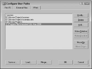
Max keeps track of the path of any XRefs used in a scene, but if it cannot find them, it looks at the paths designated in the XRefs panel of the Configure Paths dialog box. For projects that use lots of XRefs, populating this list with potential paths is a good idea. Paths are scanned in the order they are listed, so place the most likely paths at the top of the list.
To add a new path to the panel, click the Add button. You also can modify or delete paths in this panel with the Modify and Delete buttons.
Using the Schematic View Window
A great way to organize and select objects is to use the Schematic View window. Every object in the Schematic View is displayed as a labeled rectangular box. These boxes (or nodes) are connected to show the relationships among them. You can rearrange them and save the customized views for later access.
![]() You access the Schematic View window via the Graph Editors menu command or by clicking its button on the main toolbar. When the window opens, it floats on top of the Max interface and can be moved by dragging its title bar. You also can resize the window by dragging on its borders. The window is modeless and lets you access the viewports and buttons in the interface beneath it.
You access the Schematic View window via the Graph Editors menu command or by clicking its button on the main toolbar. When the window opens, it floats on top of the Max interface and can be moved by dragging its title bar. You also can resize the window by dragging on its borders. The window is modeless and lets you access the viewports and buttons in the interface beneath it.
The Graph Editors menu options
The Schematic View menu options enable you to manage several different views. The Graph Editors ![]() New Schematic View command opens the Schematic View window, shown in Figure 25.10. If you enter a name in the View Name field at the top of the window, you can name and save the current view. This name then appears in the Graph Editors
New Schematic View command opens the Schematic View window, shown in Figure 25.10. If you enter a name in the View Name field at the top of the window, you can name and save the current view. This name then appears in the Graph Editors ![]() Saved Schematic Views submenu and also in the title bar when the saved view is open.
Saved Schematic Views submenu and also in the title bar when the saved view is open.
Every time the Graph Editors ![]() New Schematic View menu command is used, a new view name is created and another view is added to the Saved Schematic Views submenu. The Schematic View
New Schematic View menu command is used, a new view name is created and another view is added to the Saved Schematic Views submenu. The Schematic View ![]() Delete Schematic View command opens a dialog box in which you can select the view you want to delete.
Delete Schematic View command opens a dialog box in which you can select the view you want to delete.
Tip
You can open any saved Schematic View window (or a new Schematic View window) within a viewport by right-clicking the viewport title, choosing Views ![]() Schematic, and clicking the view name in the pop-up menu.
Schematic, and clicking the view name in the pop-up menu.
FIGURE 25.10 The Schematic View window displays all objects as nodes.
The Schematic View interface
The Schematic View window includes several common interface elements, including menus, toolbar buttons, and a right-click quadmenu. Just like the main interface, you can access the commands in many ways.
Using the Schematic View menus
The Schematic View window includes menus at the top of its interface, including Edit, Select, List Views, Layout, Options, Display, and View.
The Edit menu includes commands to Connect (C) and Unlink Selected object nodes. It also includes a Delete command, which deletes an object from the viewports as well as from the object node. The Edit menu includes commands to Assign Controllers, Wire Parameters, and open the Object Properties dialog box.
Many of the keyboard shortcuts for the Schematic View window are the same as those in the main interface. If you enable the Keyboard Shortcut Override Toggle, you can use the Schematic View keyboard shortcuts.
The Select menu includes commands for accessing the Select tool (S or Q); selecting All (Ctrl+A), None (Ctrl+D), and Invert (Ctrl+I); selecting (Ctrl+C) and deselecting children; and commands to sync the selected nodes in the Schematic View with the scene (Select from Scene) and vice versa (Select to Scene).
The List Views menu determines what is shown in the Schematic View. Options include All Relationships, Selected Relationships, All Instances, Selected Instances, Show Occurrences, and All Animated Controllers. Many of these options are available in the Display Floater as well.
The Layout menu includes various options for controlling how the nodes are arranged. The Align submenu lets you align selected nodes to the Left, Right, Top, Bottom, Center Horizontal, or Center Vertical. You can also Arrange Children or Arrange Selected. The Free Selected (Alt+S) and Free All (Alt+F) commands keep nodes from being auto arranged. With the Layout menu, you also can Shrink Selected, Unshrink Selected, Unshrink All, and Toggle Shrink (Ctrl+S).
The Options menu lets you select the Always Arrange option and view mode (either Hierarchy or Reference mode). You also can select the Move Children (Alt+C) option and open the Schematic View Preferences (P) dialog box.
The Display menu provides access to the Display Floater. The Display Floater (D) command opens the Display floater, which can be used to select the types of nodes to display. You also can hide and unhide nodes and expand or collapse the selected node.
The View menu includes commands for selecting the Pan (Ctrl+P), Zoom (Alt+Z), and Zoom Region (Ctrl+W) tools. You also can access the Zoom Extents (Alt+Ctrl+Z), Zoom Extents Selected (Z), and Pan to Selected commands. The View menu also includes options to Show/Hide Grid (G), Show/Hide Background, and Refresh View (Ctrl+U).
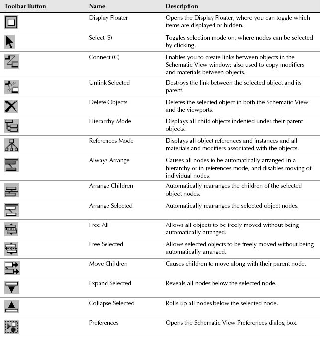
Learning the toolbar buttons
You can select most of these commands from the toolbar. Many of the toolbar buttons are toggle switches that enable and disable certain viewing modes. The background of these toggle buttons is highlighted yellow when selected. You'll also find some buttons along the bottom of the window. All Schematic View icon buttons are shown in Table 25.3 and are described in the following sections.
Note
The Schematic View toolbar buttons are permanently docked to the interface and cannot be removed.
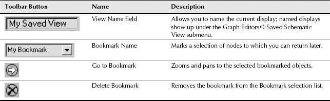
As you navigate the Schematic View window, you can save specific views as bookmarks by typing an identifying name in the Bookmark drop-down list. To recall these views later, select them from the drop-down list and click the Go to Bookmark icon in the Schematic View toolbar. Bookmarks can be deleted with the Delete Bookmark button.
Note
Most of the menu commands and toolbar buttons are available in a pop-up menu that you can access by right-clicking in the Schematic View window.
TABLE 25.3 Schematic View Toolbar Buttons
Navigating the Schematic View window
As the number of nodes increases, it can become tricky to locate and see the correct node to work with. Along the bottom edge of the Schematic View window are several navigation buttons that work similarly to the Viewport Navigation Control buttons. Using these buttons, you can pan, zoom, and zoom to the extents of all nodes. These buttons are described in Table 25.4.
TABLE 25.4 Schematic View Navigation Buttons
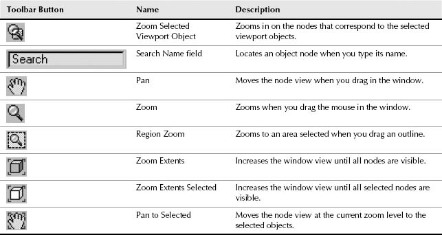
The Schematic View navigation buttons also can be accessed from within the View menu. These menu commands include Pan Tool (Ctrl+P), Zoom Tool (Alt+Z), Zoom Region tool (Ctrl+W), Zoom Extents (Alt+Ctrl+Z), Zoom Extents Selected (Z), and Pan to Selected.
Tip
You also can navigate the Schematic View window using the mouse and its scroll wheel. Scrubbing the mouse wheel zooms in and out of the window in steps. Holding down the Ctrl key and dragging with the scroll wheel button zooms smoothly in and out of the window. Dragging the scroll wheel pans within the window.
Working with Schematic View nodes
Every object displayed in the scene has a node—a simple rectangular box that represents the object or attribute. Each node contains a label, and the color of the node depends on the node type.
Node colors
Nodes have a color scheme to help identify them. The colors of various nodes are listed in Table 25.5.
TABLE 25.5 Schematic View Node Colors
| Color | Name |
| White | Selected node |
| Blue | Geometry Object node |
| Cyan | Shape Object node |
| Yellow | Light Object node |
| Dark Blue | Camera Object node |
| Green | Helper Object node |
| Purple | Space Warp Object node |
| Goldenrod | Modifier node |
| Dark Yellow | Base Object node |
| Brown | Material node |
| Dark Green | Map node |
| Salmon | Controller node |
| Magenta | Parameter Wires |
Note
If you don't like any of these colors, you can set the colors used in the Schematic View using the Colors panel of the Customize ![]() Customize User Interface dialog box.
Customize User Interface dialog box.
Selecting nodes
When you click the Select (S) button, you enter select mode, which lets you select nodes within the Schematic View window by clicking the object node. You can select multiple objects by dragging an outline over them. Holding down the Ctrl key while clicking an object node selects or deselects it. Selected nodes are shown in white.
The Select menu includes several selection commands that enable you to quickly select (or deselect) many nodes, including Select All (Ctrl+A), Select None (Ctrl+D), Select Invert (Ctlr+I), Select Children (Ctrl+C), and Deselect Children.
If the Select ![]() Sync Selection option in the Select menu is enabled, then the node of any object that is selected in the viewports is also selected in the Schematic View window, and vice versa. If you disable the Sync Selection option, you can select different objects in the viewports and in the Schematic View at the same time. The node of the object selected in the viewports is outlined in white, and the interior of selected nodes is white. To select all the objects in the viewports that match the selected nodes without the Sync Selection option enabled, just use Select
Sync Selection option in the Select menu is enabled, then the node of any object that is selected in the viewports is also selected in the Schematic View window, and vice versa. If you disable the Sync Selection option, you can select different objects in the viewports and in the Schematic View at the same time. The node of the object selected in the viewports is outlined in white, and the interior of selected nodes is white. To select all the objects in the viewports that match the selected nodes without the Sync Selection option enabled, just use Select ![]() Select to Scene.
Select to Scene.
Tip
All animated objects have their node border drawn in red.
Rearranging nodes
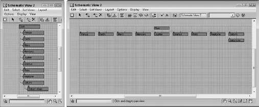
The Schematic View includes several options for arranging nodes. In the Options menu, you can toggle between Hierarchy and Reference modes. Hierarchy mode displays the nodes vertically with child objects indented under their parent. Reference mode displays the nodes horizontally, allowing for plenty of room to display all the various reference nodes under each parent node. Figure 25.11 shows these modes side by side.
FIGURE 25.11 The Schematic View window can automatically arrange nodes in two different modes: Hierarchy and Reference.
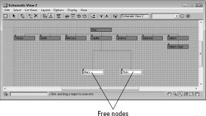
You can move nodes and rearrange them in any order. To move a node, simply click and drag it to a new location. When a node is dragged, all selected nodes move together, and any links follow the node movement. If a child node is moved, all remaining child nodes collapse together to maintain the specified arrangement mode. The moved node then becomes free, which is designated by an open rectangle on the left edge of the node. Figure 25.12 shows two nodes that were moved and thereby became free. The other children automatically moved closer together to close the gaps made by the moving nodes.
FIGURE 25.12 Free nodes are moved independent of the arranging mode.
Using the Layout ![]() Free Selected (Alt+S) and Free All (Alt+F) menu commands, you can free the selected nodes or all nodes. You also can auto arrange all the children of a node with the Layout
Free Selected (Alt+S) and Free All (Alt+F) menu commands, you can free the selected nodes or all nodes. You also can auto arrange all the children of a node with the Layout ![]() Arrange Children menu command or arrange just the selected nodes (Layout
Arrange Children menu command or arrange just the selected nodes (Layout ![]() Arrange Selected). The Options
Arrange Selected). The Options ![]() Move Children (Alt+C) command causes all children to be moved along with their parent when the parent is moved. This causes free and non-free nodes to move with their parent.
Move Children (Alt+C) command causes all children to be moved along with their parent when the parent is moved. This causes free and non-free nodes to move with their parent.
If the Options ![]() Always Arrange option is enabled, Max automatically arranges all the nodes using either the Hierarchy mode or Reference mode, but you cannot move any of the nodes while this option is enabled. If you move any nodes when the Always Arrange option is selected, a dialog box appears telling you that your custom layout will be lost. If the Always Arrange option is enabled, the Arrange Children, Free All (Alt+F), Free Selected (Alt+S), Move Children (Alt+C), and all the Align options are all disabled. If two or more nodes are selected, you can align them using the Layout
Always Arrange option is enabled, Max automatically arranges all the nodes using either the Hierarchy mode or Reference mode, but you cannot move any of the nodes while this option is enabled. If you move any nodes when the Always Arrange option is selected, a dialog box appears telling you that your custom layout will be lost. If the Always Arrange option is enabled, the Arrange Children, Free All (Alt+F), Free Selected (Alt+S), Move Children (Alt+C), and all the Align options are all disabled. If two or more nodes are selected, you can align them using the Layout ![]() Align menu. The options include Left, Right, Top, Bottom, Center Horizontal, and Center Vertical.
Align menu. The options include Left, Right, Top, Bottom, Center Horizontal, and Center Vertical.
Hiding, shrinking, and deleting nodes
If your Schematic View window starts to get cluttered, you can always hide nodes to simplify the view. To hide a node, select the nodes to hide and use the Display ![]() Hide Selected menu command. The Display
Hide Selected menu command. The Display ![]() Unhide All menu command can be used to make the hidden nodes visible again.
Unhide All menu command can be used to make the hidden nodes visible again.
Note
If you hide a parent object, its children nodes are hidden also.
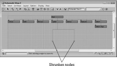
Another useful way to reduce clutter in the Schematic View window is with the Layout ![]() Shrink Selected command. This command replaces the rectangular node with a simple dot, but all hierarchical lines to the node are kept intact. Figure 25.13 shows a Schematic View with several shrunk nodes. Shrunk nodes can be unshrunk with the Layout
Shrink Selected command. This command replaces the rectangular node with a simple dot, but all hierarchical lines to the node are kept intact. Figure 25.13 shows a Schematic View with several shrunk nodes. Shrunk nodes can be unshrunk with the Layout ![]() Unshrink Selected and Unshrink All menu commands.
Unshrink Selected and Unshrink All menu commands.
Note
The Shrink commands work only when Layout ![]() Toggle Shrink (Ctrl+S) is enabled. With this command, you can turn on and turn off the visibility of shrunken nodes.
Toggle Shrink (Ctrl+S) is enabled. With this command, you can turn on and turn off the visibility of shrunken nodes.
FIGURE 25.13 Shrunken nodes appear as simple dots in the Schematic View.
To delete a node, select the node and click the Delete Objects button on the Schematic View toolbar or press the Delete key. If several nodes are selected, they are all deleted. This deletes the object in the viewports also.
Renaming objects
In the Schematic View window, you can rename objects quickly and conveniently. To rename an object, click a selected node and click again to highlight the text. When the text is highlighted, you can type the new name for the object. This works only for nodes that have a name, which includes materials.
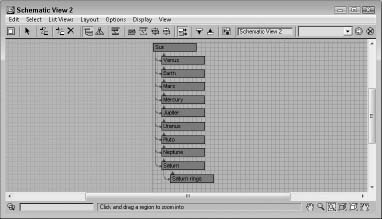
Tutorial: Rearranging the solar system
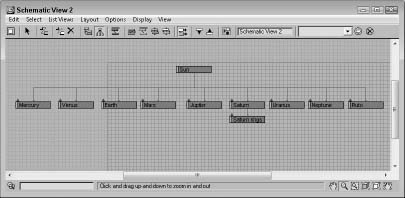
To practice moving nodes around, you'll order the solar system model. When Max places nodes in the Schematic View, it really doesn't follow any specific order, but you can move them as needed by hand.
To rearrange the solar system nodes, follow these steps:
- Open the Ordered solar system.max file from the Chap 25 directory on the CD.
This file includes several named spheres representing the solar system.
- Select Graph Editors New Schematic View to open the Schematic View window.
All planets are displayed as blue nodes under the Sun object.
- Select Options Reference Mode (if it is not already selected) to position all the nodes horizontally. Click the Select tool on the main toolbar, or press the S key.
- Make sure the Options Always Arrange option is disabled. Then click and drag the Mercury node to the left, and place it in front of the Venus node.
- Select the Options Move Children (Alt+C) menu command, and drag and drop the Saturn node between the Jupiter and Uranus nodes.
With the Move Children option enabled, the Saturn rings node moves with its parent.
- Drag and drop the Pluto node beyond the Neptune node.
- Select all the planet nodes, and choose Layout Align Top to align all the nodes together.
Note
Although astronomers no longer classify Pluto as a planet, I doubt that this book is required reading for astronomers. I think we can get away with calling Pluto a planet.
Figure 25.14 shows the rearranged hierarchy with all the planets lined up in order.
FIGURE 25.14 After rearranging nodes to the correct order, the planets are easy to locate.
Working with Hierarchies
Another key benefit of the Schematic View is to see the relationships between different objects. With the Schematic View open, you can quickly tell which objects are children and which are parents. You also can see which objects have modifiers and which have materials applied. You can get a wealth of knowledge from the Schematic View.
Using the Display floater
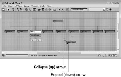
With all relationships enabled, the Schematic View becomes a mess. Luckily, you can control which Relationships and which Entities are displayed using the Display floater, shown in Figure 25.15.
FIGURE 25.15 The Display floater can turn nodes and lines on and off in the Schematic View.
The top section of the Display floater shows or hides relationships between nodes, which are displayed as lines. The relationships that you can control include Constraints, Controllers, Parameter Wires, Light Inclusion, and Modifiers. If you hold the mouse over these relationship lines, the details of the relationship are shown in the tooltip that appears.
Tip
For some relationships, you can double-click the relationship line to open a dialog box where you can edit the relationship. For example, double-clicking a Parameter Wire relationship line opens the Parameter Wiringdialog box.
The lower section of the Display floater lets you show or hide entities that are displayed as nodes, including Base Objects, Modifier Stack, Materials, and Controllers. The P, R, and S buttons let you turn on Positional, Rotational, and Scale controllers. When a node has a relationship with another node, the right end of the node displays an arrow. Clicking this arrow toggles the relationship lines on and off.
The Expand button shows the actual nodes when enabled but only an arrow that can be clicked to access the nodes if disabled. The Focus button shows all related objects as colored nodes, and all other nodes are unshaded.
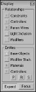
Figure 25.16 shows a Schematic View with the Base Objects and Controllers Entities selected in the Display floater. The Expand button also is disabled. This makes up and down arrows appear above each node. Clicking the up arrow collapses the node, rolling it up into its parent. Clicking the down arrow expands the node and displays the Base Object and Controller nodes for the node that you clicked, such as the Earth node in Figure 25.14. You also can expand and collapse nodes with the Display ![]() Expand Selected and Collapse Selected menu commands.
Expand Selected and Collapse Selected menu commands.
Hierarchical relationships are shown as lines that connect the nodes. Even if the nodes are moved, the lines follow as needed to show the relationship between the nodes.
FIGURE 25.16 Schematic View nodes can be collapsed or expanded by clicking the up and down arrows.
Connecting nodes
To create a hierarchy, use the Edit ![]() Connect menu command, or press the C shortcut, or click the Connect button on the Schematic View toolbar. This enters Connect mode, which lets you link objects together; copy modifiers, materials, or controllers between nodes; or even wire parameters.
Connect menu command, or press the C shortcut, or click the Connect button on the Schematic View toolbar. This enters Connect mode, which lets you link objects together; copy modifiers, materials, or controllers between nodes; or even wire parameters.
For linking nodes, the Connect button works the same way here as it does on the main toolbar—selecting the child node and dragging a line from the child node to its parent. You can even select multiple nodes and link them all at once.
The Edit ![]() Unlink Selected menu command (and toolbar button) destroys the link between any object and its immediate parent. Remember that every child object can have only one parent.
Unlink Selected menu command (and toolbar button) destroys the link between any object and its immediate parent. Remember that every child object can have only one parent.
Copying modifiers and materials between nodes
Before you can copy materials or modifiers between nodes, you need to make sure they are visible. Material nodes and modifier nodes show up only if they are enabled in the Display floater. You can access this floater by clicking the Display floater button (or by pressing the D key).
To copy a material or modifier, select the material node for one object, click the Connect (C) button, and drag the material to another object node.
Note
In the Schematic View, materials can be copied only between objects; you cannot apply new materials from the Material Editor to Schematic View nodes.
When modifiers are copied between nodes, a dialog box appears, giving you the chance to Copy, Move, or Instance the modifier. You also can use the Schematic View window to reorder the Modifier Stack. Using the Connect tool, just drag the modifier node to the modifier node that you want to be beneath and the stack is reordered.
Cross-Reference
You can learn more about applying modifiers and the Modifier Stack in Chapter 11, “Introducing Modifiers and Using the Modifier Stack.”
Assigning controllers and wiring parameters
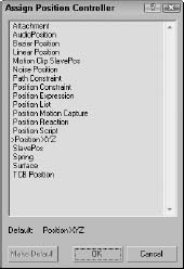
If controller nodes are visible, you can copy them to another node using the same technique used for materials and modifiers using the Connect (C) button. You also can assign a controller to an object node that doesn't have a controller using the Edit ![]() Assign Controller menu command. This opens the Assign Controller dialog box, shown in Figure 25.17, where you can select the controller to apply.
Assign Controller menu command. This opens the Assign Controller dialog box, shown in Figure 25.17, where you can select the controller to apply.
FIGURE 25.17 Controllers can be assigned using the Schematic View window.
Nodes can be wired using the Schematic View window. To wire parameters, select the node you want to wire and select Edit ![]() Wire Parameters. A pop-up menu of wire parameters appears that works the same as in the viewports. All parameter wiring relationships are shown in magenta.
Wire Parameters. A pop-up menu of wire parameters appears that works the same as in the viewports. All parameter wiring relationships are shown in magenta.
Cross-Reference
You can learn more about parameter wiring in Chapter 21, “Understanding Animation and Keyframes.”
Tutorial: Linking a character with the Schematic View
Perhaps one of the greatest benefits of the Schematic View is its ability to link objects. This can be tricky in the viewports because some objects are small and hidden behind other items. The Schematic View with its nodes that are all the same size makes it easy, but only if the objects are named correctly.
To link a character model using the Schematic View, follow these steps:
- Open the Futuristic man.max file from the Chap 25 directory on the CD.
This file includes a simplified version of a futuristic man created by Viewpoint Datalabs with no links between the various parts.
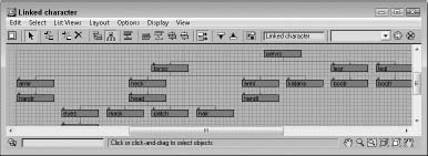
- Select Graph Editors New Schematic View to open a Schematic View window, and name the view Linked character. Click the Region Zoom button in the lower-right corner, and drag over the nodes at the left end of the Schematic View.
For this model, you want the pelvis to be the parent node.
- Click the Connect button on the toolbar (or press the C key), and drag from the handr node to the armr node to link the two nodes. Continue linking by connecting the following nodes: handl to arml, head to neck, pupil to eyes, bootr to legr, bootl to legl, and torso to pelvis.
- Select the eyes, mask, patch, and hair nodes, and drag them all to the head node.
- Finally, grab the armr, arml, neck, and katana nodes, and drag them to the torso node and the legr and legl nodes to the pelvis node.
This completes the hierarchy.
Note
Typically, when rigging characters, you want the pelvis to be the parent object because it is the center of most of the character movement.
Figure 25.18 shows the final geometry object nodes of the linked character. If you move the pelvis part in the viewports, all the parts move together.
FIGURE 25.18 All character parts are now linked to the man's pelvis part.
Setting Schematic View Preferences
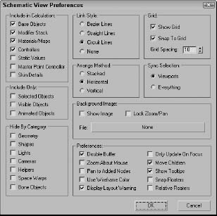
The Preferences button (or the Options ![]() Preferences command) opens the Schematic View Preferences dialog box, shown in Figure 25.19, where you can set which items are displayed or hidden, set up grids and background images, and specify how the Schematic View window looks.
Preferences command) opens the Schematic View Preferences dialog box, shown in Figure 25.19, where you can set which items are displayed or hidden, set up grids and background images, and specify how the Schematic View window looks.
FIGURE 25.19 The Schematic View Preferences dialog box lets you customize many aspects of the Schematic View window.
Limiting nodes
When the Schematic View window is opened, Max traverses the entire hierarchy looking for objects and features that can be presented as nodes. If you have a complex scene and don't intend to use the Schematic View to see materials or modifiers, you can disable them in the Include in Calculation section of the Schematic View Preferences dialog box. This provides a way to simplify the data presented. With less data, locating and manipulating what you are looking for becomes easier.
The Include in Calculation section includes options for limiting the following:
- Base Objects: The geometry type that makes up a node. The node is the named object, such as Earth; the Base Object is its primitive, such as Sphere (Object).
- Modifier Stack: Identifies all nodes with modifiers applied.
- Materials/Maps: Identifies all nodes with materials and maps applied.
- Controllers: Identifies all nodes that have controllers applied.
- Static Values: Displays unanimated parameter values.
- Master Point Controller: Displays nodes for any subobject selections that include controllers.
- Skin Details: Displays nodes for the modifiers and controllers that are used when the Skin modifier is applied to a bones system.
You also can limit the number of nodes by using the Include Only options. The Selected Objects option shows only the objects selected in the viewports. The nodes change as new objects are selected in the viewports. The Visible Objects option displays only the nodes for those objects that are not hidden in the viewports, and the Animated Objects option displays only the nodes of the objects that are animated.
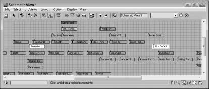
Object categories that can be hidden include Geometry, Shapes, Lights, Cameras, Helpers, Space Warps, and Bone Objects. Figure 25.20 shows a single sphere object in the Schematic View window with all the Include in Calculation options selected.
FIGURE 25.20 Without limiting nodes, the Schematic View window can get very busy.
Working with grids and backgrounds
The Schematic View Preferences dialog box includes settings to Show Grid, Snap to Grid, and set Grid Spacing. The keyboard shortcut for toggling the grid on and off is G. Enabling the Snap to Grid option makes the nodes snap to the closest grid intersection. This helps keep the nodes aligned and looking neat.
The Background Image section of the Schematic View Preferences dialog box includes a File button that opens a file dialog box when clicked. Selecting an image file opens and displays the image as a background image. This is helpful as you arrange nodes. You need to select the Show Image option to see the background image; the Lock Zoom/Pan option locks the nodes to the background image so zooming in on a set of nodes also zooms in on the background image.
Tip
One of the easiest ways to get a background image of a model to use in the Schematic View is to render a single frame and save it from the Rendered Frame Window to a location where you can reopen it as the Schematic View background. If you want to print the hierarchy, you can do a screen capture of the Schematic View window, but it would be nice to have a print feature added to the window.
Display preferences
In the Schematic View Preferences dialog box, you can select the style to use for relationship lines. The options include Bezier, Straight, Circuit, and None. When the Always Arrange, Arrange Children, or Arrange Selected options are used, you can select to have the nodes arranged Stacked, Horizontal, or Vertical. The Sync Selection options enable you to synch the selection between the Schematic View and the Viewports or between Everything. If the Everything option is selected, not only are geometry objects in the viewports selected, but if a material is selected in the Schematic View, the material is selected in the Material Editor also. Sync Selection Everything also affects the Modifier Stack, the Controller pane in the Display panel, and the Wiring Parameters dialog box.
The Schematic View Preferences dialog box also includes a Preferences section. These preference settings include Double Buffer, which enables a double-buffer display and helps improve the viewport update performance. The Zoom About Mouse preference enables zooming by using the scroll wheel on your mouse or by pressing the middle mouse button while holding down the Ctrl key. The Move Children option causes children nodes to move along with their parent. The Pan to Added Nodes preference automatically resizes and moves the nodes to enable you to view any additional nodes that have been added.
The Use Wireframe Color option changes the node colors to be the same as the viewport object color. The Display Layout Warning preference lets you disable the warning that appears every time you use the Always Arrange feature. The Only Update On Focus option causes the Schematic View to update only when the window is selected. Until then, any changes are not propagated to the window. This can be a timesaver when complex scenes require redraws.
The Show Tooltips option allows you to disable tooltips if you desire. Tooltips show in the Schematic View window when you hover the cursor over the top of a node. Tooltips can be handy if you've zoomed out so far that you can't read the node labels; just move the cursor over a node, and its label appears. The Snap Floater option allows the Display and List floaters to be snapped to the edge of the window for easy access, and the Relative Floaters option moves and resizes the floaters along with the Schematic View window.
Tutorial: Adding a background image to the Schematic View
You can position nodes anywhere within the Schematic View window. For example, you can position the nodes to look something like the shape of the model that you're linking. When positioning the different objects, having a background image is really handy.
To add a background image for the Schematic View, follow these steps:
- Open the Futuristic man with background.max file in the Chap 25 directory on the CD.
This file uses the same futuristic man model used in the preceding example.
- With the Perspective viewport maximized, select Tools Grab Viewport. Give the viewport the name of futuristic man×front view, and click the Grab button.
The viewport image opens the Rendered Frame Window.
- Click the Save Bitmap button in the upper-left corner. Save the image as Futuristic man×front view. Then close the Rendered Frame Window.
- Select Graph Editors New Schematic View to open a Schematic View window, and name the view Background. Click the Preferences button on the Schematic View toolbar, and click the File button in the Background Image section.
- Locate the saved image, and open it. Select the Show Image option in the Schematic View Preferences dialog box, and click OK.
You can perform this step using the image file saved in the Chap 25 directory on the CD, if you so choose.
- Select the View Show Grid menu command (or press the G key) to turn off the grid. Drag the corner of the Schematic View interface to increase the size of the window so the whole background image is visible.
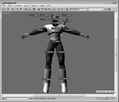
- Before moving any of the nodes, enable the Lock Zoom/Pan option in the Schematic View Preferences dialog box so the image resizes with the nodes. Then select each of the nodes, and drag them so they are roughly positioned on top of the part they represent. Start by moving the parent objects first, and then work to their children.
Figure 25.21 shows all the nodes aligned over their respective parts. From this arrangement, you can clearly see how the links are organized.
FIGURE 25.21 Using a background image, you can see how the links relate to the model.
Using List Views
One of the last uses of the Schematic View is to list all nodes that have things in common. Using the List Views menu, you can select to see All Relationships, Selected Relationships, All Instances, Selected Instances, Show Occurrences, and All Animated Controllers.
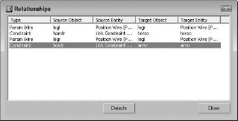
The List Views ![]() All Relationships menu command displays a separate dialog box, shown in Figure 25.22, containing a list of nodes and their relationships. The Selected Relationships menu command limits the list to only selected objects with relationships. The List Views dialog box also includes a Detach button to remove the relationships if desired. Double-clicking a relationship in the list opens its dialog box, where you can edit the relationship.
All Relationships menu command displays a separate dialog box, shown in Figure 25.22, containing a list of nodes and their relationships. The Selected Relationships menu command limits the list to only selected objects with relationships. The List Views dialog box also includes a Detach button to remove the relationships if desired. Double-clicking a relationship in the list opens its dialog box, where you can edit the relationship.
Tip
You can click each column head to sort the entries.
The List Views ![]() All Instances menu command displays all the instances found in the scene. This includes all types of instances, including geometry, modifiers, controllers, and so on. For the Instances list view, the Detach button is replaced with a Make Unique button.
All Instances menu command displays all the instances found in the scene. This includes all types of instances, including geometry, modifiers, controllers, and so on. For the Instances list view, the Detach button is replaced with a Make Unique button.
FIGURE 25.22 The List Views dialog box includes a list of nodes with relationships.
Note
Another way to identify instances is to look for bold text in the node. All label text for all instanced nodes is displayed in bold.
If a node is selected and you want to see all other nodes that share the same type of relationship or share a property, the List Views ![]() Show Occurrences menu command displays them. The final list view shows All Animated Controllers.
Show Occurrences menu command displays them. The final list view shows All Animated Controllers.
Summary
Working with containers and XRefs lets you combine the work of several users and creatively collaborate across teams. Some tasks in the viewport, such as linking objects into a hierarchy, can be difficult. The Schematic View represents all data as simple rectangular nodes. These nodes make easy work of accomplishing a variety of tasks.
This chapter covered the following topics:
- Using containers and externally referenced scenes and objects to work on the same project at the same time as your fellow team members without interfering with their work (or they with yours)
- Configuring XRef paths to help Max track your XRef Scenes and Objects
- Viewing all objects as nodes using the Schematic View window
- Learning the Schematic View interface
- Using the Schematic View window to select, delete, and copy objects, materials, and modifiers
- Using the Schematic View to assign controllers and wire parameters
- Setting preferences for the Schematic View window
- Listing views of nodes with common properties
In the next chapter, you learn more about features that enable deforming meshes, including the Paint Deformation tool and various modifiers that may be applied to mesh objects.