11
Active Blade Twist in Rotary UAVs using Smart Actuation
Pascual Marqués
Marques Aviation Ltd, Southport, UK
11.1 Introduction

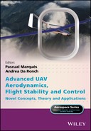
Figure 11.1 MA THOR Heli VTOL‐UAS.
Image: Marques Aviation Ltd.
Helicopter rotors operate in a complex unsteady aerodynamic environment characterised by cyclic variation of centrifugal and aerodynamic loads on the rotating blades (Figure 11.1). Various aerodynamic phenomena occurring on the helicopter rotor generate vibration and noise, and these are most pronounced in forward flight and during descent. In forward flight, the advancing blade can undergo airflow velocities close to the speed of sound; in this transonic regime shock waves can be generated. The retreating blade can experience dynamic stall and stall flutter (Feszty and Nitzsche 2011; Figure 11.2).
Both shock waves and dynamic stall cause vibration on the rotor, which is transferred through the shaft to the fuselage. Moreover, the helical tip vortex developed by each blade interacts with the other blades in a phenomenon known as BVI, which is an additional source of vibratory loads and noise. The amplitude of vibration recorded inside the fuselage of a helicopter is typically about 0.4 g and the frequency of peak vibration is between 1/rev and N/rev; where, N signifies the number of blades (Konstanzer et al. 2008). Therefore, typical frequencies are in the range of 2–8 Hz depending on the size of the helicopter.
Helicopter noise caused by the rotor aerodynamics typically reaches 80–120 dB in the far‐field, and represents the addition of BVI noise, swishing noise and rotational noise. BVI is the main source of the characteristic ‘slapping’ noise of helicopters. Swishing noise is a broadband noise associated with the random fluctuation of blade lift caused by vortex shedding from the blade ahead, fluctuations in the airflow velocity or flow separation. Rotational noise is produced by the periodic forces applied to the air around the azimuth of the rotor disk. Rotational noise has been associated with vibration of the fuselage (Feszty and Nitzsche 2011; Pagano et al. 2011).

Figure 11.2 Spanwise distribution of relative airflow velocities.
Source: Paternoster et al. 2012.
The sources of noise and vibration are strongly coupled, because they are often caused by the same aerodynamic phenomena (such as BVI). Suppression of rotor vibration on helicopters has several advantages, including enhanced forward flight performance, use of lighter aircraft components because parts are exposed to less fatigue loading, extended component life, and reduced helicopter operational costs (Feszty and Nitzsche 2011). In particular, excessive vibration in the control system limits the maximum forward flight speed before the maximum power of the propulsion unit is reached. Active blade twist attenuates noise and vibration and also improves hover performance because of the better spanwise distribution of aerodynamic loads. There is more uniform downwash in the far wake, leading to lower induced power. However, very low and even negative angles on the tips of rotor blades have the potential to adversely affect forward flight performance and increase vibratory loads, hence the importance of blade twist optimisation (Johnson et al. 2012). Passive devices suppress vibration over a narrow frequency range, but active blade control systems attain vibration suppression across a broad band of frequencies. In particular, rotor‐based active control systems that attenuate vibrations and noise at their source – the rotor blade – are considered superior (Baier and Datashvili 2011; Feszty and Nitzsche 2011; see also Figure 11.3).

Figure 11.3 Concept of embedding the Maxon A‐22 motor and gearbox unit at the root of the SHARCS (smart hybrid active rotor control system) blade.
Source: Feszty and Nitzsche 2011.
There have been considerable efforts in the helicopter community to control the sources of fuselage vibration and rotor noise. Advances in active materials allow the embedding or surface‐mounting of multiple lightweight sensors and actuators at selected locations in the rotor blades (Shin et al. 2007). Active materials provide advantages, in terms of weight and power consumption, over the hydraulic systems that have been used previously. Various implementations of embedded actuators have been suggested. The integral twist actuation concept, which uses active materials technology, has shown promising benefits in hover testing with small‐scale models (Shin et al. 2007). Advanced active rotor blade technology requires a sensing/actuation system. This can be achieved using piezoelectric transducers integrated within a flexible host structure (Shevtsov et al. 2009). Distributed power actuators capable of modifying the local blade twist enhance a helicopter’s flight performance and effectively reduce the noise and vibration levels. Performance benefits include reduction in cruise lift‐dependent drag, less rotor power consumption, increased aeromechanical stability, and delay of the onset of stall flutter; thus significantly expanding the flight envelope. Engineering advancements in active rotor blade design include the introduction of high‐stroke on‐blade piezostack actuators in rotors with trailing‐edge flaps. Examples of piezostack actuators are macro‐fibre composites (MFCs) and active fibre composites (AFCs), which include a layer of extruded piezoceramic fibres encased in a protective polymer matrix material and interdigitated electrodes that generate electrical fields in the plane of the actuator. However, piezoceramic fibres present technological difficulties in their manufacture, so piezoelectric actuators formed as plate‐like patches or layers bonded to the surface of the host structure are used more frequently (Shevtsov et al. 2009). For efficient control of structural vibration, it is important to select the correct type, number and location of piezoelectric patch actuators. This requires a process of optimization. However, the optimization problem in helicopters has a notable constraint in that the actuators must be controlled by a high voltage transmitted from power amplifiers (in other words, piezodrivers), which complicates the design of the hub and rotor.
Design and optimization of adaptive helicopter rotor blades requires an interdisciplinary approach, incorporating structural mechanics, aerodynamics, rotor dynamics, actuator technology, power‐electronics and control. The same aerodynamic principles that apply to manned helicopters must also be considered in the design of rotor unmanned aerial vehicles (RUAVs). Often, RUAVs provide an ideal ‘low‐risk’ platform in which to test novel rotor technologies. This chapter presents an evaluation of actuation concepts that underlie active blade twist technology and aspects of integral twist actuation and rotor optimisation. It thus provides a reference in the design of advanced RUAVs. The chapter explores the following themes:
- Actuation concepts: the source of vibrations and noise in helicopters, higher harmonic control, individual blade control, the smart spring concept, SMART active flap control, actuation concepts, and applications of active‐twist rotor control in RUAVs.
- Integral twist actuation: embedded active fibre composite actuators, single crystal piezoelectric fibre composites, the SHARCS project, smart spring systems, active and passive piezoelectric patches, swashplateless helicopter rotors and active servopaddles, progress in rotor‐based active control technologies, optimization frameworks for active twist rotor blades, and rotor blade optimization using CFD.
11.2 Actuation Concepts
11.2.1 The Source of Vibration and Noise in Helicopters
Modern helicopters suffer from noise, vibrations, and limited flight envelopes. Improvements in recent years have been due to better rotor aerodynamics, novel planforms and airfoils, advanced tail rotor designs, composite materials, hingeless and bearingless rotors, and passive and active vibration damping (Maucher et al. 2007). Rotor vibrations are more prominent in forward flight. Variations in the spanwise distribution of lift and drag excite the blade’s bending modes. This generates alternating rotor hub loads consisting of vertical forces, and lateral and longitudinal mast moments. The vibration frequencies are a multiple of the number of blades and the revolution frequency. Using more rotor blades and a smaller flapping hinge offset reduces vibrations. Deficient blade tracking is also a source of vibrations (Maucher et al. 2007).
The acoustic signal of the helicopter rotor consists of broadband and impulsive noise. The broadband noise originates from boundary‐layer effects on the rotor blades (known as self‐noise) at high frequencies, and blade–wake interaction (BWI) and BVI at medium frequencies. BWI persists over a large range of flight conditions. The low‐frequency impulsive sources are dominant in high‐speed forward flight and in descent. In descent flight and low‐speed manoeuvres, the rotor blades encounter tip vortices emanating from preceding blades. BVI causes loud slapping noises. In high‐speed forward flight, the airflow at the blade tip becomes transonic, producing shock waves and loud noise directed in the flight direction; this is known as high‐speed impulsive noise (HSI). Harmonic and higher harmonic loading noise are additional low‐frequency sources of noise originating at the main rotor (Maucher et al. 2007).
11.2.2 Higher Harmonic Control
The majority of the research into active control of rotorcraft has attempted to eliminate rotor vibrations and noise problems by addressing the source – the aerodynamic loads – by modifying the periodic aerodynamic loads, such that they no longer produce the detrimental effects (Wilbur and Wilkie 2005). The simplest method is to modify the rotor blade pitch at harmonic frequencies above the rotor rotational frequency. The concept of HHC was introduced in the 1970s and ultimately flight‐tested at full scale. Flight tests showed that HHC reduces vibration and noise by changing the pitch at the root of the blades via the swashplate. HHC superimposes the standard blade‐pitch variation with a low‐amplitude blade pitch at multiples of the rotational frequency (Maucher et al. 2007). In the 1980s, HHC was used in helicopters such as the OH‐6A, S‐76 and SA 349 Gazelle; the technology was also tested in a wind tunnel (Yu et al. 2002).
11.2.3 Individual Blade Control
Individual blade control (IBC) typically uses hydraulically actuated pitch links to control each rotor blade independently. The advantages of IBC systems over HHC systems include better simultaneous attenuation of vibration and noise, shaft power reduction, and extension of the flight envelope (Maucher et al. 2007). However, the difficulty with IBC arises in providing the necessary hydraulic power in the rotating system (Wilbur and Wilkie 2005). As a result, many active rotor control concepts incorporate on‐blade controls, typically trailing‐edge flaps or strain‐induced blade twist, actuated by piezoelectric systems (Figure 11.4). In the IBC system, actuators are placed on the blade to suppress vibration at the source (Nitzsche et al. 2004). In the past, active IBC has been implemented using discrete and integral actuation. Discrete actuation uses an active actuator embedded in the blade and this activates a trailing‐edge servo‐flap. However, discrete actuation requires complex displacement amplification devices that must also be robust so that they can operate under the extreme dynamic environment that is characteristic of the helicopter rotor (Nitzsche et al. 2004). Integral actuators are either embedded or bonded to the skin along the blade span, and therefore produce a smooth continuous structural deformation (Nitzsche et al. 2004). Integral actuators require very high voltages to induce sufficient actuation of the AFC elements. Peak‐to‐peak driving voltages of 3000 V have been employed to generate the required blade twist and suppress rotor vibrations (Kessler et al. 2003).
Successful implementation of IBC systems has been hindered in the past by electromechanical limitations of smart material actuators, in particular piezoceramic actuators. The limited deformation capabilities of piezoceramic actuators necessitates the use of complex displacement amplification mechanisms or the application of very high voltages to control rotor vibration. The smart spring concept provides IBC and overcomes the limitations of piezoceramic actuators (Nitzsche et al. 2004).

Figure 11.4 Trailing‐edge flap and actuation system.
Source: Paternoster et al. 2012.
11.2.4 Smart Spring Concept
Suppression of rotor vibrations in helicopters using IBC can be achieved by altering either the time‐varying loads on each blade or the stiffness of the blades according to the variable aerodynamic loads (Nitzsche et al. 2004). The smart spring concept actively alters the blade dynamic stiffness to suppress rotor vibration. The system is particularly effective when positioned near the blade root to alter its boundary conditions. The smart spring concept does not require the transmission of high voltages along the blade span and reduces the likelihood of the electromagnetic interference that was present in previous IBC systems (Nitzsche et al. 2004). Thus, by altering the structural response of the blade, rather than the aerodynamic characteristics, the smart spring embodies a unique approach to helicopter IBC.
11.2.5 SMART Active Flap Control
Straub et al. (2004) developed a full scale SMART system that uses piezoelectric actuated blade flaps. Previous simulations and model‐scale wind tunnel tests showed that the SMART system achieves an 80% reduction in vibration, 10‐dB noise attenuation for a helicopter passing overhead, and higher aerodynamic performance. Tests in a whirl tower demonstrated the functionality, robustness, and control authority of the active flap system. The effectiveness of the SMART system is due to the success in adapting piezoelectric materials and actuators to rotor blades, and meeting actuator–blade integration requirements. The application of the SMART technology was perceived as a precursor for the elimination of the swashplate (Straub et al. 2004).
11.2.6 Actuation Concepts
The main advantages of active twist are that the aerodynamic profile does not change and there are no moving parts. Grohmann et al. (2006) described different actuation concepts that deform the helicopter rotor blades and control rotor aerodynamics. Their analysis focuses on blade twist and airfoil camber variation that can be implemented using piezoceramic actuation. The direct‐twist concept and trailing‐edge flaps have also been the focus of attention of previous research (Maucher et al. 2005). Discrete flaps are the most straightforward means to obtain camber variation. Leading‐edge flaps increase maximum airfoil lift incurring separation and fluctuations of the pitching moment and are used for dynamic stall alleviation. A method of achieving blade twist involves the so‐called servo effect of a trailing edge flap, whereby deflection of a servo flap generates aerodynamic pitching moments that twist the blade. The change in aerodynamic pitching moment twists the rotor blade aeroelastically. The actuation system uses piezoceramic stack actuators. A mechanical amplification of the active stroke is necessary. The servo effect was demonstrated on a BK117 helicopter which was flight tested by Eurocopter in 2005 (Jänker et al. 2006; Roth et al. 2006; see also Figure 11.5). An electronic system comprising a controller unit, power electronics, data acquisition and data and power transmission is required to operate piezoelectrical driven actuators (Maucher et al. 2007).

Figure 11.5 BK117 fitted with servo flaps.
Source: Maucher et al. 2007.
Blade twist is also achieved by structure‐borne twist actuation. This causes a spanwise variation of lift distribution without affecting the aerodynamic pitching moment. Blade twist concepts embed plies of piezoelectric fibres in the rotor blade’s skin. The active fibres are arranged in a way that induces strain at ±45° from the blade spanwise axis to generate maximum twisting moment. Control of each individual rotor blade using on‐blade actuation by active materials offers advantages in terms of weight, power consumption and bandwidth compared to systems actuating the rotor blade root (Maucher et al. 2007). The active trailing‐edge (ATE) concept provides continuous blade deformation by displacing the trailing edge upwards and downwards (Figure 11.6). Similar to trailing‐edge flaps, ATE aims to twist the blade aeroelastically using the servo effect; that is, the change in aerodynamic pitching moment twists the rotor blade (Maucher et al. 2007). In an ATE system, an active tab may be fitted to the trailing edge of the helicopter blade. Alternatively, the ATE actuator may be integrated into the airfoil (Grohmann et al. 2006). The actuator consists of a multi‐morph bender that includes piezoelectric ceramics and glass‐fibre reinforced plastics. The ATE concept allows smooth deflection of the airfoil contour in the chordwise direction. An ATE leaves no gaps at the ends of the deflected active surfaces in the spanwise direction, thus preventing parasitic drag and discrete wake vortices.
Figure 11.6 ATE technology provides smooth deformation of the helicopter blade
(Grohmann et al. 2006)
Optimization of the ATE actuator requires a multidisciplinary approach. Aero‐servo‐elastic optimization demands the smart aerostructure be flexible for large active deflections, as well as having the minimum mass, low electric power consumption, and substantial aerodynamic effectiveness. The minimum mass of the piezoelectric actuator is important, but there may be a need for an additional balancing weight to keep the centre of mass at 25% of the chord length. Structural interfaces and power amplifiers also add weight to the actuation system. Blade twist is also achieved using an active reflexed skeleton line, which removes variations in pitching moment. The active reflexed skeleton line is realised by deflecting the ATE in one direction at its upstream root while the downstream chord portion is deflected inversely. An active blade tip controls tip vortices, and therefore BVI and transonic effects such as HSI. The ATE actuator is easily integrated into an active blade tip. An ATE does not contain components close to the leading edge and can be fitted to the varying blade chord and small airfoil thickness of parabolic blade tips (Figure 11.7).

Figure 11.7 Geometry of the Advanced Technology Rotor.
Photo: Marques Aviation Ltd.
Adaptive helicopter rotor concepts such as active blade twist use large assemblies of piezoelectric actuators integrated in composite structures, such as glassfibre‐reinforced plastics. Different sets of piezoelectric actuators, such as MFC actuators, are employed to simplify the manufacturing process. MFCs are piezoelectric devices that have structural flexibility and high actuation authority. However, a limitation of piezoelectric actuators is that they require a high voltage input (Bilgen et al. 2011). The modular design of the ATE actuator simplifies maintenance because the actuator is easily detached from the host blade structure for replacement.
Piezoceramics are a suitable actuation technology for morphing helicopter rotor blades, because of their efficient electrical power supply, robustness in hostile environmental conditions, such as when there are high levels of vibration, and high bandwidth. In particular, d33‐mode actuation is suitable for rotor blades. Piezoceramics offer potential for applications in the commercial helicopter market because of their low manufacturing cost and easy integration, reliability and maintenance (Grohmann et al. 2006).
For an active rotor blade, the actuation must be integrated into the aerodynamic shape without incurring substantial additional weight. Flap and bending stiffness of an active design should be equivalent to those in a passive rotor blade. Also, the centre of gravity must remain at the 25% chord line. The actuation mechanism of an active blade must withstand the large loads and the strains of the blade structure caused by high centrifugal forces, flapping accelerations, lead‐lag bending, flapping, and blade torsions. In addition, modularity of the active devices is desirable, so as to facilitate maintenance and repair in active rotors (Maucher et al. 2007). In their project, Maucher et al. (2007) employed a three‐layer (tri‐morph) bender made up of piezoceramic actuators and a glassfibre‐reinforced plastic core. The ATE had no discrete hinges and the authors presented three ATE options:
- Smart tab: The bending actuator is attached to the airfoil’s trailing edge. The tab presents a long lever from the blade’s neutral axis at 25% chord. Thus, the smart tab achieves a higher aerodynamic moment for a given deflection of the actuator. However, additional mass is necessary to balance the centre of gravity. The smart tab brings a degradation in aerodynamic performance, as the centre of pressure of the profile is no longer at 25% chord. Hence, only small smart tabs may be used (Maucher et al. 2007; see also Figure 11.8).
- ATE: The bending actuator is integrated within the airfoil’s trailing edge and does not change its aerodynamic shape. A flexible filler material maintains the shape of the airfoil and ensures the continuous transition between the deflected and the passive trailing edge in the spanwise direction. This continuity reduces parasitic drag and discrete wake vortices of the deflected ATE (Maucher et al. 2007). The ATE achieves high authority. Its smaller leverage to the neutral axis of the blade requires less additional mass to equilibrate the centre of mass. Its stiffer design results in higher resonance frequencies than the smart tab. Furthermore, the ATE does not contain components close to the leading edge and permits the design of an active blade tip. In fact, the ATE can be combined with varying blade chord and small airfoil thickness at the blade tip.
- Blend: A blend of the two concepts.

Figure 11.8 Smart tab and ATE technology for smooth deformation of the helicopter blade.
Source: Maucher et al. 2007.
11.2.7 Applications of Active‐twist Rotor Control in RUAVs
RUAVs require the application of active‐twist rotor control technology (Wilbur and Wilkie 2005). Active‐twist rotor control systems use piezoelectric fibre composite actuators and achieve vibration and noise reduction, enhancements in rotor performance, active blade tracking, and stability augmentation. As in piloted helicopters, the rotor system of unmanned helicopters encounters a highly variable aerodynamic environment (Figure 11.9), which induces high vibratory loads, noise, poor performance, instabilities, difficulty in maintaining rotor blade track, and limitations on load capacity and forward flight speed. Therefore, active twist may be applied to RUAVs that incorporate a conventional helicopter main‐rotor/tail‐rotor configuration. Examples of these vehicles include the A‐160 Hummingbird, RQ‐8A Fire Scout, Vigilante, Bell HV‐911 Eagle Eye, and MA THOR Heli.
Figure 11.9 The complex aerodynamic environment in forward flight in which the RUAV’s rotor operates.
Source: Wilbur and Wilkie 2005.
11.3 Integral Twist Actuation
11.3.1 Embedded Active Fibre Composite Actuators
The integral twist actuation concept offers several potential benefits: there is redundancy in operation, it does not increase the profile drag of the blade (something which is characteristic of discrete flap concepts), and the actuators are embedded in the composite construction, therefore becoming part of the load‐bearing structure. Therefore, the active blade becomes a truly integrated multifunctional structure, and this facilitates their construction and assembly.
Shin et al. (2007) examined the integral twist deformation of blades and the aeroelastic behaviour of blades equipped with active fibre composite actuators embedded in them. Rotor performance was evaluated in different flight conditions. The aeroelastic model utilised in the analysis consists of a three‐dimensional electroelastic beam with geometrical‐exactness, coupled with finite‐state dynamic inflow aerodynamics (Shin et al. 2007). A system identification method estimates the harmonic transfer function of the rotor. The linear time‐periodic (LTP) and linear time‐invariant (LTI) components of the transfer functions are extracted. The helicopter rotor becomes an LTP system during forward flight due to a periodicity in aerodynamics, so the LTP components exist and may impact the closed‐loop response. Shin et al. (2007) designed a vibration‐minimizing controller that implements a classical disturbance rejection algorithm with some modifications. The closed‐loop controller was numerically simulated and the capability for hub‐vibratory load reduction was demonstrated.
11.3.2 Single Crystal Piezoelectric Fiber Composites
Park and Shin (2007) presented the design of a novel integral twist‐actuated blade that uses single‐crystal piezoelectric fibre composites. These composites efficiently reduce the vibration and acoustic signal of helicopters. Previously, the active twist rotor (ATR) blade had been investigated by Park and Shin (2007). The ATR blade utilizes piezoelectric fibre composite actuators, such as AFC or MFC, that are embedded within the composite blade structure and cause direct twisting deformation of the blade. The ATR blade could effectively reduce vibration and noise in rotorcraft, but a high input voltage of about 4000 Vpp was required. Nonetheless, single‐crystal piezoelectric materials can produce strain levels five times larger than those of conventional piezoceramics. Park and Shin (2007) suggested the development of a new ATR blade that incorporates single crystal MFCs. The new ATR concept is known as the Advanced Active Twist Rotor (AATR) blade. The AATR blade can reduce the vibration and acoustic signals of the helicopter more efficiently. However, much lower input voltages and active region lengths are used than in previous ATR blade concepts. Design and analysis of the blade structure consisted of a two‐dimensional cross‐section analysis and a one‐dimensional beam analysis. The cross‐section modelled as a two‐cell composite beam is shown in Figure 11.10.

Figure 11.10 Two‐cell, thin‐walled beam used for the two‐dimensional cross‐section analysis.
Source: Park and Shin 2007.
The sectional properties obtained in terms of the length of the active region are shown in Figure 11.11. As the active region length is increased, the flapwise‐bending stiffness decreases considerably, but the torsional and chordwise‐bending stiffness remain unaltered (Park and Shin 2007).
Figure 11.11 Cross‐section of the AATR blade (NACA0012 airfoil).
Source: Park and Shin 2007.
Figure 11.12 shows the dynamic frequency response of the AATR blade under the aerodynamic load in hover. At 5/rev excitation frequency, the AATR blade achieves a tip twist actuation amplitude of 4° with 75% lower input voltage and 20% smaller active region than an ATR blade. The AATR blade more effectively attenuates helicopter vibration (Park and Shin 2007).

Figure 11.12 Frequency responses in hover.
Source: Park and Shin 2007.
Park et al. (2008) later identified various issues regarding the application of AATR technology in full‐scale rotors. Single‐crystal piezoelectric actuators are difficult to manufacture in large sizes. Also, severe brittleness in the material needs examining. Park et al. (2008) proposed a new AATR, the AATR‐II blade, which has an improved twist actuation performance that reduces vibratory loads in forward flight using much lower input voltages. The AATR‐II blade requires only 10% the input voltage of the ATR design.
11.3.3 The SHARCS Project
The appearance of vibration and noise is strongly coupled in helicopter; when one is reduced, the other one is amplified. It is therefore desirable to introduce simultaneous reductions of vibration and noise using multiple or hybrid active control devices in each blade. Mander et al. (2008) described the design of the Active Pitch Link (APL) device developed for the SHARCS project. This project demonstrates simultaneous reduction of vibration and noise in helicopters using a hybrid system that integrates three independent active control systems on the helicopter blade: APL, ACF and ACT. The APL and ACF systems primarily reduce vibration, whereas ACT reduces noise.
The project involved the design and construction of a four‐bladed scaled rotor of 1.096 m radius, and the testing of the system in a wind tunnel. Static tests showed that the system stiffness could be varied continuously between two extremes to attain vibration and noise suppression. The final design fulfilled the three main design criteria: observability, controllability and failsafe design. The last of these is important because it ensures that when the actuator fails, the APL retains the function of a conventional pitch link. The design is easily scalable to larger sizes, thus providing opportunities for flight testing in full‐scale helicopters. Feszty et al. (2009) and Feszty and Nitzsche (2011) have demonstrated the capabilities of the SHARCS hybrid control concept using whirl tower testing (Figure 11.13). The hybrid control combines a flow control device (such as ACF or ATR), and a structural or stiffness system on the helicopter blade. The structural control system uses an APL that dynamically controls the torsional stiffness of the blade.

Figure 11.13 Active pitch link installed in the Carleton whirl tower facility.
Source: Feszty and Nitzsche 2011.
11.3.4 Smart Spring System
In helicopter rotors composed of identical blades, the rotor hub cancels the majority of the vibratory loads except for the harmonic multiples of the number of blades. Control of the blade aeroelastic response has been a matter of research interest in the helicopter industry. Smart materials have been studied extensively. Smart materials have a limited stroke, but they are able to generate large forces. The limitations of smart materials are overcome with the use of smart springs, which indirectly control vibration of the rotor (Oxley et al. 2009). The smart spring system is particularly effective in altering the boundary conditions of a structure and it is incorporated at the root of the blade. The smart spring functions as a mechanical filter that attenuates the higher harmonic vibratory loads caused by the unsteady aerodynamic loads on the blade. The technology is best suited for integration with an IBC system and another flow‐control device, such as a servo flap or an ACF‐embedded blade (Nitzsche et al. 2005). It has been shown that small changes in the nominal stiffness of the blade root can attenuate vibratory loads with up to 90% efficiency. This is because modifying the boundary conditions usually significantly influences the vibration characteristics of a mechanical system. The forces transmitted through the pitch link with the smart spring were 44% of the original value at 4/rev and 62% of the original value at 8/rev. These are modest gains compared with other active vibration reduction mechanisms used in helicopters (Oxley et al. 2009).
11.3.5 Active and Passive Piezoelectric Patches
Shevtsov et al. (2009) compared the efficiency of rotor‐blade vibration suppression by active (controlled) and passive (shunted by electrical circuit) piezoelectric patches. For reasonable load capacitance, inductance and resistance, effective suppression of oscillations was achieved at frequencies above 1 kHz only. Active rotor‐blade technology requires a sensing–actuation system. Piezoelectric transducers disposed on a controlled flexible host structure can reduce noise and vibration levels, reduce lift‐dependent drag, minimize rotor power consumption, improve aeromechanical stability, and delay the onset of stall flutter. MFCs or AFCs consist of a layer of extruded piezoceramic fibres encased in a protective polymer matrix (Figure 11.14). Interdigitated electrodes generate electrical fields in the plane of the actuator. Optimal placement of an optimal number of piezoelectric actuators is essential for the successful structural control of the blade.
Passive piezodamping concepts offer a low‐cost solution and do not require complicated electronics. The shunt circuit does not require an external power source, is small, and maintains its integrity under centrifugal loading. Passive shunt damping consists of connecting a passive electrical circuit to the electrode terminals of a piezoceramic patch attached to the host structure. Considering a shunted harmonically excited piezoelectric plate, the passive mode can be effective for vibration suppression in high natural modes only. Shevtsov et al. (2009) concluded that active vibration damping is more efficient for harmonic excitation. In contrast, the passive mode is suitable for the suppression of large‐spectrum oscillations caused by impulse loads.

Figure 11.14 Components of an AFC actuator.
Source: Paternoster et al. 2012.
11.3.6 Swashplateless Helicopter Rotors and Active Servopaddles
Leishman (2006) estimated that the swashplate, hub and shaft account for 35% of the entire helicopter parasitic drag. Therefore, eliminating the swashplate and related hydraulic actuation and replacing them with control inputs directly on the blade should yield significant performance improvements. Other advantages of the swashplateless rotor include decreased empty weight of the helicopter, parasitic drag, number of mechanical parts, maintenance requirements, fuel consumption, and acquisition and operating costs (Brindejonc 2009). Stringent volumetric constraints in the rotor blade, and the high centrifugal and vibration loads experienced near the tip of the blade make elusive the practical implementation of on‐blade aerodynamic controls. Brindejonc (2009) reported the design and testing of a new actively controlled Hiller‐type servopaddle to achieve helicopter rotor control. The rotor is swashplateless and the blades are coupled to a servopaddle fitted with a piezo‐electrically actuated aileron positioned behind the trailing edge of the paddle. The aileron is deflected by the actuator, generating lift and a variation of the paddle pitch moment and lift. The system consists of a blade, paddle and aileron assembly. The active servopaddle is capable of generating both cyclic and collective inputs. A system of this type reduces mechanical complexity, parasitic drag and weight. This, in turn, reduces the fuel consumption of the aircraft. The evaluation of this novel concept for a full‐scale production helicopter requires substantial analytical development and systematic testing at different scales. An appropriate controller incorporated into the flight control system must be used for actuating the paddles.
11.3.7 Progress in Rotor‐based Active Control Technologies
There are four types of rotor‐based active control technologies: ACF, ATR, ACT and APL. The ACF, ATR and ACT technologies are classified as blade‐based mechanisms and APL is a hub‐based device (Feszty and Nitzsche 2011; see also Figure 11.15).
ACF represents advanced technology. It is a blade‐based active control technology that has been flight tested in several research programs, such as the Eurocopter in 2005 (Roth et al. 2006). The ACF can usually be optimized to reduce either vibration or noise, at the expense of the other (Straub et al. 2004). ATR also attenuates noise and vibratory loads, but it requires much higher voltages and consumes more power. The absence of moving components in ATR makes it more reliable and suitable for harsh environments, such as those with dust or snow. The ACT system modifies the anhedral of the blade tip and it is activated by the pilot some 30 s before entering a particular flight regime. The principle of operation of ACT consists of reduction of BVI noise and vibration, which is achieved by displacing the helical tip vortex and thus controlling the BVI miss‐distance, or the blade‐to‐tip‐vortex distance. The APL system changes the blade pitch angle and hence the aerodynamic loads (Feszty and Nitzsche 2011).

Figure 11.15 SHARCS hybrid concept with four active blade control systems.
Image: Feszty and Nitzsche 2011.
11.3.8 Optimization Framework for Active Twist Rotor Blades
Optimization of ATR blades that use embedded anisotropic piezocomposite actuators was conducted by Mok (2010). Optimization of active twist blades is a complex task that involves a highly nonlinear design space with tightly coupled design variables. The optimization framework for blade cross‐sectional design combines different analytical components including cross‐sectional analysis (UM/VABS), an automated mesh generator, a beam solver (DYMORE), a three‐dimensional local strain recovery module, and a gradient based optimizer within MATLAB. In the mathematical optimization problem, the static twist actuation performance of a blade is maximized within a series of blade constraints: locations of the centre of gravity and elastic axis, blade mass per unit span, fundamental rotating blade frequencies, and the blade strength and strain fields. Resolutions to the limitations of the optimisation process include mesh overlapping, element distortion, trailing‐edge tab modelling, electrode modelling, foam implementation of the mesh generator, and sensitivity of the optimization scheme. An example of the effectiveness of this process is its application to a scale model of the AH‐64D Apache blade, which demonstrated the capability of this framework to explore the nonlinear design space of complex planforms. The optimization framework is an effective tool to design high‐authority active twist blades that reduce helicopter vibrations (Mok 2010).
Active materials, commonly called smart materials, have properties that change by an external input, including stress, temperature, pH (acidity), electric or magnetic fields, and moisture. The deformation of shape‐memory alloys is induced and recovered by means of temperature changes. Electrorheological and magnetorheological materials are fluids that undergo a dramatic change in their viscosity in the presence of an electric or magnetic field, respectively. Piezoelectric materials produce a voltage upon application of a mechanical stress, and vice versa. Therefore, a structural property, such as stress, is easily controllable using an electric field. There are two types of piezoelectric materials: piezoceramic (PZT) and piezofilm (PVDF). PZT is used as an actuator due to its high strength. MFCs were developed at NASA Langley. They follow the same principles as AFCs and use piezoelectric fibres and inter‐digitated electrodes. Unidirectional piezoceramic fibres are embedded into a thermosetting polymer matrix and sandwiched between Kapton sheets layered with copper inter‐digitated electrodes. MFCs have lower fabrication costs than AFCs. Mok (2010) designed an advanced ATR blade based on the AH 64D Apache blade but at 1/6 scale. This had 2.5 times more authority than its predecessor (Figure 11.16). Advanced airfoils, enhanced blade planform and MFC integrated actuator design were introduced to the nonlinear design space using a nested‐loop optimization approach.
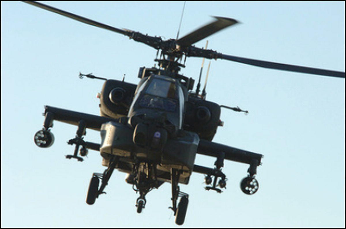
Figure 11.16 AH‐64 Apache helicopter.
Image: Petty Officer 3rd Class Shawn Hussong, US Navy.
11.3.9 Rotor Blade Optimization Using CFD
The work of Johnson and Barakos (2011) and Johnson et al. (2012) emphasises the fact that the design of rotor blades is complex and involves several disciplines of engineering, including aerodynamics, structural analysis, dynamics, aeroelasticity and control systems, thus requiring a multidisciplinary approach. Johnson et al. (2012) presented a framework for the optimisation of various design parameters of rotor blades in the forward‐flight dynamic condition (unsteady conditions). Optimization methods consisted of CFD combined with meta‐models, including artificial neural networks, kriging interpolation, and a non‐gradient‐based optimiser using genetic algorithms. The optimization approach was also demonstrated in the application of linear twist of rotors in hover (steady case). Rotor blade tip optimisation included the anhedral and sweep of the UH60‐A rotor blade in forward flight and a BERP‐like rotor in forward flight; constraining hover performance in both cases. The findings of Johnson et al. (2012) suggest optima in agreement with engineering intuition and the metamodels were also validated with high‐fidelity CFD data. The CFD database required for the metamodel was extensive. Therefore, the harmonic balance alternative for obtaining the CFD data was used, rather than time‐marching, to increase computation efficiency during the optimisation of the BERP‐like blade tip. Johnson et al. (2012) successfully combined a metamodel with high‐fidelity CFD data to efficiently obtain high‐resolution performance using a non‐gradient‐based method.
11.4 Summary
As in piloted helicopters, the rotor system of RUAVs encounters a highly variable aerodynamic environment. The simplest method of modifying the periodic aerodynamic loads that cause helicopter noise and vibration is to implement HHC, which changes the pitch at the root of the blades via the swashplate. HHC superimposes the standard blade pitch variation with a low amplitude blade pitch at multiples of the rotational frequency. IBC controls each blade independently using hydraulically‐actuated pitch links. IBC systems are superior to HHC, however the challenge with IBC arises in providing the necessary hydraulic power. Unlike IBC, the smart spring concept does not require the transmission of high voltage along the blade span. The smart spring alters the structural response of the blade, rather than the aerodynamic characteristics. In the servo effect method, deflection of a servo flap using piezoceramic stack actuators generates aerodynamic pitching moments that twist the blade aeroelastically. The ATE concept provides continuous deformation of the blade trailing edge upwards and downwards, and twists the blade aeroelastically using the servo effect; that is, by exploiting the change in aerodynamic pitching moment of the blade. The ATE actuator incorporates piezoelectric ceramics and glass fibre reinforced plastics and may be integrated into the airfoil. Different sets of piezoelectric actuators are employed to simplify the manufacturing process; such as MFC actuators that offer structural flexibility and high actuation authority. Three methods have been proposed for the integration of actuation into the aerodynamic shape: Smart tab, ATE, and a blend of these two. The helicopter industry has been reluctant to pursue active rotor control systems aggressively due to the complexity, development costs, and inherent risks. However, the risk is reduced by implementing and testing active rotor control technology on RUAVs first. This also allows advanced RUAV concepts to acquire the active blade twist technology.
Advances in active materials allow embedding or surface‐mounting multiple lightweight sensors and actuators at selected locations in the rotor blades. Integral twist deformation of blades using active fibre composite actuators embedded in the composite blade offers several benefits, including redundancy in operation, low profile drag, and the actuators becoming part of the load bearing structure. Novel integral twist actuated blades use single crystal piezoelectric fibre composites that efficiently reduce the vibration and acoustic signal of the helicopter. Single crystal piezoelectric materials can produce strain levels five times larger than those of conventional piezoceramics. The AATR blade incorporates single crystal MFC and requires much lower input‐voltage and active region length than ATR blade concepts. The SHARCS project demonstrated simultaneous reduction of vibration and noise in helicopters using a hybrid system that integrates three independent active control systems on the helicopter blade: APL, ACF and ACT. APL and ACF primarily reduce vibration, whereas ACT reduces noise. The smart spring acts as a mechanical filter that attenuates the higher harmonic vibratory loads and it is a technology best suited for integration with an IBC system and another flow‐control device, such as a servo flap or an ACF‐embedded blade. Active vibration damping is efficient for harmonic excitation. In contrast, passive piezoelectric patches are suitable for the suppression of the large spectrum oscillations caused by impulse load. An actively controlled Hiller‐type servopaddle achieves helicopter rotor control using a swashplateless configuration in which the blades are coupled to a servopaddle fitted with a piezoelectrically‐actuated aileron at the trailing edge of the paddle. There are four types of rotor‐based active control technology. The ACF, ATR and ACT technologies are blade‐based mechanisms and APL is a hub‐based device. Optimization of active twist blades is a complex task that involves a highly nonlinear design space with tightly coupled design variables. Rotor blade optimisation is becoming an increasingly important part of the design process as engineers push further the boundaries of helicopter aerodynamic efficiency and performance. Recent optimization work included CFD combined with meta‐models, ANNs, kriging interpolation, and a non‐gradient based optimiser using GAs. Such technologies and optimisation methods need incorporating for the design of advanced RUAVs.
References
- Baier H and Datashvili L (2011). Active and morphing aerospace structures – A synthesis between advanced materials, structures and mechanisms. International Journal of Aeronautical & Space Science. 12(3): 225–240.
- Bilgen O, Friswell MI, Kochersberger KB and Inman DJ (2011). Surface actuated variable‐camber and variable‐twist morphing wings using piezocomposites. 52nd AIAA/ASME/ASCE/AHS/ASC Structures, Structural Dynamics and Materials Conference. 4–7 April. Denver, Colorado.
- Brindejonc A (2009). Study of a swashplateless helicopter rotor with active servopaddles. Doctoral thesis. L’École Nationale Supérieure d'Arts et Métiers, Paris.
- Feszty D and Nitzsche F (2011). Review of active rotor control research in Canada. International Journal of Aeronautical & Space Science. 12(2): 93–114.
- Feszty D, Nitzsche F, Mander A, Coppotelli G, Vetrano F, Riemenschneider J and Wierach P (2009). Whirl tower demonstrations of the SHARCS hybrid control concept. 65th Annual Forum of the American Helicopter Society. 27–29th May. Grapevine, Texas.
- Grohmann B, Maucher C and Jänker P (2006). Actuation concepts for morphing helicopter rotor blades. 25th International Congress of the Aeronautical Sciences. 3–8 September. Hamburg, Germany.
- Jänker P, Hermle F, Friedl S, Lentner K, Enenkl B and Müller C (2006). Advanced piezoelectric servo flap system for rotor active control. 32nd European Rotorcraft Forum. Maastricht, The Netherlands.
- Johnson CS and Barakos GN (2011) A framework for optimising aspects of rotor blades. The Aeronautical Journal. 115(1165): 147–161.
- Johnson CS, Woodgate M and Barakos GN (2012). Optimisation of aspects of rotor blades in forward flight. International Journal of Engineering Systems Modelling and Simulation. 4(1/2): 79–93.
- Kessler C, Fuerst D and Arnold UT (2003). Open loop flight test results and closed loop status of the IBC system on the CH‐53G helicopter. American Helicopter Society 59th Annual Forum. 6–8 May. Phoenix, Arizona.
- Konstanzer P, Enenkl B, Aubourg PA and Cranga P (2008). Recent advances in Eurocopter’s passive and active vibration control. American Helicopter Society 64th International Annual Forum, Vol. 1. Montreal, Quebec.
- Leishman JG (2006). Principles of Helicopter Aerodynamics. Cambridge University Press.
- Mander A, Feszty D and Nitzsche F (2008). Active pitch link actuator for impedance control of helicopter vibration. American Helicopter Society 64th Annual Forum. 29 April–1 May. Montréal, Canada.
- Maucher CK, Grohmann BA and Jänker P (2005). Review of adaptive helicopter rotor blade actuation concepts. Proceedings of the 9th Adaptronic Congress. 31 May–1 June. Göttingen, Germany.
- Maucher CK, Grohmann BA, Janker P, Altmikus A, Jensen F and Baier H (2007). Actuator design for the active trailing edge of a helicopter rotor blade. Proceedings of the 33rd European Rotorcraft Forum. Kazan, Russia.
- Mok JW (2010). Design optimization for active twist rotor blades. Doctoral thesis. The University of Michigan, Ann Arbor, USA.
- Nitzsche F, Zimcik DG, Wickramasinghe VK and Yong C (2004). Control laws for an active tunable vibration absorber designed for rotor blade damping augmentation. The Aeronautical Journal. 108(1079): 35–42.
- Nitzsche F, Feszty D, Waechter D, Bianchi E, Voutsinas S, Gennaraetti M, Coppotelli G and Ghiringelli GL (2005). The SHARCS Project: Smart hybrid active rotor control system for noise and vibration attenuation of helicopter rotor blades. American Helicopter Society. Paper 52. pp. 1–15.
- Oxley G, Nitzsche F and Feszty D (2009). Smart spring control of vibration on helicopter rotor blades. Journal of Aircraft. 46(2): 692–696.
- Pagano A, Ameduri S, Cokonaj V, Prachar A, Zachariadis Z and Drikakis D (2011). Helicopter blade morphing strategies aimed at mitigating environmental impact. Journal of Theoretical and Applied Mechanics. 49(4): 1233–1259.
- Park JS and Shin SJ (2007). A preliminary design on the second generation integral twist‐actuated blade. International Conference on Computational & Experimental Engineering and Sciences. 4(4): 265–269.
- Park JS, Shin SJ and Kim DK (2008). Design and vibratory loads reduction analysis of advanced active twist rotor blades incorporating single crystal piezoelectric fiber composites. International Journal Aeronautical and Space Sciences. 9(2): 18–33.
- Paternoster A, Loendersloot R, de Boer A and Akkerman R (2012). Smart actuation for helicopter rotor blades. In Berselli G, Vertechy R and Vassura G (eds). Smart Actuation and Sensing Systems – Recent Advances and Future Challenges. InTech.
- Roth D, Enenkl B and Dieterich O (2006). Active rotor control by flaps for vibration reduction: Full scale demonstrator and first flight test results. 32nd European Rotorcraft Forum. Maastricht, the Netherlands.
- Shevtsov S, Soloviev A, Acopyan V and Samochenko I (2009). Helicopter rotor blade vibration control on the basis of active/passive piezoelectric damping approach. 4th International Conference on Physics and Control. 1–4 September. Catania, Italy.
- Shin S, Cesnik CES and Hall SR (2007). Design and simulation of integral twist control for helicopter vibration reduction. International Journal of Control, Automation, and Systems. 5(1): 24–34.
- Straub FK, Kennedy DK, Stemple AD, Anand VR and Birchette TS (2004). Development and whirl tower test of the SMART active flap rotor. SPIE’s International Symposium on Smart Structures and Materials. 14–18 March. San Diego, California.
- Wilbur ML and Wilkie WK (2005). Active‐twist rotor control applications for UAVs. Proceedings of the 24th Army Science Conference. 29 November–2 December. Orlando, Florida.
- Yu YH, Tung C, van der Wall B, Pausder HJ, Burley C, Brooks T, Beaumier P, Delrieux Y, Mercker E and Pengel K (2002). The HART‐II test: Rotor wakes and aeroacoustics with higher‐harmonic pitch control (HHC) inputs – The Joint German/French/Dutch/US Project. American Helicopter Society 58th Annual Forum. 11–13 June. Montréal, Canada.