12
Hybrid Aircraft Aerodynamics and Aerodynamic Design Considerations of Hover‐to‐Dash Convertible UAVs
Ron Barrett
The University of Kansas, Lawrence, KS, USA
12.1 Why Hover‐to‐Dash Conversion is Important
The general concept of hovering in place like a helicopter, then dashing at high speeds is not a new one. Although vertical takeoff and landing craft can be traced as far back as the time of da Vinci, truly high performance rotorcraft would not come about until the 1930s, with the record setting flights of the FA‐61. Although a plethora of helicopters came into being in the 1940s and early 1950s, forward‐flight speeds significantly beyond 100 kts would remain elusive until some unusual aircraft configurations were employed. Because of the drive to takeoff and land vertically and to dash while between these two flight phases, different combinations of powerplants, rotors, propellers, wings and thrusters were tried and tried again and again. Indeed, aircraft like the Fairey Rotodyne was a wonderful example of this chimera‐like approach to VTOL‐capable, high‐speed dashing aircraft [1]. Figure 12.1 shows an artist’s rendition of the aircraft in high speed flight. The aircraft was specifically designed for the London city center to Paris city center route without the use of conventional airports. Although the aircraft first flew in 1957, with a maximum speed of nearly 200 mph, and made 350 flights with not a single noise complaint, the primary reason given for program cancellation was indeed related to the noise it generated [2].
Figure 12.1 Fairey Rotodyne tipjet‐turboprop autogyro.
12.1.1 Runway Elimination
Clearly, aircraft like the Fairey Rotodyne highlighted the market demand for an aircraft that would operate from heliports but be able to cruise at high speed. The idea of flying from city center to city center appealed and still appeals to many air travelers. Of course, the comparatively high cost, low speed and limited range of helicopters make such flights unattractive to all but the wealthiest of today’s travelers. Indeed, the appearance and successful operation of airports like London City and Gatwick and LaGuardia highlight the desire of the traveling public to travel to and from urban cores, but also pose great challenges. Indeed, the real estate occupied by airports like these is among the most valuable in the world.
As such, the cost of the land often drives up landing fees. Additionally, the urban core typically presents stringent noise limitations, which leads to curfews and other constraints on flight operations. With all of that said, there are still flights and urban airports continue to operate profitably. Because the cost of the land and noise‐restricted airspace are typically two of the greatest burdens borne by such airports, complete elimination of runways and shallow flightpaths would significantly alleviate these burdens. To do this, it is easy to argue that the aircraft operating from such airports must necessarily be capable of vertical or near‐vertical flight.
12.1.2 Civil Vertical Flight Operations
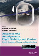
The importance of vertical flight operations for many aircraft cannot be overstated. Among the most compelling justifications, as stated above, are simply associated with the cost of real estate. Indeed, in highly congested urban areas, many vertical flight operations are simply conducted from building rooftops. Compounding the challenges of the high cost of urban real estate is the trouble associated with shallow commercial aircraft glideslopes and the associated large swathes of land that encounter high noise levels as aircraft take off and climb. Figure 12.2 highlights the tremendous cost of real‐estate for urban heliports and airports. Even with the most advanced “Clean Sky” initiatives envisioned, more than £14.6 billion of real estate is affected by the flight corridor [3].

Figure 12.2 Physical noise footprint of real estate impacted at 75 db(a) of representative urban airport (London Heathrow).
If one considers a heliport at the same location with the same passenger density, then a comparison of the real estate affected can be made. Figure 12.3 shows that there is a reduction of two orders of magnitude. The area impacted is indeed so small that it lies within the footprint of the terminal of an equivalent urban airport. As the surrounding buildings are not influenced by the noise footprint of a large‐scale heliport, noise‐based curfews would be eliminated, and flight operations restricted by prevailing winds would be mitigated, if not also eliminated, leading to far more open (and profitable) flight operations. Further, because local communities would be much less significantly impacted, the total number of heliports with similar flight operations could increase dramatically, leading to a large growth in total air passengers.
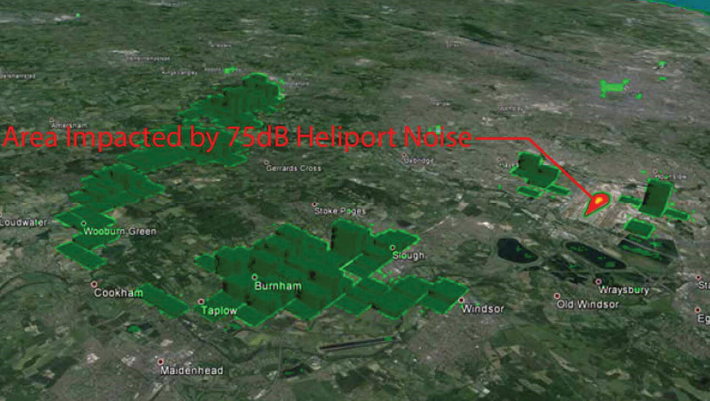
Figure 12.3 Physical noise footprint of real estate impacted at 75 db(A) of representative urban heliport.
12.1.3 Military Vertical Flight Operations
While the case for civil vertical flight operations of high‐speed aircraft is easy to make given the restrictions associated with the congested urban landscape, military flight operations of VTOL‐capable high‐speed aircraft have also been shown to be very useful and are therefore in high demand. Figure 12.4 shows a hovering missile prototype, the XQ‐138 hovering around (at the time), one of the US Army’s Future Combat System prototypes. Although capable of more than an hour of hover endurance, the XQ‐138 could also pop up and dash at speeds in excess of 350 kts TAS.
Figure 12.4 XQ‐138 hovering missile prototype performing battle damage assessment on a US Army Future Combat System prototype; Redstone Arsenal, Alabama, 2002.
Image: Barrett.
During these four months of exercises, it was shown that extremely close inspection of damaged armored assets was not only desirable, but absolutely necessary. Figure 12.5 shows XQ‐138 flight operations as part of live‐fire exercises at Eglin Air Force Base, Florida. Although the T‐60 tank endured a direct hit by a Javelin missile, which produced roughly 15 s of smoke from the vehicle, the penetration hole was extremely small and impossible to pick out from any fixed‐wing asset. Only upon inspection by an XQ‐138 from just 5 m away was it possible to even see the slightly smoking 10‐cm hole, which indicated that the vehicle had indeed been killed. From combat experience in theatres such as Iraq and Afghanistan and extensive XQ‐138 live‐fire testing, it is obvious that overhead observation of targets from hundreds of meters is not sufficient to perform proper battle damage assessment (BDA). Only extremely close inspection of damaged armor can truly assess their ability to engage in further combat. Indeed, the precision approach and landing capabilities of the XQ‐138 was so good that one method of post‐engagement BDA was simply to land on the vehicle, shut the engine down and listen for signs of life within via microphones in the aircraft feet. Certainly no class of conventional takeoff and landing aircraft could even come close to such definitive BDA capabilities.
Similarly, target identification and close‐quarters engagement was shown to be extremely effective with hovering‐missile‐type aircraft. Figure 12.6 shows the XQ‐138 delivering 40‐mm submunitions with 30‐cm accuracy at the McKenna Military Operations in Urban Terrain (MOUT) range in Fort Benning, Georgia, in 2003. Because the basic flight operations of hovering missiles were concretely proven more than a decade ago, the capabilities of such weapon systems has only increased – from organic weapons with organic reach to collocated weapons with strategic reach.

Figure 12.5 XQ‐138 hovering missile prototype performing battle damage assessment on a destroyed soviet‐era T‐60 tank, Eglin Air Force Base, Hellfire Range, Florida, 2002.
Image: Barrett.

Figure 12.6 XQ‐138 hovering missile prototype delivering 40‐mm submunitions against a target from a standing hover, Ft. Benning McKenna MOUT Range, 2003.
Image: Barrett.
12.2 Aircraft Mission Profiles and Sizing Chart Structure
Several of the most important tools that are used by aircraft design engineers are the “Mission Profile” and the “Sizing Chart.” These pictorial representations of the way an aircraft is supposed to fly, under what conditions it must fly, and how big its powerplant and lifting systems are have been employed for nearly a century. Foundational texts such as Roskam’s Airplane Design series [4] employ such tools and reference common industry practice.
Many VTOL aircraft have comparatively nondescript mission profiles, as seen in Figure 12.7 [5]. With vertical ascent and descent, the profiles take the form of a simple box and quite often do not include climb or descent legs with slopes, so as to avoid generation of acoustic footprint sweeps on large swathes of the ground. The mission profile of a common fixed‐wing aircraft – a KC‐135 – can be seen in Figure 12.8. Clearly, because the aircraft is not capable of VTOL flight, its mission is shaped quite differently to that of a VTOL aircraft. Indeed, many conventional takeoff and landing (CTOL) aircraft have quite similarly shaped mission profiles including (especially) features of pronounced climb and descent stages with an extended range in between. However, if one looks at a convertible aircraft (that is, an aircraft that is capable of “converting” from hover‐mode to “dash/airplane” flight modes), then a completely different profile appears.
Figure 12.7 Hovering aircraft straight‐line range mission profile [5].
Figure 12.8 Sample military aircraft (KC‐135) mission profile.
12.2.1 Challenging Mission Profile: VTOL Launch, Recovery, High‐speed Dash
Mission profiles of convertible aircraft often represent some of the most challenging aircraft design problems known in the aerospace industry. Starting with aircraft like the Convair XFY‐1 and Lockheed XFV‐1 Pogo, vertical takeoff and landing flight phases bracket high‐speed dash segments. More precisely, these aircraft hover for takeoff with their noses pointed skyward, then transition by pitching over so that the aircraft deck is mostly horizontal. The aircraft then achieves great speeds during cruise and dash flight modes with this deck level, often greater than a conventional aircraft with the same powerplant, as the wings of convertible aircraft can be much smaller than those of a conventional aircraft. Then as the convertible aircraft come in for landing, the aircraft transitions (or rather, “converts”) again from high speed flight to vertical flight by pulling nose up, entering a hover flight state, eventually touching down like a helicopter. Modern convertible aircraft are found most commonly in the UAV world. Among the several UAVs that are capable of full‐transitioned flight between VTOL segments and high‐speed dash flight phases, the MicroAutonomous Systems (MAS) XQ‐138 is one of the best performers on the market today. At the end of their Micro Aerial Vehicle (MAV) program, a flyoff was held at Quantico, Virginia. MAS’s engineers produced the Lu‐MAV VTOL coleopter MAV. Although the only aircraft that flew without crashing and performed all intended flight functions among the competitors, DARPA chose another team for the following Organic Aerial Vehicle (OAV) program. The MASs team then teamed up with Boeing Future Combat Systems (FCS) supplier ST Aerospace for an RDT&E effort to bring the XQ‐138 to life.
The kickoff meeting of the XQ‐138 program was held in Singapore in July of 2001 and settled on the extremely challenging mission profile shown in Figure 12.9.
Figure 12.9 Mission profile of the MicroAutonomous Systems XQ‐138.
Image: Barrett.
The mission profile above clearly includes performance levels that have never been achieved by subscale aircraft before. In spite of this, the MAS team took the project on and embarked on this most robust program. To achieve this high level of performance, the aircraft was forced to shed total wetted area and profile drag. The problem with eliminating wetted area is that most aircraft depend upon finite‐sized wings to provide lift. These wings, while driving up wetted area, allow the aircraft to takeoff and land at low speeds. Because the XQ‐138 would not depend upon wing area for generation of lift at low speeds (it would necessarily use the rotor in the ducted fan for lift), the wing could essentially be totally eliminated.
12.2.2 Convertible Aircraft: Elimination of Stall Sizing Lines
A standard tool which is used to lay out aircraft is the so‐called “aircraft sizing chart.” This chart typically tracks thrust‐to‐weight ratio (T/W) as a function of wing loading (the amount of weight that can be lofted by a given amount of wing area, W/S). In general, most aircraft are sized by high lift considerations, often associated with takeoff and landing conditions, in addition to cruise, dash, and/or maneuver flight states [6]. The takeoff and landing flight phases necessarily occur at speeds that are so low that flap systems are needed to maintain lift, and yet still large amounts of wing area are often prescribed. Even if one examines a design of a supersonic aircraft [7], then even at relatively moderate wing loadings, the C Lmax considerations of the wing are still critical in laying out the overall size of the wing. Indeed, Figure 12.10 clearly shows that this prize‐winning supersonic aircraft design is firmly defined by landing C Lmax considerations. If an aircraft designer could somehow generate lift at low speeds without the use of a wing, then the very shape of the area of possible solutions on the sizing chart would be dramatically expanded.
12.2.3 Changes in the Aircraft Sizing Chart
Because many convertible aircraft like the XQ‐138 rely upon lift being directly generated from a propulsion device, all of the traditional stall sizing lines essentially disappear from the aircraft sizing chart. In their stead appears a different set of constraints, which are relatively independent from the traditional constraints [7]. These “transition corridors,” rather than being simple functions of wing and power loading, are often mapped out by using wind tunnel and/or flight test data. One of the main reasons why such transition corridors are developed from primarily experimental methods is because the actual aerodynamics of the situation are so complicated that current computational techniques are unable to properly capture the actual behavior of the aircraft. Given the departure of hard and fast stall lines, the design point shown on Figure 12.10 moves dramatically to the right, typically against the stall corners of the transition corridor, which typically increases effective wing loading by factors of three or more. With the considerable increase in wing loading comes a corresponding reduction in wetted area, which in turn allows for much higher speeds throughout all operational altitudes.
Figure 12.10 Example sizing chart for a high‐speed aircraft.
12.3 Convertible Coleopter Design, Wind Tunnel and Flight Testing
Coleopters are not new concepts by any stretch of the imagination. Indeed, the “heyday” of inhabited coleopters occurred in the 1950s, with the SNECMA Coléoptère and the various incarnations of the Hiller VZ‐1 (Figure 12.11) [8]. The basic definition of a coleopter is an aircraft that uses a ducted propulsor, such as a single‐ducted fan, as the primary mechanism for both lift and propulsion in all flight modes. Although there have been a wide range of ducted fan aircraft over the years, comparatively few have successfully flown, with even fewer making full‐transitioned flight and only one having ever been patented and placed into high‐rate serial production.

Figure 12.11 Hiller VZ‐1 Pawnee.
12.3.1 The Roots: Heinkel Wespe and Lerchle
Some of the earliest coleopters were designed during World War II as a series of concepts to skirt problems associated with allied bombing of German runways. Indeed, the Heinkel Lerche (Lark) and Wespe (Wasp) were to be powered by counter‐rotating ducted rotors, takeoff in vertical flight modes, transition, intercept aircraft at high speeds, then return for a vertical landing. The earliest incarnation of the German coleopters was the Heinkel Wespe. Designed at the Vienna branch of the Heinkel Aircraft Company, the tail‐sitting aircraft was touted as being able to takeoff and land without the need for runways [9]. This capability, of course was of great interest to the Luftwaffe, which was dealing with ever‐increasing cratering of their runways and destruction of their cities and military complexes. As the Heinkel designers worked in late 1944 to pitch the Wespe designs to the Luftwaffe, objections were raised about the lack of a wing and the inherent disorientation that pilots would experience as they transitioned from conventional aircraft to an axisymmetric aircraft. At the same time, concerns about the dreaded transition flight phase induced a change of design from a pure ducted‐fan coleopter to one that sported stub wings. This can be seen in the Lerche design shown in Figure 12.12. Fortunately, neither aircraft made it off the drawing boards and the war in Europe concluded long before either could get off a single shot. However, the line of designs continued with punctuated success. Indeed, the postwar Heinkel Aircraft Company even proposed a tail‐sitting aircraft design as late as 1956.

Figure 12.12 Kurt Reiniger’s Lerche concept 1945 [9].
12.3.2 Troubles with Coléoptère and Pogos: Pitchback Instabilities
Throughout the 1950s a wide range of VTOL/VSTOL/STOVL aircraft concepts were tried, at a breakneck pace. For the aerospace historian, this rich “Wild West” period of aircraft design had never really been seen in peacetime, before or since. Although exhilarating in terms of pace of innovation, many corners in analysis and logic of the concepts of operations were clearly cut. The SNECMA Coléoptère represented one of the fastest coleopters to make it to production. As with all of the earlier designs, it was designed to takeoff and land from a very confined space. Lockheed, with their XFV‐1, and Convair, with their XFY‐1, were also exploring the possibility of vertical take‐off aircraft that could then transition via a pitch‐over maneuver and fly out at extremely high speeds.
While these programs each led to full‐scale aircraft prototyping and flight testing, several profound problems surfaced. The first and most obvious of these involved the human factors. As pilots climbed aboard these aircraft, their downward vision was obscured. This obscuration by objects like “the pilot’s nose” meant often that only one eye at a time could accurately see the ground approaching. Accordingly, the pilots lost parallax vision, which in turn compromised depth perception. Given that the delicate tail fins were just in front of comparatively light landing gear, the risk of empennage damage during takeoff and landing was pronounced and often led to damaged aircraft components.
Compounding the human factors, troubles associated with near‐ground flight operations also included the blanking of the control surfaces due to the presence of a large ground‐effect‐induced recirculation donut. This aerodynamic structure, which necessarily formed as the aircraft approached the ground plane, would reduce the dynamic pressure across the empennage to nearly zero. As a result, just when the pilots needed the most amount of control authority, they had the least. Of course, given ever‐more robust landing gear, designers could simply have pilots “zoom” for a takeoff and “plant it” for a landing, but out‐of‐ground‐effect (OGE) freeflight also posed great challenges.
These nontrivial challenges were observed first in the Hiller VZ‐1 Pawnee flight tests and later in the punctuated coleopter designs, which have regularly come around every 20–30 years after those early aircraft. To understand these OGE problems, one simply needs to reach back a bit into time, to a proposal submitted to DARPA in 2001. At the time, two main competing concepts were being pitched to the Federal Government by a pair of contractors. One contractor, Allied Aerospace Industries, had no experience with vertical‐flight ducted‐fan aircraft; the other contractor, Lutronix Corp. of Del Mar, CA had more than 1800 successful coleopter flights under its belt over the preceding three years. As a result of such extensive knowledge of how coleopters behave, the Lutronix Team explained to DARPA how coleopters suffer tremendously from pitchback instabilities and necessary excessive control force application during these atmospheric conditions. Figure 12.13 is extracted from their proposal.
Figure 12.13 Fundamentals of Coleopter pitchback instability [10, 11].
Although the Lutronix team worked very hard to warn DARPA of impending doom should they choose to fund such a configuration, DARPA sponsored it anyway. The most public demonstration of this catastrophic pitchback instability occurred in September of 2003 as the resulting iSTAR vehicle was hit by light crosswinds and proceeded to catastrophically crash in front of an assembled crowd of military commanders and press at Fort Eustis, Virginia. As Gary Downs, the director of Allied UAV Systems said following the catastrophic crash, “We didn’t have the control authority needed for the prevailing conditions.” [11]
The assessment of the crash included an examination of the forward‐flight capabilities. Downs explained the “newly discovered” pitchback instabilities further to the press: “Unfortunately, this effect limited the forward speed to a mere 26 kph (16 mph) and caused erratic handling in windy conditions.” So although the effect was well understood, predicted and reported to funding agencies long before the first flight test, such designs still come around at regular intervals and still face the same issues, which are generated by the fundamental physics of the configuration.
12.3.3 Control Power – The Necessity for Proper Control Effector Coupling
Although conventional coleopters like the Coléoptère, VZ‐1 and iSTAR all suffer from pitchback issues and lack of control authority, not all coleopter designs are inhibited by this characteristic. Curiously enough, Reiniger and Schulz of the Heinkel Design bureau both recognized this issue all the way back in 1944 and laid out designs that specifically counter this tendency. This was done by placing the aerodynamic center of the tail of the Heinkel Wespe (Figure 12.14), several mean geometric wing chords downstream from the aircraft center of gravity, and it was seen as a critical design feature. Only is this way was it possible to maintain acceptable pitch and yaw control authority. Given that as of 1944 the Heinkel Design Bureau had extensive experience with real, inhabited, high performance aircraft design, they understood exactly how to lay such things out.

Figure 12.14 Heinkel Lerche with tail control effector distance highlighted.
While the Heinkel design engineers were far from clairvoyant, they understood aircraft design and fundamental physics very well. The aircraft designers of Lutronix Corporation of Del Mar, CA called upon these early historical lessons as they laid out the designs of the Lutronix LuMAV family of aircraft, starting in 1994. Although these aircraft would become the DoD’s first MAVs, they were based on some very old design principles. Figure 12.15 shows the earliest freeflight version of the LuMAV family of hovering coleopters. The reader will notice that unlike the Heinkel Lerche and Wespe, the LuMAV flew without a nose assembly. Because the mission specification and profile called for only low‐speed hovering flight, the aircraft was not designed for transition (as was the Lerchle and Wespe). Although not specifically designed for high‐speed forward flight, it was shown that the aircraft could still translate at more than twice the speed of the iSTAR and could handle gusts that were so severe that the local Coast Guard HH‐65 fleet of helicopters were grounded during flight testing at MacDill Air Force Base, Florida in 1998. The general design consideration that evolved from the experiences with the LuMAV program was that the aerodynamic centers of the empennage control effectors should be approximately one rotor diameter or more away from the aircraft’s center of gravity.
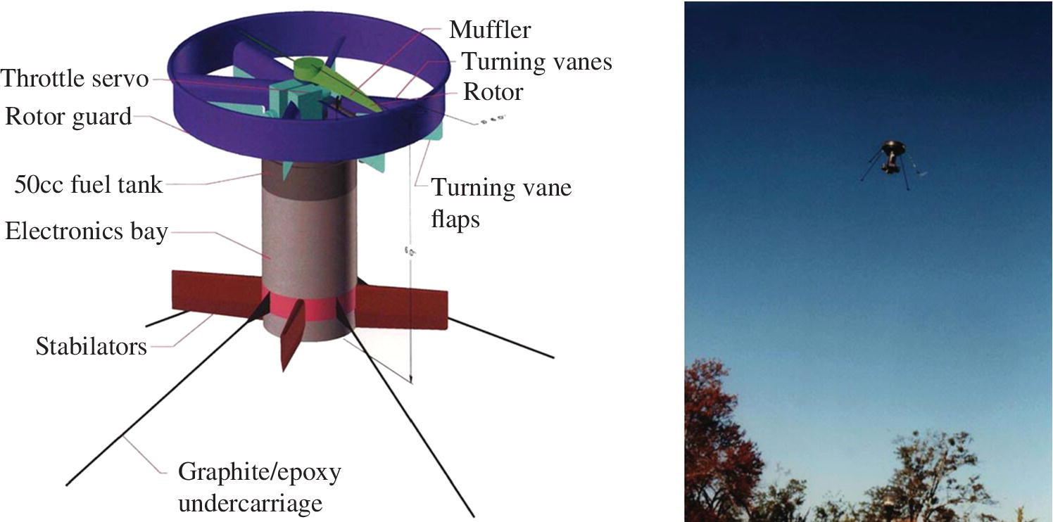
Figure 12.15 Lutronix LuMAV hovering coleopter for the DoD Counterdrug Technology Office.
As DARPA chose the iSTAR configuration, fortunately, the Lutronix team managed to make contact with the Boeing Future Combat Systems team. This group included a number of players from around the world, including Singapore Technologies Aerospace (ST Aero). Because the Lutronix team, arguably, had at the time the best uninhabited coleopter designs in the world, ST Aero signed an agreement to partner with Lutronix Corp. so as to bring take the coleopter designs out of the hover state and towards full‐transitioned flight modes, thus realizing their potential. So began the RDT&E effort of the XQ‐138 Convertible Coleopter family of aircraft.
12.3.4 High‐performance Coleopter Flight Testing: Control Authority and the Establishment of the Transition Corridor
Starting with handshakes, mission specification and profiles in July of 2001, the Lutronix team was absorbed into the new company, MASs. The team worked at a breakneck pace in the Fall of 2001 with many members of the team logging well over 100 work hours/week. The result of this “wartime pace” of RDT&E effort would be a first flight date just 11 weeks after first start of funding. Although the team was well aware of the “one rotor diameter” separation between the aircraft center of gravity and the aerodynamic center of the empennage effector, the team laid out a very special empennage configuration, which called upon the highest normal force gradient effectors known in the aerospace industry. These “grid fins” were typically used on Soviet and Russian missiles and rockets exactly because they have such tremendous normal force gradients.
The chief designer of the XQ‐138, as it happened, was also instrumental in reverse‐engineering the grid‐fins for the US government and was well aware of how they work, how to size them, where and when to employ them. Indeed, they are critical features distinguishing the XQ‐138 family of aircraft from other coleopters. In short, the crux of US Patent 6,502,787 [12] was that the fuselage, powerplant and propulsion core of the Heinkel Wespe and Lerche were fitted with a grid‐fin assembly akin to that of the Russian AA‐12. as shown in Figure 12.16. In spite of the best efforts and analysis techniques of the XQ‐138 design team, the first three flight tests in December of 2001 yielded dangerously low levels of control effectiveness. So although more than a half‐century had passed since Reiniger and his team at Heinkel had first laid out the Wespe, his lessons still rang true: More control effectiveness was needed, spacing the empennage roughly 1 rotor diameter from the aircraft center of gravity. Accordingly, the first significant geometric change that was made to the earliest variant of the XQ‐138 was to grow the empennage length by one third of a rotor diameter. To this day, nearly all variants of the XQ‐138 still fly with the volume coefficient established by the Heinkel team in 1944.
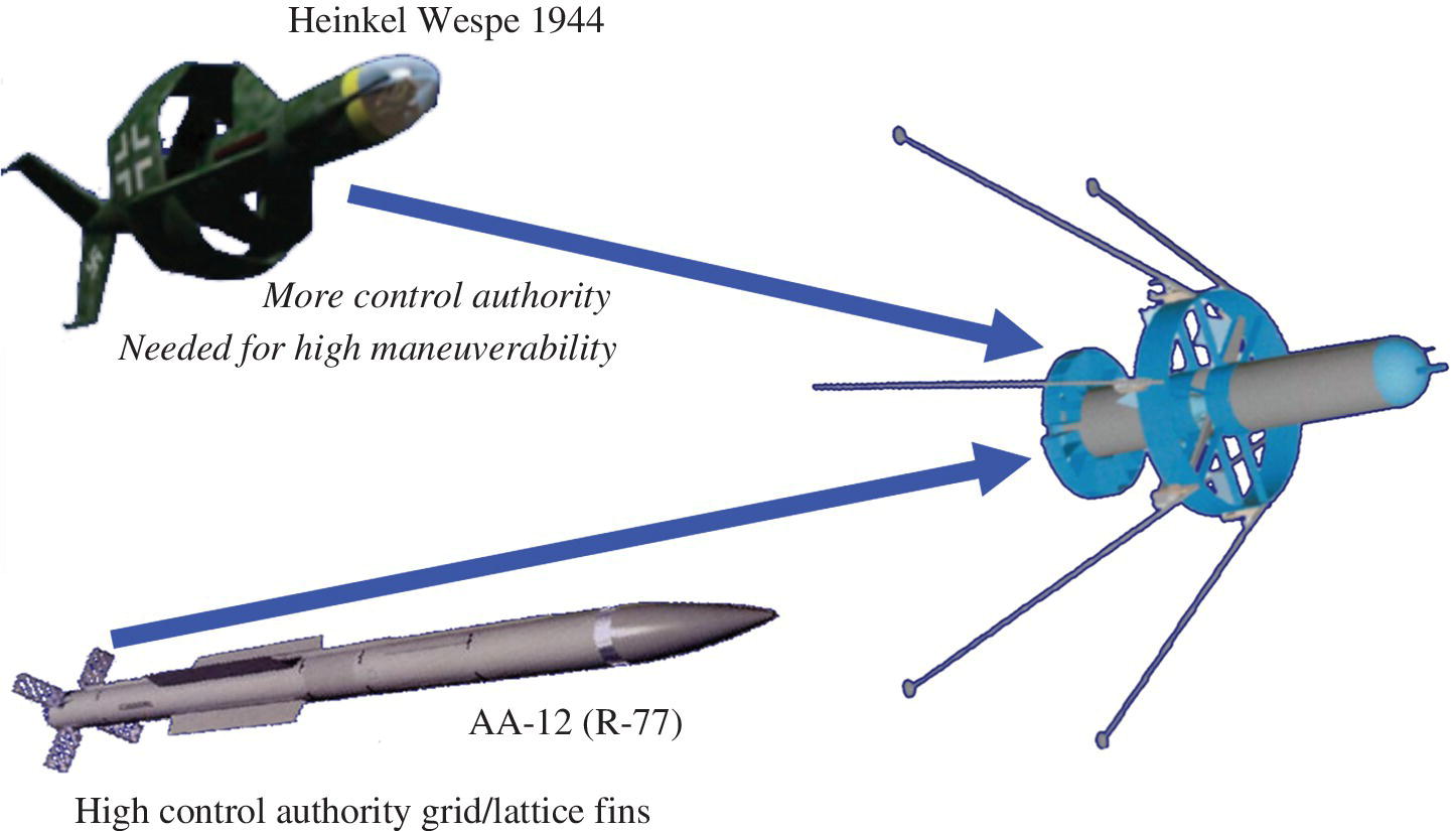
Figure 12.16 Heinkel Wespe and Russian AA‐12 design feature contributions to the XQ‐138 convertible coleopter.

Figure 12.17 High‐speed variant of the XQ‐138.
The result of such high levels of control authority was simply astounding. By January of 2002, the MASs team had achieved full conversions from vertical to horizontal flight modes. As part of the preparations for Asia Aerospace 2002, the design team had several of the aircraft undergo full transitions at 38 °C and 100% humidity while breaking speeds of more than 100 kts. These top speeds would eventually reach more than 350 kts with high‐speed variable‐pitch rotors and faired boattail speed kits (Figure 12.17). In short, the performance of the XQ‐138 was nothing short of stellar: Hover times in excess of an hour, high‐speed dash at up to 350 kts for nearly an hour.
Not surprisingly, in 2004, ST Aerospace purchased the exclusive rights to the entire line of aircraft related to the XQ‐138 and took it into serial production under the trade name of “The ST Aero Fantail.” To date, the ST Aero Fantail is thought by many to be the only fully convertible coleopter ever to have achieved high‐rate production on the commercial market.
As part of the RDT&E effort, the MASs‐ST Aero team also flew more than a thousand flight tests on the XQ‐138 and its follow‐on variants. During flight tests, some extremely dangerous flight modes were explored. The most unstable and dangerous of these included high‐rate tail slides and high‐speed pull‐ups. On no less than three occasions, aircraft departed the flight path, tumbling uncontrollably end over end, eventually crashing in the swamps next to the Strait of Johor. A montage of a flight path departure is shown in Figure 12.18.
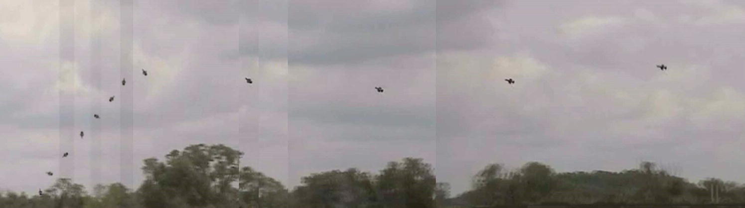
Figure 12.18 Montage of XQ‐138 flight path departure at 150 kts, 5.9 g turning pullup.
Clearly from Figure 12.18, the aircraft departure was violent and lead to a complete hull loss. As the flight test data was analyzed, it was determined that a violent flow‐separation pitch‐up instability was induced by flow separation off the aircraft forward fuselage, blanking part of the flow into the propulsor. So in spite of the high levels of control authority available from the gridfin assembly, there are clearly limits. Similarly, flight path departures were also experienced in comparatively low‐speed vertical descents. These effectively put the empennage right in the middle of the vortex generated in the vortex‐ring state (similar to what is experienced by helicopters). With experience, pilots figured out that quite often extremely high power settings can be used to increase the dynamic pressures over the empennage, which in turn restores control power and can overcome these departure dynamics. Accordingly, nearly fifty flights were conducted at the edges of the flight envelope, resulting in full‐flight path departures, but with all but six recovered by pilots.
A general rule combining transition and departure concerns evolved from these flight tests. That is, if steady‐state flight could be achieved in a trimmed state at a given angle of attack and total flight speed, then any power settings higher than those required for steady state flight would most often lead to recovery from departure. Conversely, it was often observed that lower power settings at high angles of attack almost always led to (often catastrophic) stability and control issues.
Flight testing was conducted between Auburn, Alabama, Eglin AFB, Florida, Ft. Benning, Georgia and Singapore at altitudes ranging from sea level through 500‐m AGL. So as to discover the edge of the flight envelope, over a span of three years (2002–2005) the aircraft was regularly flown “to its limits.” Figure 12.19 shows the results of these flight tests. A very clearly defined departure boundary was established; above the boundary, the angle of attack was deemed to be so high that in steady‐state flight the aircraft would depart, mostly due to flow separation on the nose being ingested into the rotor guard. Below the line, with positive forward flight speeds, both stability and control was generally assured. It should be noted that as the aircraft would descend in a “tail slide,” various helicopter‐related instabilities would present themselves. The reader will see three red cross‐marks left of the zero forward flight speed line at comparatively low angles of attack. The reader will note that the aircraft in these flight conditions is moving backwards through the sky with slight rearward motions at speeds beyond 20 kts. In these flight states a recirculation zone forms around the grid fins, which nullifies longitudinal control authority.

Figure 12.19 XQ‐138HS flight test data showing steady state and departed flight boundary.
Clearly, Figure 12.19 forms the kernel of the flight director boundaries, which set the limits of the aircraft during transition and forward flight. The reader will see that departures were even noted at high forward flight speeds. These generally corresponded to extremely high‐g pullups being executed, again inducing flow separation off the nose, causing rotor blanking and high pitching moments.
12.4 Future: Convertible QuadCopter Design and Flight Testing
Although coleopters are among the leading classes of aircraft which are capable of full body hover‐to‐dash conversions, there are several other types of aircraft that are coming to market which can also convert and are making inroads into markets such as those for subscale UAVs and toys. Figure 12.20 shows Edissey, LLC’s Quadrocket family of convertible UAVs. As this chapter is being penned, the aircraft and its designers are working to set class speed records.
Figure 12.20 Edissey convertible “Quadrocket” UAV.
12.5 The Extreme: Hover‐to‐Supersonic Dash Aircraft
The major drivers for conversion, as stated earlier, are clearly related to vertical flight operations during takeoff and landing coupled with extremely high dash speeds. If one takes this to the extreme, then the top speeds push well into the supersonic. To achieve this, a ducted fan geometry is not a suitable solution. Rather, relying upon folding rotors that can become wings is a far more suitable option. From extensive flight testing, it is clear that there are currently no practical upper bounds on the size of the aircraft under consideration.
Rather, it is perfectly possible that such coleopters could be stretched to comparatively large sizes to do all kinds of missions. If one examines Figure 12.21, then one can see that aircraft in excess of 10 m of fuselage length are more than feasible. If one looks only at a comparatively small aircraft, just 2 m in length (as shown in the design point on the chart), then many useful missions could be accomplished. If the aircraft were to be refueled in flight (as shown in Figure 12.22), then the aircraft could stay airborne for extremely long periods of time. Because the XQ‐138 first demonstrated that aircraft of this class could be quite handily armed with small arms well over a decade ago, it is perfectly possible that the concept of collocated close air support could be realized in the very near term. If one considers the fastest “time in contact” response that the military generally works with when considering close air support, the lower bound is 5 min. If one uses this number in laying out operations of current interest, then it can be seen that just 9 tracks are needed for Iraq and 10 are required for full coverage in Afghanistan. Other critical missions for such aircraft include SOF support as well as counter‐piracy. So clearly such aircraft could be of tremendous utility to military planners if they would only realize that such aircraft are just an RDT&E effort away.

Figure 12.21 Tactical and strategic coleopter designs.
Figure 12.22 2‐m coleopter refueling in flight.

Figure 12.23 2‐m coleopter tracks for 5‐min time‐in‐contact reponse collocated close air support.
Figure 12.24 Supersonic hovering aerial vehicle [13, 14].

Figure 12.25 Counterpiracy coverage area of a 1000‐lb maximum gross weight at takeoff supersonic hovering aerial vehicle.
If one stretches the capabilities of the convertible aircraft deep into high‐performance levels, then it is easy to see that via clever arrangements, a supersonic variant of the aircraft appears. The “Supersonic Hovering Aerial Vehicle” (SHAV) is one way to achieve efficient, long‐endurance hover capability while maintaining efficient supersonic dash capability. The aircraft would be built around a variable‐cycle turboshaft engine, which is capable of declutching from the rotor system, allowing the propulsion core to augment thrust in the high subsonic through the low supersonic range. A variable engine cycle is more than feasible. Indeed, the J58 propulsion core has been flown for more than a half‐century in the SR‐71. Figure 12.24 shows one configuration that allows for this combined hover and dash capability. The folding blade‐wings have such high fineness ratios that wave drag is minimized throughout the flight envelope. If such an aircraft were to undergo full‐scale development then the 5‐min TIC response figures of Figure 12.23 collapse from 9 and 11 tracks for full‐country coverage to coverage of the entire country from a single base. If counterpiracy missions are examined, then large swathes of the Indian Ocean can be covered from a single surface vessel with the horizontal deck space limitations of a corvette or cruiser, as shown in Figure 12.25. It is obvious that such tremendous performance significantly outstrips the capabilities of regular navies of today. Because the technologies which are fundamentally enabling to aircraft like the SHAV are mature and ready for integration, it is simply a matter of time until aircraft like these are integrated into armed forces.
References
- 1 Barrett, R., “Convertible aircraft,” Short Course offered through Barrett Aerospace Technologies, Lawrence, Kansas, USA, 2009.
- 2 Charnov, B.H. From Autogiro to Gyroplane: The Amazing Survival of an Aviation Technology, Westport, Connecticut: Praeger Publishers, 2003.
- 3 Albert, M., Cadot‐Burillet, D., and Williams, A., “Integration of mission trajectory management functions into clean skytechnology evaluation process,” Paper no. 100, Proceedings of the 5th Challenges in European Airspace (CEAS) Conference, 7–11 September 2015, Technical University of Delft, Holland.
- 4 Roskam, J., Airplane Design, Volumes I–VIII, published by Design and Research Corporation, Lawrence, Kansas 2014.
- 5 Barrett, R.M., “A pattern of mishandling of patentable technology at Auburn University: A review and response to Auburn University's Office of the Vice President for Research,” BAT Technical Report, Vol. 1, No. 1, Oct. 2003.
- 6 Barrett, R., “Typical refueling aircraft mission profile,” AE 521 Aerospace Design I Lecture Manual, p. 147, University of Kansas, Lawrence, Kansas USA 2016.
- 7 Brown, M., Van de Kerkhof, K., Klein, R., et al., “The supersonic multi‐utility aeroelastic reconfigurable test‐bed,” Winner of the American Institute of Aeronautics and Astronautics Graduate Aircraft Design Competition, The Technical University of Delft, Delft, Holland, 2014.
- 8 Anon., “Flight test photo of the Hiller VZ‐1 Pawnee,” Smithsonian Institution, Washington, DC, July 2015.
- 9 Reiniger, K., “Heinkel Lerche I design drawing,” Heinkel Flugtechnische Werke (VFW), 24 February 1945.
- 10 Barrett, R., “Typical aircraft sizing chart including STAMPED data overlay,” AE 721 Advanced Aerospace Design I Lecture Manual, p. 169, University of Kansas, Lawrence, Kansas USA 2016.
- 11 Barrett, R., “Coleopter configured aircraft,” AE 781 Rotary‐Wing Aerodynamics Lecture Manual, p. 118, University of Kansas, Lawrence, Kansas USA 2016.
- 12 Barrett, R., “Convertible vertical take‐off and landing miniature aerial vehicle,” 6,502,787, US Utility Patent, February 22, 2002.
- 13 Barrett, R., Bramlette, R., and Honea, R., “Convertible Aerial Vehicle,” US Patent Invention Disclosure Filed 24 August 2014.
- 14 Barrett, R., “Supersonic hovering air vehicle,” US Patent Application US 9004393, October 2010.