
Lesson 8. Working with Mixer Channels
At the heart of any mixer is the channel. All signals are routed through channels, modified by effects processing, and ultimately brought together in a mix.
In Logic, mixer channels are based directly on objects in the Logic Environment, each channel dedicated to a specific type: MIDI, audio, or software instrument. These channels are accessed via Logic’s integrated Mixer, which shows them in an organized display.
Each channel offers a set of controls for working with the signal throughput. Among these controls are inserts for applying effects processing to the signal path, and sends for feeding a controlled amount of the signal to another Mixer channel.
In this lesson you will use the Mixer to efficiently view and access the Mixer channels and apply effects processing in the signal chain. In addition, you will manipulate the order and placement of plug-ins in Logic’s Mixer.
Using the Mixer
The Mixer has three display modes that access the channels of a mix: Single view, Arrange view, and All view. Understanding how the three differ will help you navigate through your mix efficiently.
In this first exercise, you will open the project file to use throughout the lesson.
- Choose File > Open.
- In the file selector box, go to Music > Logic 8_BTB_Files > Lessons and open 08_I Was Raised_Start.logic.
- Play the project to familiarize yourself with the material, clicking the Stop button when you are finished.
Using Arrange View
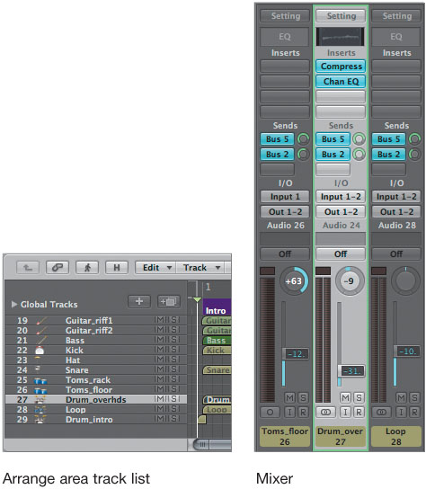
The Mixer’s Arrange view is often referred to as an adaptive mixer. In this display mode, Logic creates a Mixer setup adapted from the Arrange area’s track list, reflecting aspects such as track order, track names, and assigned colors. The Mixer’s Arrange view will reflect the Arrange area’s track list, even when new tracks are created and reordered.
Arrange view will probably be the view you use most often when mixing, as it allows you to focus on those elements that are directly involved with the project’s arrangement.
With the project open, you can observe firsthand the relationship between the Arrange area and the Mixer’s Arrange view by rearranging the track order for a more ergonomic mixing setup.
- Open Screenset 2.
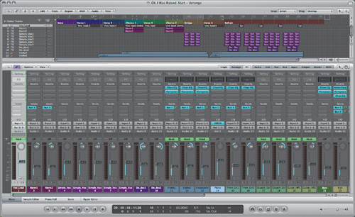
This screenset contains an open Mixer with a small Arrange area (based on the template you created in Lesson 1, “Speeding Up Your Workflow”).
- In the Arrange area, use the vertical scroll arrows at the far right or the up and down arrow keys on your keyboard to examine the tracks in the arrangement.
Note
If you are using a smaller screen resolution than 1140 × 900, it is possible that the vertical scroll arrows will be hidden from view. If this is the case, use the Up and Down Arrows to scroll through the track list instead.
There are 29 tracks displayed vertically in the track list.
- In the Mixer, use the scroller to examine the channels used for the project.
This is a fairly large session, with 37 channel strips displayed side by side. Notice that the first 29 channel strips correspond to the tracks listed in the Arrange area’s track list, in both order and number.
- In the Mixer, try selecting different tracks by clicking the name at the bottom of each channel strip.
When a channel is selected, it is highlighted with a light green border. Note that the same track is highlighted in the Arrange area, which automatically scrolls to display the track selected in the Mixer.
- In the track list of the Arrange area, try selecting other tracks.
When a track is selected in the Arrange area’s track list, the Mixer automatically scrolls to display the corresponding channel.
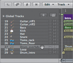
- In the Mixer, select track 25, the drum overheads channel (Drum_overhds).
Note that this channel is located between the Snare and Toms_rack channels. It would be more conveniently located in the Mixer next to the other stereo drum tracks (Drum_intro and Loop).
You can move the track in the Arrange area while observing the changes in the Mixer.
- In the Arrange area’s track list, drag the track downward, dropping it after the Toms_floor track.
The track order changes in both the Arrange area and the Mixer, and the Drum_overhds track is inserted between the Toms_floor and Loop tracks.
Using the Channel Strip Filters
The channel strip filter buttons, located at the upper-right side of the Mixer, define the types of channels displayed in the Mixer. They can be selected singly or in combination. When the filter buttons are used in Arrange view, the display will show only the tracks in the Arrange area that are of the selected types defined by the filter buttons. By default, all the filter buttons are selected, thereby displaying every type of channel available in a given view.
- Click the Audio channel strip filter button to turn it off.
All audio channels in the arrangement are hidden, leaving a single instrument channel, plus the aux, output, and master channels used by the Arrange area tracks.
- Click the Audio button again.
All channel types are now active, and the complete arrangement is visible.
Using All View
The Mixer’s All view displays all the channels available in the project. All view has a direct connection to Logic’s Environment; a channel has to exist in the Environment to be displayed in All view.
Since the tracks displayed in All view correspond to Environment channels and not to tracks in the Arrange area, you can use this view mode to look at channels—such as output and master channels—that are not otherwise contained in your arrangement. As in Arrange view, channels in All view are displayed via the channel strip filter buttons. The channel strip filter selections made for the Arrange and All views are independent, and they remain intact even when you toggle between the display modes.
Rather than use All view to display multiple (or all) types of channels, it is most useful to dedicate All view to a single type of channel, such as output channels. All view then becomes an “alternative” Mixer that provides quick access to a frequently used channel type in a mix.
In this exercise, you will set up All view as a dedicated output mixer.
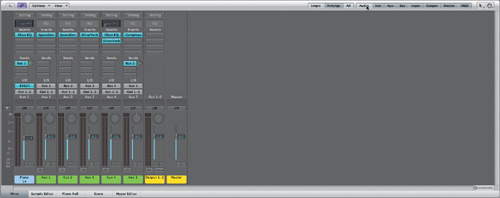
- In the Mixer menu bar, click the All button.
By default, all filter buttons are turned on, displaying all channel types available in the project’s Environment. To view only channels of a specific type, you need to disable all channel strip filter buttons for channels that you do not wish to view. This can be time consuming, but Logic supplies a single-action shortcut.
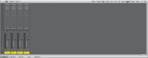
- In the menu bar, Option-click the Output button.
All channels disappear and are replaced by the output channels (four stereo channels) available to the project.
Note
You need to have an audio interface with at least eight outputs for the output channels to appear active (having a fader, pan control, inserts, and so on). Otherwise, the output channels will appear labeled but blank.
Option-clicking a channel strip filter button displays only the selected channel type. You can add other channel types to the view by clicking (without Option) additional filter buttons.
- Click the Master button to turn it on.
The master channel is added to the mixer.
- Click the Arrange and All buttons to toggle between the view of the output and master channels (All view) and the tracks used in the arrangement (Arrange view).
Notice that the display modes remember the channel filter settings you last assigned, even when switching between Arrange view and All view.
This setup enables you to conveniently access individual outputs on your audio interface as you adjust volume levels, apply signal processing, or perform bounces.
Using Single View
Single view essentially limits the Mixer display to a single isolated channel and its signal path. This offers an effective way to trace the signal flow from track to output, including all send destinations (aux channels). While Single view can be left enabled as you select source channels via the Arrange area’s track list, it makes more sense to treat it as a temporary view state that can be toggled on and off while you’re mixing in the other view modes. This allows you to quickly focus in on, and make adjustments to, a single channel’s signal flow, then return to working on the total mix.
- If Arrange view is not already selected, click the Arrange button in the menu bar.
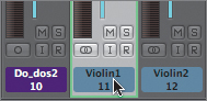
- Click the Violin1 channel strip (track 11).
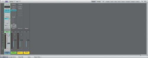
- Click the Single button.
The complete signal flow stemming from the Violin1 channel is displayed, including the send destination (Aux 1) and the output and master channels.
- Click the Arrange button to return to the overall mix.
Using Insert Effects
Processors such as equalizers, de-essers, and compressors are commonplace in the majority of mixing scenarios, most often inserted directly into a channel’s signal path. Logic offers many flavors of equalization and dynamics processing in the form of individual plug-ins, each suited for specific tasks and functions.
In this exercise, you will use Logic’s Channel EQ, DeEsser, and Compressor plug-ins to process the lead vocal track, exploring the unique properties offered by each plug-in.
- In the Mixer, select the Vox_Lead channel (track 1).
- Click the Vox_Lead channel’s Solo button.
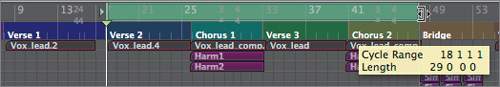
- Press Control–Command–Right Arrow/Left Arrow (Go to Next/Previous Marker) to locate the playhead at Verse 2.
- In the Transport bar, click the Cycle button to turn on Cycle mode.
- In the Arrange area, drag the cycle area’s right border to the right so that it encompasses the Chorus 1, Verse 3, and Chorus 2 sections.
This will enable you to have a varied selection of vocal parts.
- Play the project, listening to the soloed lead vocal to get an idea of what you will be working with.
- Stop the project playback.
Using the Channel EQ
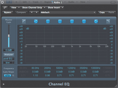
The Channel EQ, part of Logic’s suite of equalizers, is the default equalizer for use in channels. This high-quality plug-in offers eight frequency bands, with an integrated Fast Fourier Transform (FFT) analyzer and an intuitive graphical interface.
- In the Vox_Lead channel (track 1) at the far left of the Mixer, double-click the EQ area.
The channel’s Channel EQ plug-in opens.
Note
When you double-click the EQ area, the Channel EQ will instantiate on the first available Insert slot. The Channel EQ can also be instantiated on the Insert slot of your choice if you click the Insert slot and choose EQ > Channel EQ > Stereo/Mono/Multi Mono (depending on the channel format) from the pop-up menu.
You can start by using the built-in Analyzer to look at the vocal signal.
- Play the project.
- While the project is playing, click the Analyzer button (at the left of the Channel EQ window).
The signal’s frequency content appears in the central EQ display, represented by an animated line that updates in real time to reflect the signal’s frequency curve.
The Channel EQ window is multifunctional. The signal’s frequency curve is continually displayed, and you are able to make changes by graphically drawing in the EQ curve. This greatly helps to identify and correct problem spots in the signal.
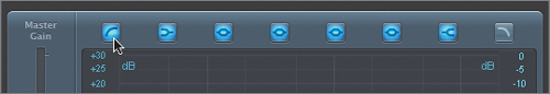
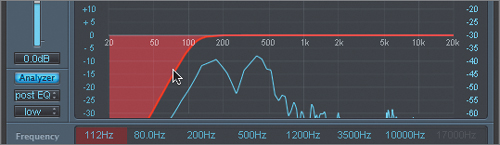
- Click the first band button to turn on the low-cut filter.
A gray frequency curve is shown at the far left of the EQ graphic display, representing the range of the low-cut filter.
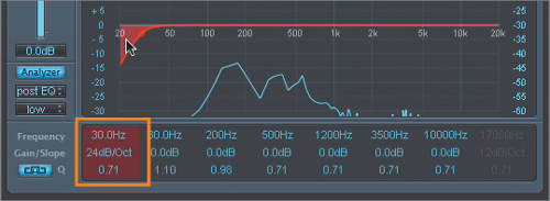
- Position the pointer over the gray curve.
The band changes to a light red color, as does the numerical display for the band, located just below the curve in the Parameter section.
- Drag the red EQ curve to the right, until the Frequency field in the Parameter section reads 112Hz.
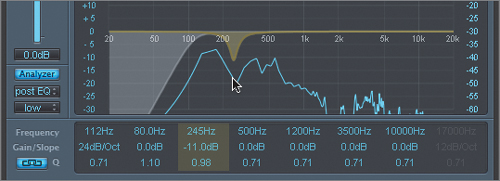
- In the EQ graphic display, position your pointer just below the 0 dB line at the 200 Hz range.
A yellow dot, called the pivot point, appears at the pointer position. The corresponding numerical display within the Parameter section is also highlighted in yellow, indicating the band you have chosen (the third band from the left).
- With the yellow pivot point and band illuminated, drag the area just below the 0 dB line down and slightly to the right while watching the numerical display in the Parameter section. Release the mouse button when you reach a Frequency setting of 245 Hz and a Gain setting of −11.0 dB.
Tip
You can also create or adjust the EQ curve by dragging any number in the Parameter section for the corresponding band.
A parametric EQ curve is created, with the center of the band at the pointer position.
This creates a substantial frequency cut in the 245 Hz range, but its bandwidth is a bit too narrow. You can change the bandwidth, or Q, by dragging the pivot point up to tighten the bandwidth and dragging it down to broaden the bandwidth.
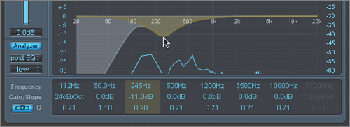
- Drag the dot (pivot point) down to broaden the bandwidth until you reach a Q value of 0.20.
Note
When instantiated, the Channel EQ activates Gain-Q coupling by default. Represented by a Link button in the lower-left corner, Gain-Q coupling automatically adjusts the bandwidth (Q) when you raise and lower the gain for an EQ band. This preserves the perceived bandwidth of the bell-shaped parametric curve. You can disable this function by clicking the Link button.
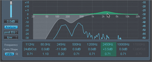
- In the graphic display, position your pointer over the 3500 Hz range.
A green pivot point appears at 3500 Hz, and the corresponding numerical display is highlighted in green.
- Using the techniques that you just learned, create a Frequency setting of 2450 Hz, a Gain setting of +3.5 dB, and a Q setting of 0.71.
A parametric EQ curve is created, with the center of the band at the pointer’s position.
Tip
You can return each bandwidth component to its default values by Option-clicking the corresponding numerical setting within the Parameter section.
You now have an EQ curve that enhances the lead voice.
- Click the Pre/Post EQ button (on the left below the Analyzer button), changing the display setting of the Analyzer to “pre EQ.”
By toggling between the two display modes, you can compare the frequency spectrum with and without the EQ curve applied.
- Click the Analyzer button, disabling the frequency display.
- Stop the project playback.
- Close the Channel EQ window.

Using the DeEsser
The lead vocal now sounds considerably less muddy, but it also has noticeable sibilance. You can utilize Logic’s DeEsser processor to detect and compress the offending frequency, reducing the sibilance of the vocal.
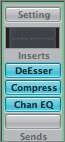
- Click the second Insert slot on the Vox_Lead channel, and choose Dynamics > DeEsser > Mono from the pop-up menu.
Tip
You can also click a plug-in name in the pop-up menu to insert it, rather than choosing the format (mono, stereo, or 5.1) within the subsequent menu. When doing so, Logic automatically selects the format that best matches the channel.
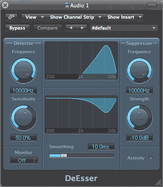
The DeEsser plug-in opens.
The DeEsser plug-in is a compressor that rejects a specific frequency band for as long as a threshold level is exceeded. It accomplishes this by locating the problem frequency with the Detector and reducing the same frequency band (or a different band) with the Suppressor.
Logic’s DeEsser has an extremely flexible monitoring system that allows you to listen to various functions of the DeEsser at work. This enables you to home in on the offending band quickly and easily.
- Play the project.
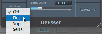
- While the project is playing, click the Monitor pop-up menu (the default is Off) at the lower-left corner of the plug-in interface and choose Det. (for Detector).
The sound output immediately changes because you’re now monitoring the signal through the Detector’s frequency range. You will use this to help identify the offending frequency of the sibilance.
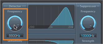
- Drag the Detector Frequency knob, listening to the vocal as the frequency band sweeps.
- Stop dragging the Detector Frequency knob when you hear the “sizzling” sounds emphasized, at about 8800 Hz.
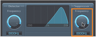
Now that you’ve set the frequency band that will trigger the DeEsser, you can set the Suppressor to reduce the same band (most common) or to suppress a different frequency band when the DeEsser is active.
- Drag the Suppressor Frequency knob, matching the Detector Frequency setting of 8800 Hz.
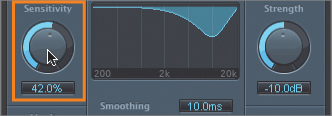
After isolating the frequency of the sibilance, you’re ready to set the threshold at which gain reduction is applied. You can do this most effectively by monitoring the Detector Sensitivity knob, which dictates the threshold at which the DeEsser begins to work.
- Click the Monitor pop-up menu and choose Sens. (for Sensitivity).
Because the Sensitivity control occurs after the Detector Frequency control within the DeEsser’s internal signal flow, the monitored sound consists only of audio in the selected band, with enough gain to get through the Sensitivity circuit. The result is short sibilance bursts. With this Monitor mode, you are trying to listen only to the offending sound.
- Drag the Sensitivity knob down, reducing its value to 42.0%.
You should hear only sibilance.
- Click the Monitor pop-up menu and choose Off.
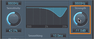
The sound changes because you’re monitoring through the entire DeEsser audio chain. Now that you have successfully isolated the offending frequency, you’re ready to apply gain reduction by using the Strength knob.
- Drag the Strength knob up to a value of −11.0 dB.
This should reduce the isolated frequency without compromising the full bandwidth signal.
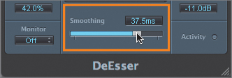
- Drag the Smoothing slider to the right until you reach a value of 37.5 ms.
This smoothes the attack and release of the DeEsser, creating a subtler effect.
- While the project is playing, observe the Activity light at the lower right of the plug-in.
This indicates when the DeEsser is actively clamping down on the offending frequency.
- Close the DeEsser window.
- Stop the project playback.
Using the Compressor
Logic’s Compressor plug-in provides effective dynamic control and is particularly well suited for processing vocals. By inserting the Compressor into the signal chain after the Channel EQ and DeEsser, you can tighten up the dynamics of the corrected sound, producing a fuller, more robust result.
- Click the third Insert slot of the Vox_Lead channel and choose Dynamics > Compressor > Mono from the pop-up menu.
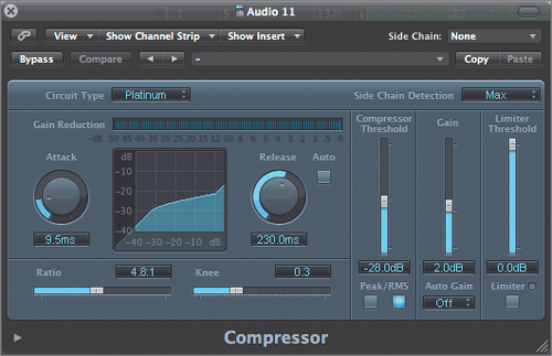
The Compressor plug-in window appears.
The Compressor plug-in is a multimode dynamic processor with a built-in side chain and limiter. New to Logic Pro 8 are multiple circuit types based on various gain-control elements inspired by compressor designs both vintage and modern. From colored to transparent sounds, the Compressor offers processing that is well suited to the diverse mixing needs of modern production.
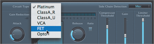
For the Vox_Lead track, a Field Effect Transistor (FET) compressor circuit is a good choice. A FET compressor is often used on vocals for its ability to respond quickly to a signal and create a clean and punchy sound.
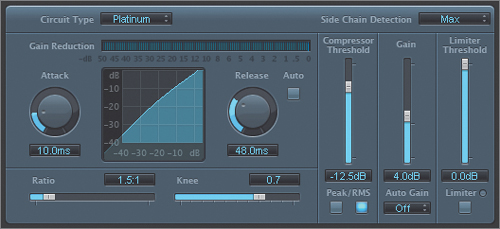
- Click the Circuit Type menu, and choose FET.
Listen to the vocal track while adjusting the Threshold and Ratio controls to govern how and when compression is applied to the incoming signal.
- Play the project.
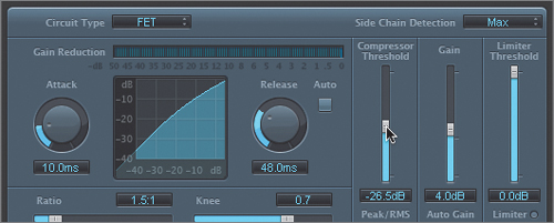
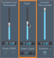
- Drag down the Compressor Threshold slider to a value of −26.5 dB.
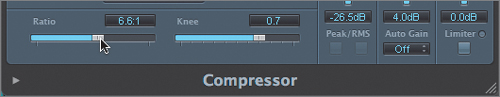
- Drag the Ratio slider to a value of 6.6:1.
The Gain Reduction meter at the top of the plug-in window gives you a visual display of how the Compressor is working with the signal. It reads around –4 dB on average levels and around –12 dB for peaks.
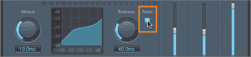
This works pretty well, but the gain reduction is happening a bit fast, creating a slightly unnatural sound for the vocal part. You can address this by increasing the attack to delay the start of the gain reduction induced by the Compressor.
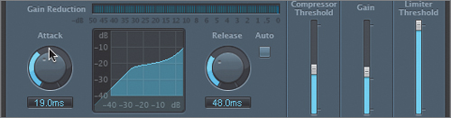
- Drag up the Attack knob to a value of 19.0 ms.
Although the speed with which a compressor responds to an incoming signal is important, no less important is the speed at which it releases that signal. Release performance and settings can greatly color sound, depending on the dynamics of the original signal and can sometimes lead to undesirable “pumping” and “breathing” effects. To create a more transparent sound, Logic’s Compressor contains an Auto mode, in addition to the manually adjusted Release knob. When Auto mode is enabled, the release time is automatically increased as volume peaks go above the threshold setting, dynamically adjusting to the audio material.
- To the right of the Release knob, click the Auto button.
Now that you’ve dialed in the basic compression settings, you should apply makeup gain to compensate for the inherent gain reduction caused by the compression process.
- Drag up the Gain slider to a level of 8.0 dB.
The volume level of the output signal is now roughly equivalent to that of the input signal, and the signal reflects the obvious dynamic smoothing that the compressor provides.
Using a Plug-in’s Extended Parameters
Many of Logic’s plug-ins (both instruments and effects) offer extended parameters that are hidden from the standard interface by default. These settings are worth exploring and are easily accessed by clicking the disclosure triangle at the lower left of the plug-in interface.
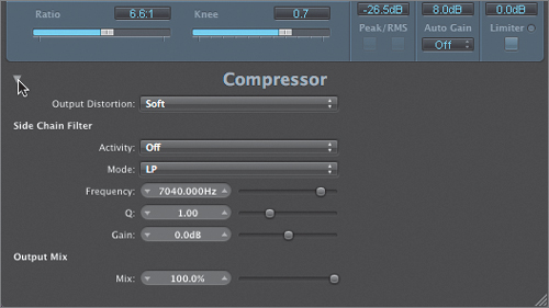
The Compressor parameters you just set sound great but could benefit from a little coloration to make the result sound more like the pleasing harmonic distortion associated with tube-based audio hardware. You can add this coloration using the Output Distortion parameter located within the Compressor’s extended parameters.
- At the lower left of the Compressor’s interface, click the disclosure triangle.
The extended parameters appear at the bottom of the plug-in window.
- From the Output Distortion menu, choose Soft. While subtle, the Soft setting introduces gentle audio clipping at the output, which is quite pleasing to the ear.
- Click the Solo button to unsolo the Vox_Lead channel and listen to the effects processing applied to the track within the context of the mix.
- Close the Compressor window.
- Stop the playback.
Using Send Effects
You can continue working with the lead vocal channel by applying some reverb. You could insert a reverb effects processor into the channel as you did with the EQ and dynamics plug-ins and then adjust the plug-in mix between the direct and processed signal to achieve satisfactory results. However, a much more efficient approach is to set up the reverb plug-in on an aux channel that can receive a signal from any channel.
With the reverb set up in such a manner, controlled amounts of signal from individual tracks can be sent to the aux via the sends on their respective channels. The audio signals are processed with the effect and mixed with the stereo output.
This carries the additional advantage of saving considerable CPU power, because a single instantiation of the effect processor is inserted, instead of the same plug-in being inserted on every channel that needs processing.
The current project already uses send effects in such a manner, instantiated on multiple aux channels within the Mixer (as mentioned earlier in “Using Arrange View”).
- If necessary, scroll to the right to see the five aux channels in the Mixer.
The first three aux channels contain reverb send effects that complement selected instruments in the mix (piano/strings, drums, guitars). So far, a send effect has not been created for a vocal reverb, which usually demands its own type of reverb processing. For this exercise, you will be creating a new reverb send effect that complements the lead vocal you’ve been working on.
Creating a new aux channel for a send effect is easy, as the aux channel is automatically created when you enable a new send selection on the track.
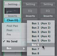
- On the Vox_Lead channel, click the top Send slot, and choose Bus > Bus 6 from the menu.
If you look at the aux channels you viewed previously, you’ll notice that a new aux channel (Aux 6) has been created, with Bus 6 set in the Input slot. You next need to insert the reverb send effect on this new aux channel, then adjust the send level on the Vox_Lead channel, moving back and forth while you adjust both the reverb settings and the send level to create a satisfactory sound. What could potentially be extremely nonergonomic (especially on a smaller monitor) is made easy by using Single view, learned earlier in the lesson.
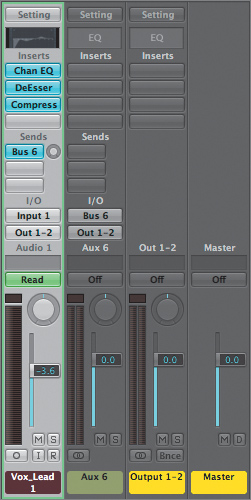
- With the Vox_Lead channel selected, click the Single button.
The Mixer displays the Vox_Lead, Aux 6, Output 1-2, and Master channel strips, representing the complete signal flow stemming from the lead vocal track.
The newly created aux channel (Aux 6) is now within easy reach of the source channel (Vox_Lead). Notice that the created aux channel is mono. This is because Logic automatically sets the format (mono, stereo, or 5.1) to match the source channel. In this situation, a stereo reverb send effect is desired, so you will need to change the format before you instantiate the plug-in.
- On the Aux 6 channel strip, click the Format button to change the track from mono (single circle) to stereo (two overlapping circles).
The channel becomes stereo, with two level meters side by side.
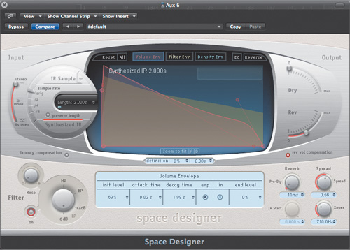
- On the Aux 6 channel strip, click the top Insert slot and choose Reverb > Space Designer > Stereo from the pop-up menu.
The Space Designer plug-in window opens.
Space Designer is a convolution reverb that uses a special audio recording of a real acoustic space (or an effect processor) to apply reverb by means of a real-time process. Think of it as a reverb sampler that imposes its sonic signature on a track.
Space Designer comes with a wealth of these acoustic space recordings, called impulse responses (IRs), on which it bases its processing. IR files, as well as any processing parameters, are stored in the effect settings.
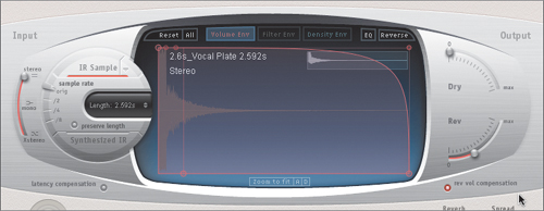
- Click the Settings menu at the top of the window (which now reads “#default”), and choose 01 Large Spaces > 03 Plate Reverbs > 02.6s Vocal Plate.
Note
If you have created custom presets of your own, Logic will list the installed factory presets in a folder named Factory. If you do not see the 01 Large Spaces folder, look in the Factory folder, and then continue along the file path specified above.
The IR takes a moment to load. After loading, you can see the visual representation of the IR, which, in this case, was sampled from an electronic reverb processor’s plate algorithm.
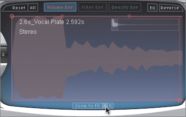
- At the bottom of the IR waveform display, click the A button.
This button allows you to zoom in on the attack area of the IR’s waveform display. The magnification helps you see how the signal will be affected by the reverb sample.
Note
If you look closely at the zoomed IR waveform, you’ll notice that the reverberation signal occurs immediately (it starts at the far left).
Space Designer offers additional processing of the IR signal via an extensive array of editing parameters. These parameters range from settings found on traditional reverb units to control settings specific to working with volume and filter envelopes.
When using reverb on vocal tracks, it is often desirable to complement the sound with predelay to separate the original signal from the reverb tail.
- At the lower right, drag up the Pre-Dly (Predelay) knob to a value of 61 ms.
Now that you’ve completed some basic adjustments to the Space Designer reverb, you can send a controlled amount of the lead vocal signal to the send effect for processing. You do this by means of adjusting the send level on the output channel strip.
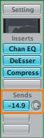
Once a send destination has been assigned, the corresponding Send knob appears next to the Send slot. By adjusting the Send knob, you can choose the amount of signal sent to the chosen destination (in this case, Aux 6).
- Click the Solo button on the Vox_Lead channel.
- Play the project.
- While listening to the lead vocal track, drag up the Send knob, setting a value of –14.9 (dB).
Note
When you solo a track assigned to an aux, Logic automatically keeps the effects return channels (aux channels) open. This automatic mute suppression allows you to hear the soloed track with the send effects applied. The same applies when you solo an effect return signal. The channels fed into the effect are muted, but their effect sends remain open, ensuring that the effect continues to receive a signal.
- Stop the playback.
- On the Vox_Lead channel, click the Solo button to unsolo the channel.
- Click the Cycle button to turn Cycle mode off.
- Close the Space Designer window.


More Info
The distributed audio processing feature in Logic Pro allows you to expand the processing capacity of your Logic Pro system by offloading calculations for software instrument and DSP effects to additional Macintosh computers that are connected by Gigabit Ethernet. This is effective when you need additional processing horsepower for CPU-intensive software synthesizers or plug-ins such as Sculpture or Space Designer. For more information on how to set up a distributed audio processing system, refer to page 99 in the Logic Pro 8 User Manual.
Panning Stereo Tracks
Logic’s Mixer channels offer true stereo functionality without requiring the user to dedicate two tracks (a left and a right channel) for playback. This provides playback of interleaved stereo files, stereo software instruments, and stereo busses through a single mixer channel, providing ease of use when working with stereo sources.
On stereo channels in the Mixer, the Balance control balances the relative levels of the left and right signals that make up the stereo signal. Adjusting the balance of a stereo track reduces one side in favor of the other.
For example, imagine a stereo drum overheads track that has the hi-hat on the left side of the spectrum and the ride cymbal on the right. If the Balance control for the track is turned to the left, then the right side of the signal diminishes, losing the ride. If the knob is turned to the right, the opposite happens, reducing the hi-hat signal in favor of the ride.
While this stereo balance function provides considerable ease of use, it also represents a limitation when it comes to the placement of a sound in the stereo field of a mix. It is often necessary to reposition the center of a recorded stereo signal within the mix while maintaining or changing the spread (stereo width). Fortunately, Logic offers a handy plug-in, the Direction Mixer, that does this on any stereo track. This plug-in allows for a more focused sound, as you are truly panning a stereo signal instead of adjusting the signal level of the left and right sides.
- Click the Arrange button.
All active channels in the project’s arrangement are displayed in the Mixer.
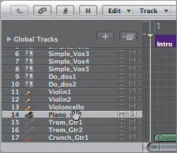
- On the Piano channel strip (track 14), click the second Insert slot, and choose Imaging > Direction Mixer > Stereo from the pop-up menu.
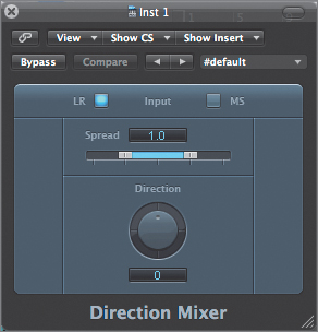
The Direction Mixer plug-in window opens.
The Direction Mixer plug-in offers the panning functionality described above by means of the Direction parameter. Graphically, the Direction knob is quite different from the Pan control used on mono tracks. Values within the range of −90 to +90 degrees represent the full stereo field, while greater and lesser values (from +90 to +180 or from −90 to −180 degrees) bring the middle of the signal back toward the center, but with the left and right sides reversed. At +180 (or −180) degrees, the signal is dead center, but with the left and right sides inverted.
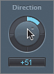
- Drag the Direction knob up to set a value of +51.
This places the center of the Piano signal slightly to the right side of the mix.
In addition to positioning the middle of the stereo signal across the stereo field, you can use the Direction Mixer plug-in to widen or tighten the spread of the stereo base by adjusting the Spread parameter. A setting of 1.0 maintains the width of the original signal, while lower settings bring the sides toward the center, decreasing the spread.
- Drag one of the Spread sliders to set a value of 0.8.
This will tighten up the stereo signal so that it doesn’t take up quite as much width in the stereo mix.
- Click the Solo button for the Piano channel.
- Press Shift-Enter (the Play from Selection command) to play the project from the beginning of the Piano part.
- While the project is playing, click the Bypass button on and off to hear the Piano track with and without the Direction Mixer.
Notice that with the Direction Mixer active, it feels as though the piano is sitting to the right of the vocalist, but the stereo image is not compromised. If you had used the main Balance control to do the same thing, you might have lost the sound of the low notes on the piano, because they are normally heard in the left side of the stereo image.
- Make sure the Direction Mixer plug-in isn’t bypassed.
- Stop the project playback.
- Close the Direction Mixer window.
- On the Piano channel, click the Solo button to unsolo the channel.
- Play the project again, this time listening to how the Piano track fits within the stereo mix.

Note
The Direction Mixer plug-in also decodes MS (middle-side) encoded stereo recordings. Once the MS mode is engaged (by clicking the MS button), you can alter the stereo signal with the Spread and Direction controls as you would with standard left-right stereo signals.
Switching the Contents of the Plug-in Window
Accessing the multitude of active plug-ins in a project can be a clumsy process requiring the opening and closing of each plug-in window. Menus in a plug-in window provide a simpler way to navigate around active plug-ins, allowing you to view any plug-in in the same window regardless of its channel or its order in the signal chain.
This navigation technique also helps when you’re copying presets from one location to another and identical processing is required. The two violin tracks are a good example of this, since they could both benefit from similar EQ and dynamics processing. In this exercise you navigate from the Violin1 channel to the Violin2 channel using the plug-in window menus, copying and pasting settings from one plug-in to another.
- In the Mixer, look at the two adjacent Violin tracks (tracks 11 and 12).
Notice that they have identical plug-ins at the same Insert slots in the channels. However, the Violin1 plug-ins have customized settings, which you will copy to Violin2.
To use this plug-in settings technique, you need to have a plug-in window open.
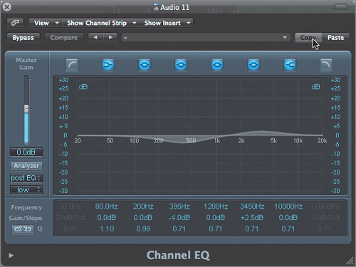
- In the Violin1 channel (track 11), double-click the Channel EQ plug-in to open the plug-in window.
The EQ curve indicates a subtle dip at around 395 Hz and a smaller boost at around 3450 Hz.
- At the upper right of the plug-in window, click the Copy button.
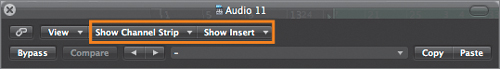
Now that you have copied the EQ plug-in settings from Violin1, you can paste them into the Channel EQ in the Violin2 channel. You will use the two “Show” pop-up menus located at the top of the plug-in window to view the Channel EQ setting for Violin2 in the same plug-in window.
The Show Channel Strip menu accesses the same numbered Insert slot on any channel that has an active plug-in.
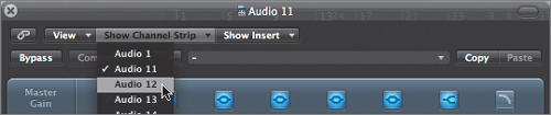
- Click the Show Channel Strip pop-up menu button, and choose Audio 12 (Violin2).
The Violin2 Channel EQ settings (default) are now displayed in the open plug-in window (identified as Audio 12).
- Click the Paste button (next to the Copy button).
The plug-in settings from Violin1 are pasted into the Channel EQ of Violin2.
- Click the Show Channel Strip menu button, and choose Audio 11 (Violin1).
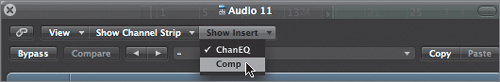
This returns you to the Violin1 Channel EQ. Let’s move on to display the Compressor plug-in, located in the second Insert slot for the channel. Each Insert slot for a single channel can be accessed by the Show Insert pop-up menu.
- Click the Show Insert menu button and choose Comp.
The Compressor interface now appears in the plug-in window.
- Click the Copy button.
- Click the Show Channel Strip menu button and choose Audio 12 (Violin2).
The Compressor inserted in the second Insert slot on the Violin2 channel is displayed in the plug-in window.
- Click the Paste button.
The plug-in setting from Violin1 is pasted onto the Compressor of Violin2.
- Close the plug-in window.
Changing Plug-in Locations
As anyone who has worked with effects processors knows, where you place an effect is as important as what effect is chosen. Inserting effects at different places in the signal chain can lead to different results depending on the processing involved.
Changing effect placement is easily done in Logic’s Mixer by dragging with the Hand tool. You can try this by changing the order of the lead vocal signal chain that you created earlier, placing the EQ after the Compressor.
- Solo the Vox_Lead channel by clicking the Solo button.
- Click the Cycle button to turn on Cycle mode.
This will bring back the cycle area you created earlier when auditioning the lead vocal.
- Choose the Hand tool.
This tool allows you to grab and move plug-ins in this window.
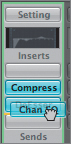
- Drag the Channel EQ in the first Insert slot on track 1 (the Vox_Lead channel), placing it in between Insert slots 3 and 4 (a yellow line will appear between Insert slots 3 and 4).
The signal chain reflects the new order, inserting the Channel EQ (including the settings) after the Compressor.
Note
When dragging plug-in locations with the Hand tool, pay special attention to the area where you release the mouse button, as this affects placement in the signal chain (top to bottom). To aid in this, a light yellow rectangle or line is displayed indicating where the plug-in will be placed. With careful placement, you can put plug-ins above or below the others (indicated by a yellow line) in the signal chain, and even swap locations (an empty target slot will be indicated by a yellow rectangle).
- Play the project and listen to the lead vocal channel with the new plug-in order.
- While it’s playing, drag the Channel EQ plug-in back to the first Insert slot.
The plug-in changes position, even when the project is playing.
- Stop the playback.
Tip
This technique also works for dragging Insert plug-ins from one channel to another. If you do this, make sure to keep format (mono, stereo, or 5.1) compatibility between the two channels in mind. You can even copy plug-ins from location to location by pressing the Option key while dragging.
Using Channel Strip Settings
Chains of multiple plug-ins (and their settings) can be saved and recalled as channel strip settings. This enables you to apply commonly used chains of effects in any project far more quickly than individually inserting each plug-in and its settings.
You used channel strip settings via the Library earlier in the book to open a software instrument that was coupled with a chain of effects (Lesson 4, “Working with Software Instruments”). This time, you’ll save the lead vocal effects chain as a channel strip setting for future use.
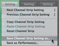
- Click the Setting button at the top of the Vox_Lead channel strip, and choose “Save Channel Strip Setting as” from the pop-up menu.
A window opens with a file selector box.
- In the Save As field, enter I Was Raised Vox, and click Save.
This will save the signal chain to a folder reserved for audio channel strip settings. The chain can be recalled on any audio channel.
Lesson Review
1. Explain the difference between the Mixer’s Arrange, All, and Single view modes.
2. In the Channel EQ, what feature enables to you to visualize both the pre- and postprocessed signals to identify and correct frequency-specific problems?
3. In the DeEsser, what features help to identify and reduce signal sibilance?
4. Which insert plug-in allows the smoothing of a signal’s dynamics and the ability to impart subtle coloration?
5. Which send effect modifies how a signal interacts with an impulse response, simulating the placement of a signal within an acoustic space?
6. Which insert plug-in aids in accurate stereo placement within a mix?
7. A plug-in’s Show Channel Strip and Show Insert menus allow what?
8. Which tool allows you to change the insert order, thereby affecting signal flow?
Answers
1. The Mixer’s Arrange view adapts to the Arrange area’s track list, and vice versa. The All view mode displays all the channels existing in a project’s Environment, and it can be used to create an alternative mixer with commonly accessed channels. The Single view displays the entire signal flow from a selected channel, including send channels and output.
2. The Channel EQ’s built-in Analyzer can help identify and correct problem bands in a signal’s frequency spectrum.
3. The DeEsser plug-in can be monitored at multiple points to identify and reduce signal sibilance. It accomplishes this by locating the problem frequency with the Detector and reducing the same frequency band (or a different band) with the Suppressor.
4. Logic’s Compressor plug-in does so with different circuit types and harmonic distortion.
5. The Space Designer convolution reverb.
6. Stereo tracks can be accurately balanced and their images adjusted by means of the Direction Mixer plug-in.
7. A plug-in’s Show Channel Strip and Show Insert menus allow navigation from plug-in to plug-in within the same window, making it easier to copy and paste settings between plug-ins.
8. The Hand tool allows you to change the insert order by dragging and dropping plug-ins within a single channel, or from channel to channel.
9. Channel strip settings can store commonly used effects chains for use in any project.