Lesson 11. MIDI Processing in the Environment
From the very beginning, the Environment has set Logic apart from other sequencers. The Environment is often thought of as a virtual studio, containing objects that represent your audio channels and MIDI devices. However, the Environment is much, much more, enabling you to process data from MIDI and software instruments in real time by creating complex signal routings and transformations to augment your music.
In this lesson, you will explore useful MIDI processors in the Environment, creating signal routings to affect MIDI input in a variety of ways.
Note
You will need to set the “Display Middle C as” preference to C3 (Yamaha) to accurately follow the directions in this exercise (and others throughout the book). This command can be found in the Preferences > Display > General tab.
Navigating Within the Environment
The Environment is tucked neatly away within its own window, which can be accessed like any other, via the main Window menu. Like other windows, the Environment window can be part of a screenset, which helps to keep things organized.
- Choose File > Open.
- In the file selector box, go to Music > Logic 8_BTB_Files > Lessons and open 11_MIDI Processing.logic.
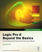
The project opens, displaying Screenset 1, which consists of an Arrange window (with the Library displayed) placed above an Environment window.
The Environment is divided into layers, displaying objects of like type or function. You are currently looking at the All Objects layer, which provides an easy way to look at all objects currently within the project’s Environment. Here, you can see the three software instruments (Marimba, 8bit Kit, and Analog Lead) assigned to the Arrange track list, as well as other objects being used “behind the scenes” for MIDI input.
- In the Arrange track list, click the Marimba, 8bit Kit, and Analog Lead tracks (tracks 3–5) one at a time, playing your MIDI keyboard to familiarize yourself with the sound of the software instruments.
When you select a track in the track list, MIDI input from your controller is routed to the track’s assigned channel. Notice that when you select tracks in the track list, the corresponding Environment object is also selected.
- Click the Marimba track (track 3) in the track list, selecting it for MIDI input.
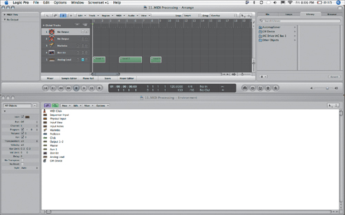
Navigating layers is done by clicking the arrow button next to the Layer menu, located in the upper-left corner of the Environment window.
- Choose Click & Ports from the Layer menu.
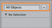
The layer switches, displaying the contents of the Click & Ports layer.
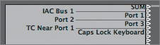
The Click & Ports layer contains objects specific to the routing of MIDI signals from their initial input till they reach Logic’s sequencer. The Physical Input object at the far left represents your MIDI interface or MIDI controller (with direct MIDI-to-USB or FireWire connection). All available ports from your MIDI input devices will be listed in the Physical Input object (including the Caps Lock Keyboard and virtual ones like the IAC Bus). Their corresponding cable outputs are depicted by the small triangles running along the right side.
Note
The SUM output at the top carries a combination of all MIDI input ports displayed in the Physical Input object that do not have their own output cables. When a cable is connected from one of the remaining MIDI ports, its signal will not be passed through the SUM output.
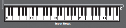
MIDI signals are passed from object to object in the Environment by cabling them together. The left side of an object represents the input, while the right side represents the output. As you can see in this layer, the Physical Input is cabled to a keyboard object, labeled Input Notes.
- Play a few notes on your MIDI controller, observing the keyboard object.
Note
If you don’t have a MIDI controller handy, the Caps Lock Keyboard will work equally well for the exercises in this lesson.
As you play the keys on your MIDI controller, the software instrument you selected in the track list (Marimba) is triggered, while the corresponding pitches are displayed in the keyboard object.
- Click some of the keys on the keyboard object.
The Marimba is triggered each time you click the keyboard object.
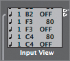
You have probably noticed that when you play a note on your MIDI controller or click the keyboard object, MIDI events are displayed in the Input View object cabled to the output of the keyboard object. This is a monitor object, which displays all MIDI data passing through it in list form.
The signal chain finally ends with a Sequencer Input object. This represents the connection to Logic’s sequencer and routes to the selected track in the Arrange track list.
By having the Physical Input cabled to the Sequencer Input (passing through the keyboard and monitor objects), MIDI signal flows from the MIDI interface or controller providing input, ultimately arriving at the selected Arrange track via the Sequencer Input object.

Creating Environment Objects
Now that you’ve had a chance to observe signal flow within the Click & Ports layer, you can try creating Environment objects to process incoming MIDI signals. Although new objects can be inserted in any layer, in this case it makes sense to create an Environment layer to house the new objects you will be exploring in this exercise.
- Choose Create Layer from the Layer menu.
An empty layer is created.
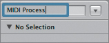
- Select “(unnamed)” in the Layer menu text field, and enter MIDI Process. Press Return.
You now have a new layer to house your MIDI processing experiments, ready for new objects to be added.
Using Monitor Objects
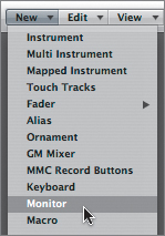
As you noticed previously in the Click & Ports layer, monitor objects are used to display MIDI signals passing through them. New ones can be created by choosing them from the Environment window’s New menu.
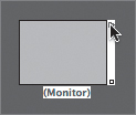
- In the Environment’s local menu bar, choose New > Monitor.
A new monitor object appears.
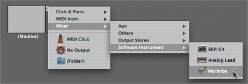
By itself, a monitor object does nothing. In this exercise, you will be using it to both monitor MIDI signals passing through it and to connect to the Marimba software instrument channel selected in the Arrange area. In order to pass the signal, you need to cable the output of the monitor object to the Marimba software instrument channel, which is housed in a different layer (the Mixer layer). Even though these objects exist in different layers, you can still cable them together by first holding down the Option key, and then clicking the cable output of the monitor object.
- While holding down the Option key, click the cable output (the small triangle in the upper-right corner) of the monitor object.
A menu appears, allowing you to set the destination for the cable.
- Choose Mixer > Software Instrument > Marimba.
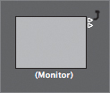
A cable appears, connecting the objects between the layers of the Environment.
Note
Once an output from an object is used (cabled to another object), another output triangle automatically appears.
In order to keep things straight, it’s a good idea to label objects as you create them.
- Using the Text tool, click the monitor object to rename it.
- Enter To Marimba. Press Return.
- Switch back to the Pointer tool and drag the monitor object to the right side of the Environment window, to make room for other objects.
Using Arpeggiator Objects
Arpeggiator objects receive harmonic input (simultaneous notes), outputting each note individually in a variety of selectable patterns, speeds, and lengths. Logic’s arpeggiator objects are extremely flexible and can be configured to create complex rhythmic patterns out of static chords.
- From the Environment’s local menu bar, choose New > Arpeggiator.
A new arpeggiator object appears.
In this exercise you will not only be creating new Environment objects, but also be cabling them in a variety of ways to process MIDI data. To aid in visualizing the signal routing from one object to the next, you can color the objects and their respective cables.
- Choose View > Colored Cables.
- Chose View > Colors.
The color palette appears, allowing you to assign colors to selected objects.
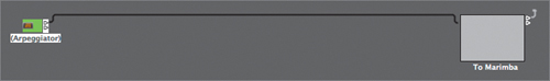
- With the arpeggiator object still selected, click a shade of green in the color palette.
The arpeggiator object becomes green.
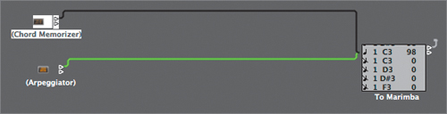
- Click and hold down the cable output of the arpeggiator object, dragging the new cable to the monitor object.
You now have a connection between the arpeggiator and the Marimba software instrument channel (passing through the monitor).
In order for the arpeggiator to receive input from your MIDI keyboard, you need to bring it up on a track in the Arrange area. Rather than go back to the Arrange area to do this, you can use the MIDI Thru tool in the Environment. Any object you click in the Environment using this tool will be configured for the currently selected Arrange track.
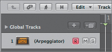
- In the Arrange area, select the top No Output track (track 1) in the track list.
- Using the MIDI Thru tool, click the arpeggiator object.
The selected Arrange track (track 1) changes to the arpeggiator object.
You can test to see if the arpeggiator is receiving input by playing your MIDI controller.
- Play a few notes on your MIDI controller, observing the monitor within the Environment window.
You should hear the Marimba software instrument as well as see MIDI data displayed in the monitor object.
The arpeggiator object works with tempo-related material, so in order to have it process the incoming MIDI, the project has to be playing.
- Play the project.
- While the project is playing, hold down a chord (any combination of notes) on your MIDI controller.
You should now hear the chord arpeggiated as well as see the resultant MIDI data displayed in the monitor object.
- Try adding or subtracting notes to your held chord, observing how they change the arpeggio.
Note
It is important for the project to remain playing in order for many of the Environment objects to process incoming MIDI notes. Throughout the lesson, if you reach the end of the project, return to the beginning and start playback again.
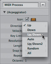
In the Object Parameter box, you will find many useful settings for the arpeggiator object. Here, you can select from various patterns as well as adjust the velocity, speed, length, and octave of the arpeggiated notes.
- In the Object Parameter box, click the Direction pop-up menu and choose Up/Down.
The pattern direction changes, arpeggiating up and then down the notes of the chord.
- In the Object Parameter box, click the Direction menu again, this time choosing Random.
The pattern changes, randomly arpeggiating selected notes from the chord.
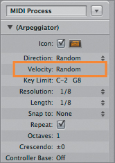
The Velocity parameter allows you to adjust the velocities of the arpeggiated notes of the original chord. You can set a positive or negative offset, or even randomize the velocities.
- In the Object Parameter box, drag the Velocity parameter (it currently displays “Original”) down to choose Random.
The velocities of the arpeggiated notes are randomized.
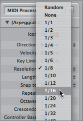
The speed of the arpeggio is governed by the Resolution parameter, which is defined by note divisions (half note, quarter note, and so on).
- Click the Resolution menu and choose 1/16.
The arpeggiated notes change to a sixteenth-note resolution, playing twice as fast as before.
To enable synchronization with other MIDI data, the arpeggiator can be set to wait for a specific note division before starting. This is done with the “Snap to” parameter.
- Click the “Snap to” menu and choose 1/8.
This quantizes the start of arpeggiated playback to the following eighth note, keeping it in sync with the project’s time grid (bars/beats).
- Stop playback.
Using Chord Memorizer Objects
Chord memorizer objects map a single note to a set of up to 12 user-selected notes. This allows you to trigger complex chords by pressing a single key on your MIDI controller.
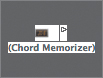
- Choose New > Chord Memorizer.
A chord memorizer object appears in the Environment window.
- With the chord memorizer object selected, click a shade of dark blue in the color palette.
The chord memorizer object becomes blue.
- Cable the output of the chord memorizer object to the monitor object.
- Double-click the chord memorizer object.
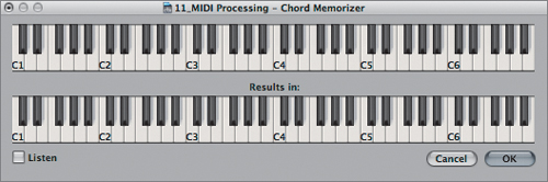
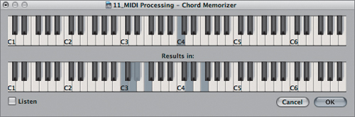
The Chord Memorizer window opens.
The Chord Memorizer window contains two keyboards. The top keyboard corresponds to the incoming note, and the lower keyboard corresponds to the notes or chords assigned to the incoming note.
- Click the C4 note on the top keyboard.
C4 is automatically selected in the lower keyboard.
- In the lower keyboard, click C4 to deselect it.
- In the lower keyboard, click C3, D3, E
 3, F3, D4, and F4 to select them.
- Click OK.
In order for the chord memorizer to process the input from your MIDI controller, you need to bring it up in the Arrange track list. Instead of doing this by using the MIDI Thru tool as you did before, you can quickly assign objects in the Environment to the selected track using the Library.
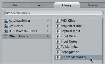
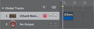
- In the Library, choose Other Objects > (Chord Memorizer).
The selected Arrange track (track 1) changes from the arpeggiator object to the chord memorizer object.
Because the chord memorizer is not time based, you don’t need to have the project playing in order for it to process MIDI input.
- Press C4 on your MIDI controller.
A full chord is sounded, outputting the notes you specified within the lower keyboard of the Chord Memorizer window (C3, D3, E
3, F3, D4, and F4).
Using Delay Line Objects
Delay line objects repeat the MIDI events passing through them, achieving a result similar to that of a delay processor creating echoes from audio signals. The most important difference between the two is that the delay line object creates these echoes with additional generated MIDI notes that mirror the incoming MIDI event, instead of sampling and playing back bits of audio.
- Choose New > Delay Line.
A delay line object appears in the Environment window.
- With the delay line object selected, click a shade of yellow in the color palette.
The delay line object becomes yellow.
- Cable the output of the delay line object to the monitor object.
Like the other objects, the delay line needs to be placed in the Arrange track list so it can process the input from your MIDI controller.
- In the Library, choose Other Objects > (Delay Line).
The selected Arrange track (track 1) changes from the chord memorizer object to the delay line object.
As with the arpeggiator object, the project needs to be playing for you to hear the results of the delay line object’s processing.
- Play the project.
- While the project is playing, play any note on your MIDI controller, listening to the signal through the delay line object.
The incoming note is echoed by a single repeat.
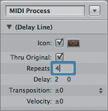
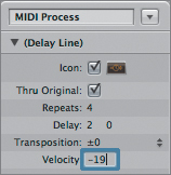
You can adjust the repeat amount, timing, velocity, and transposition within the Object Parameter box.
- In the Object Parameter box, double-click the number next to the Repeats parameter, and enter 4. Press Return.
- While the project is playing, play any note on your MIDI controller, listening to the signal through the delay line object.
The incoming note is repeated four times. This doesn’t sound much like natural echoes, where the repetitions trail off in volume. You can simulate this effect by adjusting the Velocity parameter to a negative value. By doing this, each successive repeat will lower in velocity by the selected amount.
- Double-click the number to the right of the Velocity parameter, and enter –19. Press Return.
- While the project is playing, play any note on your MIDI controller, listening to the signal through the delay line object.
The incoming note is echoed four times, each echo quieter than the previous one.
The speed of the repeats can be set by the Delay parameter. The left value represents divisions, while the right value represents ticks. This allows you to make musical repeats that sync with the tempo of the project.
- In the Delay parameter fields, double-click either number and enter 240. Press Return.
- While the project is playing, play any note on your MIDI controller, listening to the signal through the delay line object.
The delay time between the repeats is cut in half.
So far you have emulated the results you’d get from a typical audio delay processor. The delay line also allows you to do something unusual: transpose the pitch of each repetition.
- Double-click the Transpose parameter and enter –7. Press Return.
- While the project is playing, play any note on your MIDI controller, listening to the signal through the delay line object.
Each successive repetition drops seven semitones (a perfect fifth).
- Stop playback.

Creating Signal Chains
So far, you’ve only applied single processors (arpeggiator, chord memorizer, and delay line) to incoming MIDI signals. The Environment starts to show its potential, however, when you cable processors to each other for complex serial and parallel processing.
In this exercise, you will not only learn how to chain processors together in a series but also how to split signals for parallel processing.
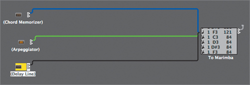
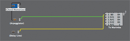
- Click and hold down the topmost cable output from the chord memorizer object and drag the cable to the arpeggiator object.
- In the Library, choose Other Objects > (Chord Memorizer).
The selected Arrange track changes to the chord memorizer object.
The incoming MIDI signal now passes from the chord memorizer object to the arpeggiator object, finally ending up at the Marimba software instrument channel (passing through the monitor object). With these two in series, you can trigger complex arpeggiated chords by pressing a single note on your MIDI controller.
- Start playback.
- While the project is playing, play C4 on your MIDI controller (which you earlier set to play back a chord).
The chord generated by the chord memorizer object is arpeggiated.
Let’s add to this creation by inserting the delay line object into the signal path.
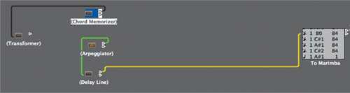
- Click and hold down the cable output from the arpeggiator object and drag the cable to the delay line object.
With this arrangement, each note from the arpeggiated chord generated by the chord memorizer and arpeggiator objects will repeat four times, dropping seven semitones each time. All of this is triggered by a single note from a MIDI controller.
- While the project is playing, play C4 on your MIDI controller.
A whole slew of notes is created, with various pitches and rhythmic durations.
- Stop playback.
Using Transformer Objects
Now that you’ve investigated chaining MIDI processors in a series, let’s create a parallel processing arrangement in which specified notes will be sent down two different signal paths. You can do this by using the transformer object.
The transformer object is an extremely powerful processor whose main function is to change one type of MIDI data to another. However, that would be barely scratching the surface of its capabilities. It also works equally well as a MIDI filter, track automation splitter, SysEx mapper, condition splitter, and much more. For this exercise you will be using the Transformer as a condition splitter, sending data down one of two cable outputs depending on criteria you set.
- Choose New > Transformer.
A transformer object appears within the Environment window.
- With the transformer object selected, click a shade of red in the color palette.
The transformer object becomes red.
- Double-click the transformer object.
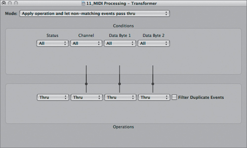
The Transformer window opens.
This window is almost identical to the Transform window explored in Lesson 7, “Advanced MIDI Editing,” in the section “Using Transform Functions.” Like the Transform window you used within the MIDI editors to select and edit MIDI data, the Transformer window has places to specify criteria for selection and transformation. Like the Transform window, the Transformer window also has many modes available.
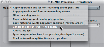
- Click the Mode menu at the top of the window and choose Condition splitter (true -> top cable).
The condition splitter mode sends MIDI data that meets the conditions specified within the top area (Conditions) out the topmost cable output and sends all other MIDI data that does not fit the criteria out the other. In this exercise, you will be using the condition splitter to divide specific notes generated by the chord memorizer object out one of the two cable outlets for separate processing chains.
- From the Status menu, choose =.
Another pop-up menu displaying Note appears below the Status menu.
- From the Pitch menu, choose <=.
A value field appears just below the pop-up menu.
- Double-click in the value field and enter C4. Press Return.
With this setup, incoming note values equal to and below C4 will be sent out of the top cable output, while all others will be sent out of the bottom output.
- Close the Transformer window.
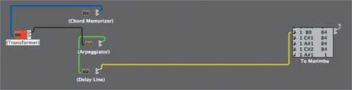
- Click and hold down the topmost cable output from the chord memorizer object and drag the cable to the transformer object.
The chord memorizer object will provide the input to the transformer object.
- Click and hold down the cable output from the transformer object and drag the cable to the arpeggiator object.
You’ve now set up one of your signal chains distributed by the transformer object. Now all you need to complete the arrangement is to set up another signal path to process data that does not meet the conditions specified in the transformer object. Begin by creating another monitor object cabled to a different software instrument channel.
- Choose New > Monitor.
A new monitor object appears.
- Drag the new monitor object down and to the right, moving it out of the way of the first signal chain.
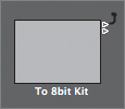
- Using the Text tool, click the new monitor object and enter To 8bit Kit.
- Option-click the cable output on the monitor object and choose Mixer > Software Instrument > 8bit Kit.
A cable appears, connecting the objects between the layers of the Environment.
- Choose New > Arpeggiator.
A new arpeggiator object appears.
- With the new arpeggiator object selected, click a shade of yellow in the color palette.
The arpeggiator object becomes yellow.
- Drag the new arpeggiator object down, moving it out of the way of the first signal chain.
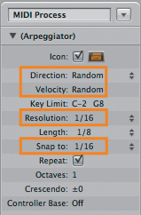
- In the Object Parameter box, choose Random for the Direction and Velocity parameters, and 1/16 for the Resolution and “Snap to” parameters.
- Cable the output of the new arpeggiator object to the monitor object labeled To 8bit Kit.
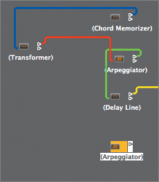
- Cable the bottommost cable of the transformer object to the new arpeggiator object.
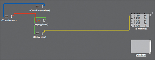
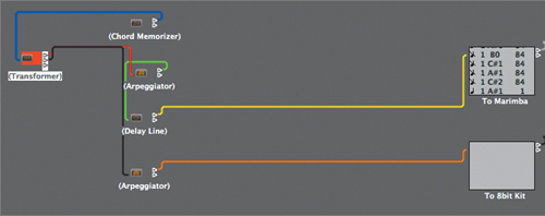
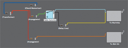
You’ve now set up two complete signal chains with separate processing. The source events are generated by the chord memorizer object, with the transformer object splitting the data by note range (those equal to or below C4, and those above C4). Now all that’s left is to try it out.
- Start playback.
- While the project is playing, hold down C4 on your MIDI controller.
What results are pulsating, surging polyrhythms that never repeat twice, activated by a single key on your MIDI controller.
- Stop playback after you’ve listened to your creation.


Using Cable Switcher Objects
Like a transformer object, a cable switcher object is used to help direct signal flow. Basically, the cable switcher object is a switch that can be triggered manually to direct the signal flow out of its outputs. The switch can take on different forms, such as a fader button or pop-up menu, allowing you to interact with it in different ways.
In this exercise, you will insert a cable switcher into the signal path, enabling you to switch between two routes at any given time.
- Choose New > Fader > Specials > Cable Switcher.
A cable switcher object appears.
- With the cable switcher object selected, click a shade of light blue in the color palette.
The cable switcher object becomes blue.
- Close the Color window (you won’t need it for the rest of the lesson).
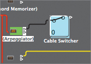
- Drag the cable switcher to the right of the topmost arpeggiator object (the green one connected to the Marimba software instrument channel).
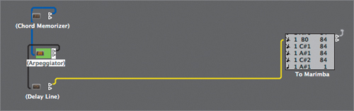
- Click and hold down the topmost cable output of the green arpeggiator and drag the cable to the cable switcher.
- Click and hold down the cable output of the cable switcher object, and drag the cable to the monitor object labeled To Marimba.
This will form one signal path, directly feeding the Marimba software instrument channel.
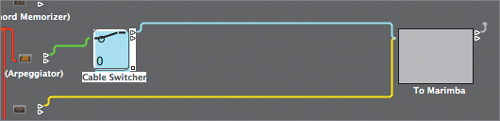
- Click and hold down the bottommost cable output of the cable switcher object, and drag the cable to the delay line object.
To make signal flow easier to view, it helps to move the delay line object to the right of the cable switcher object.
- Drag the delay line object to the right, placing it below and to the right of the cable switcher object.
This will form the other signal path, passing through the delay line object and eventually reaching the Marimba software instrument channel.
- Try clicking a few times on the cable switcher object itself.
The cable switcher changes configuration, routing the input to a different cable output each time you click.
Notice that there are three output destinations to select, and only two are cabled to signal paths. Like any other Environment object, the cable switcher adds an additional cable output (up to 128) when a new output cable is connected.
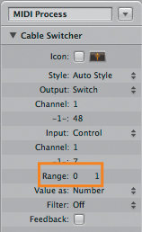
In order to have the cable switcher route only to the used outputs, you need to alter its range in the Object Parameter box. The Range parameter is expressed by two numbers, forming the bottom (left number) and top (right number) of a specified range.
- In the Object Parameter box, drag the rightmost Range parameter (127) down until it reaches a value of 1.
This sets the Range from 0 to 1 (two outputs), and allows the cable switcher object to toggle between the two signal paths connected to its cable outputs.
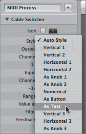
As mentioned earlier, the cable switcher object’s interface can be changed to reflect different types of switches. This is done by choosing an option from the Style menu in the Object Parameter box.
- Click the Style menu and choose As Text.
The cable switcher object changes, displaying text. By default, the displayed text corresponds to the numbered cable output (0 or 1), and the number can be toggled by clicking the cable switcher itself. This is not a particularly elegant solution for labeling and accessing the signal paths cabled to the cable switcher’s outputs. However, you can enter your own text instead of the default Range numbers, allowing clearer labels of the signal paths.
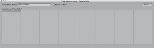
- Double-click the cable switcher object.
The Cable Switcher window opens.
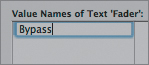
- Double-click the topmost field of the Value Names of Text ‘Fader’ column and enter Bypass. Press Return.
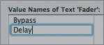
- Within the second field, enter Delay. Press Return.
Note
There are 128 fields in the Cable Switcher window that can hold text. When using cable switcher objects with large ranges displayed as text, select the Behave as Menu checkbox at the top of the Cable Switcher window. This lets you access the entire range via a pop-up menu, instead of clicking the cable switcher itself.
- Close the Cable Switcher window.
The cable switcher object now displays the text you entered in the Cable Switcher window.
Note
You can resize any Environment object by dragging its lower-right corner, similar to how you adjust window size. This enables the cable switcher object to display longer text.
Now it’s time to try out the cable switcher object while the project is playing. In order to have your hands free to interact with the cable switcher object, you can create a MIDI region with a C4 note held to trigger the rhythmic patterns played on the Marimba and 8bit Kit software instrument channels.
- In the Arrange area, use the Pencil tool to create a one-measure MIDI region in the Chord Memorizer track (track 1), starting at 1 1 1 1.
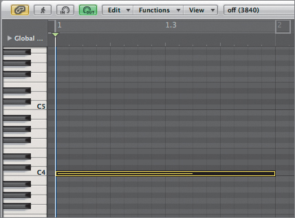
- With the region you just created still selected, choose Window > Piano Roll.
The Piano Roll Editor opens in a separate window.
- In the Piano Roll Editor, use the Pencil tool to create a C4 note with a velocity of 80 that lasts the entire length of measure 1.
- Close the Piano Roll Editor.
- In the Arrange window’s Region Parameter box, click the checkbox next to Loop to select it.
The region is now looped and will continually supply a C4 to drive the rhythmic patterns played by the Marimba and 8bit Kit software instruments.
- Play the project.
- While the project is playing, click the cable switcher object, switching back and forth between the signal paths (with the delay line object and without).
- Stop playback.


Using Touch Tracks Objects
Touch tracks objects allow you to trigger MIDI regions or folders by playing single notes. This works especially well in a live performance setting, because you can trigger anything from short passages or phrases to entire songs with a single key from your MIDI controller.
When triggered within a touch tracks object, these MIDI regions or folders play back through the instruments assigned to their tracks, sharing the same track-channel relationship they have in the Arrange window. This means that you can have a single touch tracks object that plays back MIDI regions from different tracks, all through their respective channels (and sound sources).
In this exercise you will be using a touch tracks object to play back the MIDI regions present in the Arrange tracks. Notice that these regions are muted (the track Mute button is active) and have not been sounding when the project is played. However, muted regions will sound when triggered via a touch tracks object. This allows you to create MIDI recordings via normal methods in the Arrange window for import to a touch tracks object, then muting the regions so they don’t sound when the project is played.
- Choose New > Touch Tracks.
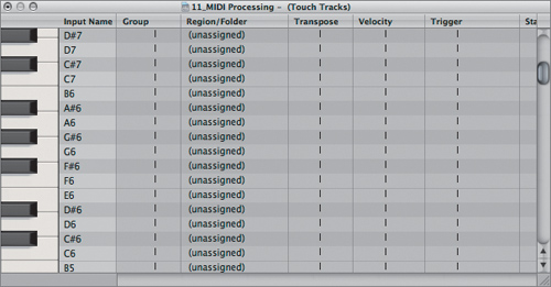
A touch tracks object appears in the Environment, and its corresponding Touch Tracks window opens.
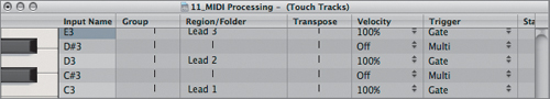
In this window you can assign different MIDI regions (or folders) to each key, represented on the far left of the window. Assignment is done by dragging from the Arrange area to the target row in the Region/Folder column.
- Scroll down in the Touch Tracks window until you can see a range of roughly C2 to E3.
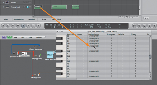
- Drag the first region (Lead 1) on the Analog Lead track to the Touch Tracks window and drop it on the C3 row in the Region/Folder column (the cursor will change to the Pencil tool).
Note
You might need to reposition the Touch Tracks window in order to see both it and the Arrange tracks.
The name of the region now appears in the Regions/Folder column for C3.
- Drag the second region (Lead 2) on the Analog Lead track to the Touch Tracks window and drop it on the D3 row in the Region/Folder column.
The name of the region now appears in the Regions/Folder column for D3.
- Drag the third region (Lead 3) on the Analog Lead track to the Touch Tracks window and drop it on the E3 row in the Region/Folder column.
The name of the region now appears in the Regions/Folder column for E3.
Now that you’ve specified the regions to be played back and assigned them to MIDI notes, you need to place the touch tracks object on a track in order for it to receive MIDI input.
- In the Arrange track list, select the No Output track (track 2).
- In the Library, choose Other Objects > (Touch Tracks).
Note
In order to work, the touch tracks object must receive MIDI note input. However, it will not pass MIDI events through to its output, so generally it should not be inserted in the signal chain unless it appears at the end.
In order for the touch tracks object to play back the MIDI regions, the project has to be playing.
- Play the project.
- With the project playing, try playing the C3, D3, and E3 keys one at a time on your MIDI controller, holding them down for various lengths of time.
The triggered Lead 1, Lead 2, and Lead 3 regions play whenever you press a key, for as long as the key is held or until the regions end. This playback behavior is referred to as the gate trigger mode, and is the default mode for any region imported into the Touch Tracks window.
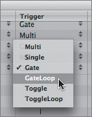
You can change the triggering behavior for any region by changing the setting within the Trigger column in the Touch Tracks window.
- In the Touch Tracks window, click the Gate setting in the Trigger column for the C3 note (Lead 1), and choose GateLoop.
This setting acts similarly to Gate, except that it will continue to repeat the region for as long as the key is depressed.
- Change the Trigger setting for D3 (Lead 2) and E3 (Lead 3) to GateLoop.
- With the project playing, try playing the C3, D3, and E3 key one at a time on your MIDI controller, holding them down for various lengths of time.
The region playback is looped for as long as you hold down a key.
Using Apple Loops with Touch Tracks
Any type of MIDI region is fair game for use with touch tracks. This means that you can also use imported MIDI regions like Standard MIDI files and software instrument Apple Loops (green Apple Loops). In particular, software instrument Apple Loops consist of MIDI regions paired with a sound source (software instrument and effects settings are instantiated when you drag them to your project) and can be easily dropped into the Touch Tracks window for triggering. In effect, you can use touch tracks to trigger these loops similar to the way a sampler would trigger audio files, mapping individual loops to the keyboard.
In this exercise, you will import a few software instrument Apple Loops for use in the touch tracks object that you created earlier.
- Click the Loops tab in the Media area.
- In the search field, enter disco pickbass.
The Loop Browser displays a variety of software instrument Apple Loops with the words disco pickbass in their names.
- Click the Disco Pickbass 03 loop in the Loop Browser, playing it in order to familiarize yourself with the material.
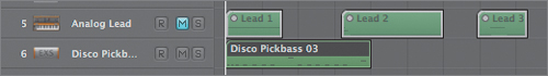
- Drag the Disco Pickbass 03 loop to the blank area below the existing tracks.
A new track is created with the Disco Pickbass channel strip, and the Apple Loops region (Disco Pickbass 03) appears on the track.
- Click the Disco Pickbass 06 loop in the Loop Browser (you will need to scroll down the list), playing it in order to familiarize yourself with the material.
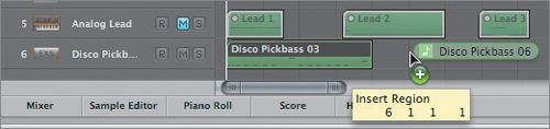
- Drag the Disco Pickbass 06 loop to 6 1 1 1 on the Disco Pickbass track (track 6).
- The Apple Loops region (Disco Pickbass 06) appears on the track.
- Click the track Mute button for the Disco Pickbass track, muting the regions you just imported.
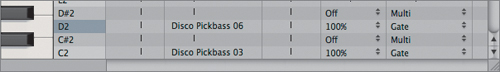
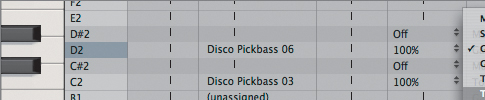
- Drag the Disco Pickbass 03 region to the Touch Tracks window and drop it in the Regions/Folder column for C2.
- Drag the Disco Pickbass 06 region to the Touch Tracks window and drop it in the Regions/Folder column for D2.
Previously, you set up the Lead regions to be triggered when a key was depressed and to repeat until the key was released (GateLoop). This time, you are going to set up the triggering a little bit differently, allowing the region to continue looping even after the key is released, not stopping until a subsequent key is depressed. You can accomplish this with another Trigger setting, ToggleLoop.
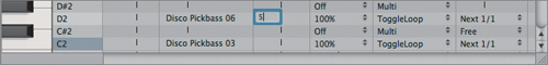
- In the Touch Tracks window, click the Gate setting in the Trigger column for both the C2 and D2 notes (Disco Pickbass 03 and Disco Pickbass 06) and choose ToggleLoop.
The way things are set up so far, the regions could be triggered at any part of the measure, on or off the beat. While this is fine for the rubato Lead regions, the Disco Pickbass regions could play out of sync with the rhythmic patterns being generated by the arpeggiator and delay line objects.
For just this sort of situation, the Touch Tracks window provides a way to quantize the playback start by changing settings in the Start column.
- Expand the Touch Tracks window in order to view the Start column.
- Click the vertical black line in the Start column for the C2 note (Disco Pickbass 03), and choose Next 1/1.
The 1/1 setting quantizes playback to the next whole note, starting the region playback at the beginning of the bar.
- Click the vertical black line in the Start column for the D2 note (Disco Pickbass 06) and choose 1/1.
In addition to the settings discussed earlier in the lesson, the Touch Tracks window also allows you to transpose individual regions by entering an offset in the Transpose column.
- Double-click to the left of the vertical black line in the Transpose column for the D2 note (Disco Pickbass 06), and enter 5. Press Return.
This setting will transpose the Disco Pickbass 06 region up five semitones (a perfect fourth) upon playback.
Note
This is different from the typical transposition behavior of samplers, as the length and speed of the region will not be altered, keeping it in perfect time with the project.
Now you are ready to test your creation.
- Play the project.
- While the project is playing, play the C2 keys and D2 keys one at a time on your MIDI controller.
The Disco Pickbass regions play back in time with the project and are toggled on or off when subsequent keys are depressed. In addition, the Disco Pickbass 06 region plays back a perfect quarter higher, changing the harmonic underpinning of the composition.
- While the project is still playing, try triggering one of the Disco Pickbass regions (C2 and D2), letting it loop while triggering the Lead regions (C3, D3, and E3) on top.
- Stop the project.
- Choose File > Save As.
- Name the project 11_MIDI Processing_Finished and save to Music > Logic 8_BTB_Files > Lessons > Completed.
Lesson Review
1. How are layers used within the Environment?
2. What does the Physical Input object represent?
3. What does the keyboard object do?
4. What does the monitor object do?
5. What does the Sequencer Input object represent?
6. How do you cable an object from one layer to another?
7. What does an arpeggiator object do?
8. What does a chord memorizer object do?
9. What does a delay line object do?
10. What does a transformer object do?
Answers
1. Layers are used to organize objects of like type or function within the Environment.
2. The Physical Input object represents the ports of your MIDI interface or MIDI controller (with direct MIDI-to-USB connection).
3. The keyboard object displays incoming MIDI notes as well as generating new ones from its output.
4. Monitor objects display MIDI events passing from their input to their output in a list form.
5. The Sequencer Input object represents the connection to Logic’s sequencer.
6. Cabling across layers is performed by Option-clicking the output of the object and selecting the input object from the menu.
7. An arpeggiator object arpeggiates harmonic input (chords), outputting each note individually in a selectable pattern.
8. Chord memorizer objects map a single note to a set of up to 12 user-selected notes.
9. Delay line objects repeat MIDI events passing through them, achieving a result similar to that of a delay processor creating echoes from audio signals.
10. Transformer objects primarily change one type of MIDI data to another. They can also act as a MIDI filter, track automation splitter, SysEx mapper, and condition splitter.
11. Cable switcher objects are used to manually direct the signal flow out of multiple outputs.
12. Touch tracks objects allow you to trigger MIDI regions or folders by playing single notes.