
CHAPTER 4
Properties of Steam and Steam Generators
Learning Objectives
4.1 INTRODUCTION
Steam is a gaseous form of water, which has a large number of industrial applications. Steam is widely used for power generation purpose. Also, it has applications in chemical, leather, and other industries. Most of the nuclear and thermal power plants use steam to run the turbines and finally to generate electrical power. Therefore, all the engineers require basic idea about steam properties, the steam generation process, and apparatus for steam generation.
4.2 FORMATION OF STEAM AT CONSTANT PRESSURE
Steam is the gaseous form of water and ice. When heat applied to the ice at 0°C is equal to the latent heat of fusion plus sensible heat from 0°C to 100°C plus latent heat of vaporization, ice is transformed into steam. Three variables are very important that are pressure, temperature, and volume. At constant pressure variation in temperature and volume can be explained by Figure 4.1.
Suppose unit mass of ice below freezing point is kept in a cylinder and a constant pressure is applied by a piston with a constant load. Now the heat is applied. From point 1 and 2 ice gets warm up and temperature increases with volume. The temperature at point 2 is 273 K.

FIGURE 4.1
T-V Diagram for Various Phases of Water
From point 2 to 3, the temperature remains constant due to the heat added is absorbed in phase transition as latent heat of fusion (hfg). At point 3 ice transforms completely into the water. On further heating from point 3 to 4, volume decreases up to 4°C (277 K), since water has a high density at 4°C. This is sensible heating. From point 4 to 5, temperature and volume, both increase on sensible heating. Again from point 5 to 6, the temperature remains constant, but the volume increases due to phase transition from water to vapor. Heat absorbed in this phase is latent heat of vaporization. At point 6, water transforms completely into vapor. Beyond point 6, the vapor is superheated and temperature rises continuously. This temperature rise is known as the degree of superheat. If several graphs are plotted between temperature and volume at different pressures, we get a curve which is shown in Figure 4.2.
At a pressure of 0.006112 bar, the melting point and boiling point become equal and change of phase ice-water-vapor is shown by a single straight line ABC as shown in Figure 4.2, is known as a triple point line. At this line, all the three phases are in equilibrium (Ptriple = 0.006112 bar, Ttriple = 273.16°C. At a very high pressure, latent heat of vaporization becomes zero, which is known as critical point (Pc = 221.2 bar, Tc = 647.3°C, Vc = 0.00317 m3/kg).
Similarly, P-V diagram, T-S diagram, h-S diagram, P-S diagram are shown in Figure 4.3:
Enthalpy Change in Generation of Steam from 0°C
At 0°C

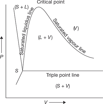
FIGURE 4.3 (a)
P-V Diagram
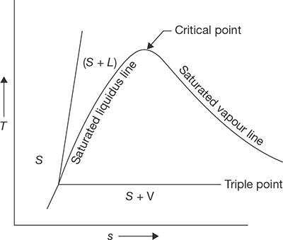
FIGURE 4.3 (b)
T-S Diagram
0°C to Saturation Temperature
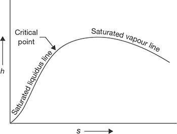
FIGURE 4.3 (c)
h-S Diagram

FIGURE 4.3 (d)
P-S Diagram
For Complete Transformation of Steam
Wet Steam
Wet steam contains partly water as suspended in it and partly steam.
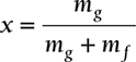
Dryness Fraction
Dryness fraction is defined as the mass of dry steam per kg of wet steam. It is represented by x.
Enthalpy
Specific Volume
Internal Energy
Entropy of Water

Entropy of Steam
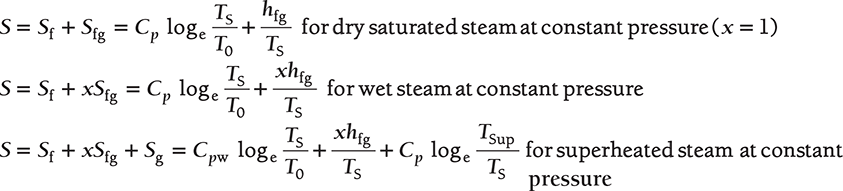
where Cpw ≈ 1, specific heat of water.
Since the value of Cp varies, the values of entropy from these equations are not accurate and this can be taken from the steam table.
EXAMPLE 4.1
- Find the temperature, enthalpy, entropy, internal energy, the specific volume of 1 kg of dry saturated steam at 10 bar.
- What are the changes in these properties from saturated liquid to dry saturated vapor at the same pressure?
SOLUTION
- From the steam table, properties of dry saturated steam at 10 bar or 1 MPa are given below:
Temperature, t = 179.91°C
Vf = 1.127 cm3/g = 0.00127 m3/kg
hf = 762 kJ/kg
hg = 2,778.1 kJ/kg
Sf = 2.1387 kJ/kg K
Sg = 6.5865 kJ/kg K
ug = 2,583.66 kJ/kg
-
Change in temperature = 0
Change in enthalpy, hfg = hg − hf = 2,778.1 kJ/kg − 762 kJ/kg= 2,016.1 kJ/kgChange in entropy, Sfg = Sg − St = 4.4478 kJ/kg KChange in volume = Vg − Vf = 0.19444 m3/kg − 0.00127 m3/kg= 0.19317 m3/kgChange in internal energy, ufg = ug − uf
uf = hf − PfVf = 762 kJ/kg − 10 × 102 kPa × 0.00127 m3/kg= 760.73 kJ/kgug – uf = 2,583.66 kJ/kg − 760.73 kJ/kg= 1,822.93 kJ/kg
EXAMPLE 4.2
A 2 m3 drum is to be completely filled with any saturated steam at 10 bar. First, the drum is evacuated, then the necessary amount of water is filled and evaporated by heating.
- What mass of water is required and what will be the temperature of the vapor?
- If the drum finally contains a two-phase system with a dryness fraction of 90%. What will be the required mass?
SOLUTION
From Steam Table:
Saturation temperature at 10 bar = 179.91°C
- Mass of water required = Volume of drum/Secific Volume of vapor
= 2/0.19444 = 10.285 kg.
- Volume at 10 bar, V = Vf + x. Vfg = 0.00127 m3/kg + 0.9 (0.19444 m3/kg – 0.00127 m3/kg)
= 0.17510 m3/kg
Mass of water required = 2m3/0.1751087 m3/kg = 11.421 kg.
EXAMPLE 4.3
A container of Volume 0.05 m3 contains a mixture of saturated water and saturated steam at temperature 300°C. The mass of water is 10 kg. Find the pressure, mass, specific volume, enthalpy, entropy and internal energy.
SOLUTION
From temperature based saturated steam table:
Volume of water = 10 kg × Vf = 10 kg × 0.001404 m3/kg = 0.01404 m3
Volume of steam = volume of container – volume of water = 0.05 m3 – 0.01404 m3
Mass of steam = Volume of steam/Specific volume of steam = 0.03596 m3/0.02167 m3/kg
Total mass of mixture = mass of water + mass of steam = 10 kg + 1.659 kg = 11.659 kg.
Quality of steam, X = mass of steam/(mass of water + mass of steam) = 1.659 kg /11.659 kg
V = Vf + xVfg= 0.001404m3 / kg + 0.1422(0.02167m3 / kg − 0.001404m3 / kg)
h = hf + xhfg = 1344kJ / kg + 0.1422(1404.9kJ / kg) = 1543.774kJ / kg.
S = Sf + xSfg = 3.2534kJ / kgK + 0.1422(5.7045kJ / kgK − 3.2534kJ / kgK )
u = h − PV = 1543.778kJ / kg − 8.581 × 102 kPa × 4.287 × 10−3 m3
EXAMPLE 4.4
Steam at 1 MPa, 300°C and flowing at the rate of 1 kg/s passes into a pipe carrying wet steam at 1 MPa and 0.8 dryness fraction. After adiabatic mixing, the flow rate becomes 2.5 kg/s as shown in Figure 4.4. Determine the condition of steam after mixing.
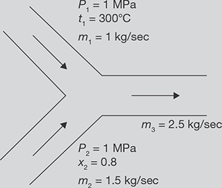
FIGURE 4.4
Mixing of Two Streams of Steam
SOLUTION
m2 = m3 − m1 = 2.5kg /sec− 1kg /sec = 1.5kg /sec.
From steady flow energy equation
At 1MPa, 3000 C, h1 = hg = 3051.2 kJ /kg
Putting the values of h1 and h2 in Equation 4.1
1kg × 3051.2 kJ /kg + 1.5kg × 2374.24 kJ /kg = 2.5 kg × h3
Now enthalpy at 1 MPa saturated steam = 2774.1 kJ /kg = hg
Hence, steam is wet steam
or, x = 0.9343
Saturation temperature at 1 MPa = 179.910 C
EXAMPLE 4.5
At 1.2 MPa, 250°C steam enters into a turbine and expands to 30°C. Determine the work output of turbine for 10 kg/s flow rate steam.
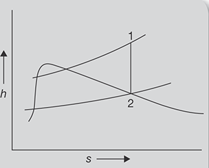
FIGURE 4.5
h-s Diagram
SOLUTION
h-s diagram for steam expansion is shown in Figure 4.5.
From steam table, at 1.2 MPa and 250° C
h1 = 2935kJ /kg, S1 = 6.8294 kJ /kgK
Since expansion is adiabatic, entropy remains constant
S1 = S2 = 6.8294 kJ /kgK
From saturated steam table, at 30°C
As S1 = S2, 6.8294kJ / kgK = 0.4369kJ / kgK + x(8.4533kJ / kgK − 0.4369kJ / kgK )
x = 0.7974
h2 = hf + xhfg = 125.79kJ / kg + 0.7974 × 2430.5kJ / kg = 2063.9382kJ / kg
Work output = h1 − h2 = 2935kJ / kg − 2063.93kJ / kg = 871.061kJ / kg
For 10 kg of steam = 10kg × 871.061kJ / kg = 8710.61kJ
EXAMPLE 4.6
1.0 kg wet steam of quality 0.7 at 0.3 MPa pressure is heated at constant pressure till the temperature rises to 300°C. Calculate the amount of energy added as heat.
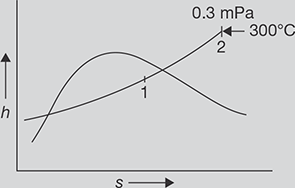
FIGURE 4.6
h-s Diagram
SOLUTION
h-s diagram for pressure rise of steam is shown in Figure 4.6
At point 1 in Figure 4.6
From Steam table
At 0.3 MPa and 300°C, from steam table; h2 = 3069kJ /kg
Heat added = h2 − h1 = 3069.3kJ /kg − 2076.13kJ /kg = 993.17 kJ / kg
EXAMPLE 4.7
A boiler of volume 10 m3 contains wet steam of quality 0.8 at 0.5 MPa pressure. The inlet and outlet valves of the boiler are closed and the energy addition as heat is stopped. After some time, the pressure of the steam is found to be 0.2 MPa.
Determine:
- the mass of liquid, the mass of vapor in the boiler at the beginning,
- the mass of liquid and mass of vapor in the boiler at the end, and
- the energy lost as heat to the surroundings.
From steam table, at 0.5 MPa, saturation temperature, ts = 151.86°C
Vf = 1.093 × 10⁻³ m3 / kg = 0.001093 m3 /kg
Vg = 0.379 m3 /kg, hf = 640.23 kJ /kg, hfg = 2108.5kJ / kg
Initial internal energy per kg is given by
Volume of the boiler is given by V1 = m{x1Vg1 + (1 − x1 )Vf1}, where m is mass of steam
10m3 = m × (0.8 × 0.3749 m3 + 0.2 × 0.001093m3 )
or, m = 33.342 kg.
- Thus, mass of steam = 33.42 kg × 0.8 = 26.6736 kg
Mass of water = 33.342 kg × 0.2 = 6.668 kg.
Suppose quality of steam at final state is x2, mx1Vg1 = mx2Vg2
Since value of Vf is negligible in the equation x1Vg1 + (1 − x1 )Vf1 = x2Vg2 + (1 − x2 )Vf2
From steam table, at 0.2 MPa,
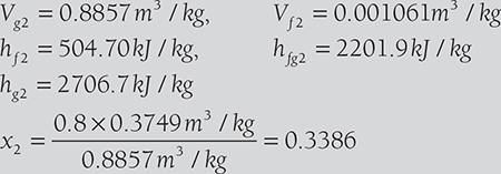
- b. Mass of steam = x2 (mw + mg ) = x2m = 0.3386 × 33.342 kg = 11.28 kg
Mass of water = 33.342 kg − 11.28 kg = 22.062 kg
- c. Final internal energy/kg at 0.2 bar is given by
u2 = (hf2 + x2hfg2 ) − x2P2Vg2 = (504.7 kJ /kg + 0.3386 × 2201.9kJ /kg)
− 0.3386 × 0.2 × 103 kPa × 0.8857 m3
= 1190.28 kJ / kg
Heat rejected = Change in internal energy during constant volume process
m(u1 − u2 ) = 33.342 kg(2177.07 kJ /kg − 1190.28 kJ /kg) = 32901.552 kJ
EXAMPLE 4.8
A pressure cooker contains 1 kg of saturated steam at 6 bar. Find the quantity of heat which must be rejected to reduce the quality of steam to 0.8. Determine the pressure and temperature of steam at the new state.
From steam table, at 6 bar, tsat = 158.8°5C
| Vf1 = 0.00101m3 / kg | Vg1 = 0.3157 m3 / kg |
| hf1 = 670.56kJ / kg | hfg1 = 2086.3 kJ / kg |
| hg1 = 2756.8 kJ / kg |
Volume of pressure cooker = 1kg × Vg1 = 1kg × 0.3157m3 /kg = 0.3157m3
Volume remains constant, hence, V1 = V2 = 0.3157m3
Initial internal energy of steam per kg = hg1 − P1Vg1
Now suppose quality of the steam at the end is x
V1 = V2 = 0.3157m3 = {(1 − x) × Vf2 + x × Vg2 } × 1kg = Vg2 × x
or, 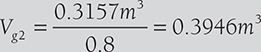
Pressure corresponding to 0.3946 m3/kg = 0.44 MPa (using linear interpolation in steam table value)
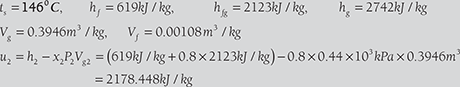
Total heat transfer = 2178.448kJ − 2567.38kJ = −1911kJ
EXAMPLE 4.9
4.3 THROTTLING CALORIMETER
Throttling calorimeter is a device used in the determination of the dryness fraction of steam. There is a sampling tube, which is placed in the steam main pipe. It consists of a hole facing upstream to get sample steam. The steam passes through the throttle valve and then flows into the inner cylinder. The main condition is that after throttling steam should be superheated. Normally, the degree of superheat should be 5°C. The pressure after throttling should be a few mm of Hg above atmospheric pressure as recorded by a manometer. The saturation temperature corresponding to this pressure can be found. If the temperature recorded by the thermometer is more than saturation temperature, it is confirmed that steam is superheated after throttling. Steam flows from the top of the inner cylinder to the annular space between inner and outer cylinders. The calorimeter is insulated from the surroundings. Before taking a temperature reading, the flow of the steam should be in the steady state and all parts to be heated to keep temperature remains constant. The constructional details of calorimeter are shown in Figure 4.7.
Let P1 = Initial pressure of steam
P2 = Final pressure = Atmospheric pressure + manometer reading
hf1 = Enthalpy of water at pressure, P1
hfg1 = Enthalpy of vaporization at pressure, P1
Cpg = Specific heat of superheated steam
tS2 = Saturation temperature at final pressure, P2
tsup = Temperature recorded by thermometer
x1 = Dryness fraction of steam before throttling
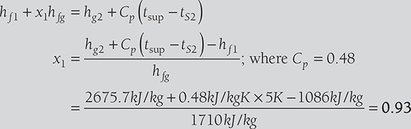
During throttling, enthalpy remains constant, i.e., enthalpy before throttling = enthalpy after throttling.

Therefore, hf1 + x1hfg = hg2 + Cp (tsup − tS2 )
or, 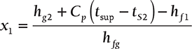 ; where Cp = 0.48
Limitation of the process is that the steam should be superheated after throttling.
EXAMPLE 4.10
A throttling calorimeter is used to measure the dryness fraction of the steam in steam main which has steam flowing at 10 bar. The steam after passing through the calorimeter is at 1 bar pressure and 120°C. Calculate the dryness fraction of the steam in the steam main. Take cps = 2.1 kJ/kgK.
SOLUTION
From steam table:
At pressure, P1 = 10 bar, hf1 = 762.81 kJ/kg, hfg1 = 2015.3 kJ/kg.
After throttling, at pressure, P2 = 1 bar, ts = 99.63°C, hg2 = 2675.5 kJ/kg.
Enthalpy remains constant during throttling process, Therefore, h1 = h2
762.81 kJ /kg + x × 2015.3 kJ /kg = 2675.5 kJ /kg + 2.1 kJ /kgK (120° C – 99.63° C)
4.4 SEPARATING AND THROTTLING CALORIMETER
A pure separating calorimeter suffers from a disadvantage that the steam passing out after water separation may not be completely dry, or it may have higher dryness fraction. Only in throttling calorimeter, a high dryness fraction (93%) can be found. Thus a combined separating and throttling calorimeter may be used to measure the dryness fraction of steam. The sample steam is first passed through separating calorimeter, where most of the moisture is separated and measured and then the dryer steam is passed into the throttling calorimeter. A schematic diagram of separating and throttling calorimeter is shown in Figure 4.8.
Let M = mass of steam passing through throttling calorimeter.
x2 = the dryness fraction entering into the throttling calorimeter that is determined by throttling calorimeter.
m = mass of water separated out in separating calorimeter.
x = dryness fraction of steam entering the separating calorimeter.
Thus, ![]()
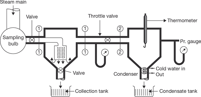
FIGURE 4.8
Separating and Throttling Calorimeter
EXAMPLE 4.11
Following data was obtained on combined separating and throttling calorimeter:
Pressure of steam sample = 20 bar, pressure steam at exit = 1 bar, temperature of steam at the exit = 160°C, discharge from separating calorimeter = 1 kg/min., discharge from throttling calorimeter = 15 kg/min. Determine the dryness fraction of the sample steam.
SOLUTION
Pressure of sample steam, P1 = P2 = 120 bar, pressure at the exit, P3 = 1 bar, temperature of steam at the exit, tsup3 = 180°C, discharge from separating calorimeter, m = 1 kg/ min., discharge of dry steam from throttling calorimeter, M = 15 kg/min.
At P1 = P2 = 20 bar, hf2 = 908.79 kJ/kg, hfg2 = 1890.7 kJ/kg.
At P3 = 1 bar and 160°C, h3 = hg3 = 2796.2 kJ/kg
or, 908.79kJ / kg + x2. 1890.7kJ / kg = 2796.2kJ / kg
4.5 STEAM TABLE
The properties of steam are pressure, temperature, volume, enthalpy, entropy, internal energy. These values are determined experimentally and tabulated as a steam table. Separate steam tables for saturated and superheated are used. If the temperature of the steam is more than the saturation temperature, it is known as superheated steam and the temperature difference of saturated steam and superheated steam is known as the degree of superheat. The steam tables for saturated and superheated steam are included in Appendix I of this book.
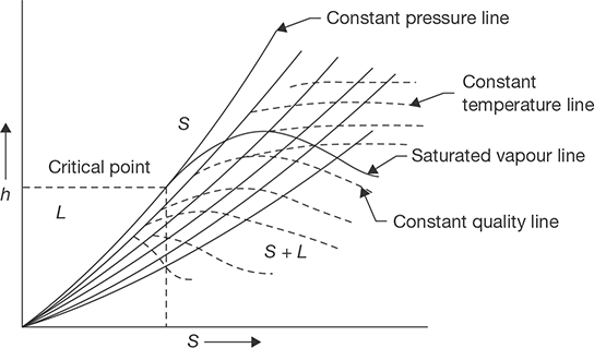
4.6 MOLLIER DIAGRAM OR h–S CHART
Mollier diagram is a graph between enthalpy and entropy. Various properties of steam can be shown graphically on this diagram. Natures of various lines are shown in Figure 4.9. A complete Mollier diagram is shown in Appendix II at the end of this book.
4.7 STEAM GENERATORS/BOILERS
The steam generator is a combination of apparatus, which is used in power generation and supply of steam in various plants. Its main purpose is to transfer the heat produced by fuel to water; water is converted into different types of steam as per requirements, such as wet steam, saturated steam, and superheated steam. A steam generator is also known as a boiler. It may be defined as “A combination of apparatus for producing, furnishing or recovering heat together with apparatus for transferring the heat so made available to water, which would be heated and vaporized to steam form” (ASME).
4.7.1 Classification of Boilers
There is a number of models of a boiler having different industrial applications. The boiler can be classified on the following basis:
- Contents inside the tube
- Firing system
- Position of drum
- Pressure
- Nature of water circulation
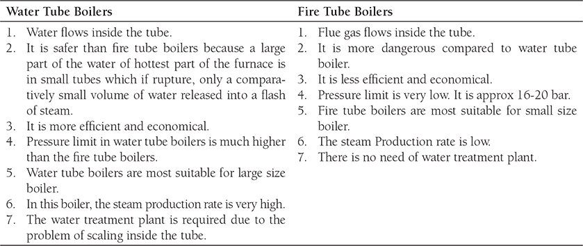
On the basis of contents of the tube, boilers can be classified as Fire tube boilers and water tube boilers. In fire tube boilers, flue gas passes through the tube and the heat of flue gas is absorbed by tube and transferred to water surrounding the tube, for example, Cochran boiler, Locomotive boiler, Lancashire boiler, and Cornish boiler. But, in water tube boilers, water flows inside the tube and tube is kept in the path of flow of flue gas, for example, Babcock and Wilcox Boiler, Benson boiler, Loffler boiler, etc. Most of the high-pressure boilers are water tube boiler. In this boiler, tube absorbs the heat of flue gas flowing surrounding the tube and transferred to water passing through the tube. The difference between water tube and fire tube boilers are given in Table 4.1.
Table 4.1: Differences between water tube boilers and fire tube boilers
On the basis of firing system, boilers can be classified as Internal Fired Boilers and External Fired Boilers. In internal fired boiler, firing takes place inside the boiler drum, i.e., furnace is located inside the drum, for example, Cochran boiler, Locomotive boiler, Lancashire boiler, etc. whereas in external fired boiler, furnace is outside the boiler drum and water is circulated inside the tube passing through the furnace, for example, Babcock and Wilcox Boiler.
On the basis of the position of the drum, boilers can be classified as a horizontal boiler, inclined boiler, and vertical boiler. On the basis of pressure, the boiler can be classified as a low-pressure boiler, high-pressure boiler, and super critical boiler. Low-pressure boilers operate below 80 bar; high-pressure boilers operate above 80 bar; and supercritical boilers operate at 221 bar and above. On the basis of the nature of the circulation of water, boilers can be classified as natural circulation boilers and forced circulation boiler. In natural circulation boilers, water circulates automatically due to the pressure difference created by the temperature difference. But, in forced circulated boilers, pumps are used to circulate the water through the tubes.
4.7.2 Requirements of a Good Boiler
A good boiler should have the following properties:
- Low cost of installation, operation, and maintenance
- Easy maintenance
- High efficiency
- Safety
- High transportability
- High steam production rate
- Good quality of steam
- Quick steam generation capacity
- Meeting fluctuating demand of steam, etc.
4.7.3 Cochran Boiler
It is fire tube, multitubular, internal fired and vertical boiler. Its maximum steam generation capacity is 3,500 kg/h. Its shell diameter and height are 2.75 meters and 5.8 meters, respectively. The fuel (coal) is fired on the grate in the furnace. The hot flue gas passes through the fire tube located in the water space and heat is transferred to the water. Water becomes hot in contact with the tube surface. Flue gas goes to the smoke box and finally in the atmosphere through the chimney. The circulation of water is natural; hot water rises up and cold water comes down as shown in Figure 4.10. The steam formed is collected at the upper space of the dome-shaped shell and supplied for use through a steam stop valve.

FIGURE 4.10
Cochran Boiler
The flames and hot gasses produced as a result of combustion of coal on the grate, rise in the dome-shaped combustion furnace. The unburnt fuel is reflected back to the grate and hot flue gas passes through the fire tubes and dissipates the heat to the water. Finally, the flue gas escapes into the atmosphere through smoke-box and chimney. Water circulation is natural circulation. Hot water rises up and cold water comes down continuously. Steam is collected in the upper space of the boiler.
4.7.4 Babcock and Wilcox Boiler
Babcock and Wilcox boiler is a water tube, horizontal, multitubular, external fired boiler. It covers a wide range of pressures compared to fire tube boilers. It has a steam generating capacity of 20,000 to 40,000 kg/h. It operates at an average 20–22 bar, but it can be operated at the maximum 40–42 bar. Its tubes are inclined at 5° to 15° for natural circulation. The diameter and length of tubes are designed as per requirement of the pressure of steam. Baffles are arranged normally for two or three passes of combustion gas. All mounting and accessories are shown in Figure 4.11, which is explained later in this chapter. There is a natural circulation of water. Water circulates from drum to tube and tube to drum with the help of downtake and uptake headers. To get superheated steam, the steam collected in the upper space of the drum is recirculated through superheater. The hot flue gas as a result of combustion rises up and moves in the direction as directed by the baffles. The tubes get exposure of hot gas and transfer the heat to the water flowing inside the tubes. Hot water rises and reaches into the boiler drum and cold water comes down into the tubes. Water circulates due to natural circulation produced by temperature differences.

FIGURE 4.11
Babcock and Wilcox Boiler
4.7.5 Locomotive Boiler
The locomotive boiler is a fire tube, horizontal, multitubular, natural circulation, movable, artificial draught, internal fired boiler. It meets the fluctuating demand of steam; its chimney height is very short. Artificial draught is created by supplying steam. It is generally used in a steam engine. The functions of all the mountings and accessories are discussed in the separate section of this chapter. The locomotive boiler is a movable boiler; therefore, its chimney is kept very small. A forced draught is created using the flow of steam. The flue gas passes through the tube as directed in Figure 4.12 and transfer the heat to the water through the tube walls.
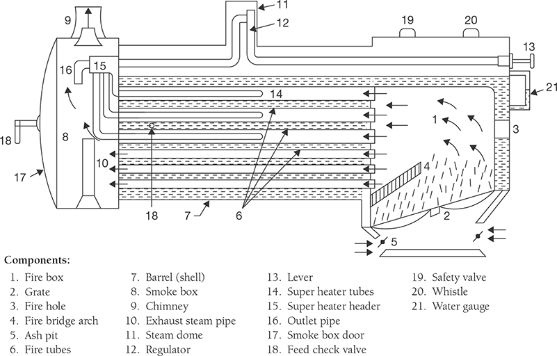
FIGURE 4.12
Locomotive Boiler
4.7.6 Lancashire Boiler
A Lancashire boiler is horizontal, fire tube, internal fired, natural circulation type boiler. There are two fire tubes. The fuel is burnt on the grate and the hot flue gas is produced. The flue gas moves along the furnace tubes and is deflected up by Fire Bridge. As soon as the flue gas reaches the back of main flue gas tubes, it deflects downwards and travels through the bottom flue gas tube as shown by arrows in Figure 4.13. The bottom flue is just below the water shell and heats the lower portion of the shell. After traveling from back to front, the flue gas bifurcates into separate paths in the side flues as shown by arrows in sectional side view. Now, it travels from front to back inside and heats the side of the water shell. These two streams of flue gas meet again in the main flue passing; through the damper, they are discharged to the atmosphere through the chimney.

FIGURE 4.13
Lancashire Boiler
4.7.7 Cornish Boiler
Cornish boiler is similar to Lancashire boiler, but the number of tube is only one. Also, the dimension of the drum is smaller than that of Lancashire boiler. Rests are similar construction and operation.
4.8 BOILER MOUNTINGS
Boiler mountings are the components of boilers, which are mounted on the body of the boiler for safety and controlling the steam generation processes. There are following components which are used as mountings in boiler operation:
1. Safety valve, 2. Water level indicator, 3. Pressure gauge, 4. Fusible Plug, 5. Steam stop valve, 6. Feed check valve, 7. Blow-off cock, 8. Man and Mudhole.
4.8.1 Safety Valves
The safety valve is used to release the excess pressure inside the boiler drum. When the pressure inside the drum exceeds the working pressure, safety valves blow-off the steam into the atmosphere. Generally, four types of safety valves are used in boilers: (i) Dead weight safety valve, (ii) Spring loaded safety valve, (iii) Lever safety valve, and (iv) High steam low water safety valve.
Dead Weight Safety Valve
Steam pressure acting in an upward direction is counterbalanced by the dead weight of safety valve acting in the downward direction. When the steam pressure exceeds the dead weight of safety valve, valve rises from its valve seat and steam escapes into the atmosphere. The construction of dead weight safety valve is shown in Figure 4.14. There is a vertical steam pipe having a valve seat at its mouth. A valve is fitted in the valve seat. Above the valve, a dead weight is applied. When the steam pressure becomes higher than the dead weight, valve rises from the valve seat and steam at high pressure is released into the atmosphere. Again, when the steam pressure becomes normal, i.e., less than dead weight, the valve returns to the valve seat.
Spring Loaded Safety Valve
This type of safety valve is spring loaded. Spring force works against the steam pressure, when the steam pressure becomes high, valve lifted off the valve seat and steam is escaped out. A lever is attached to one end of spring as shown in Figure 4.15. When steam pressure comes down valve returns to valve seat due to the force of spring.
Lever Safety Valve
The lever safety valve works on the principle of the second system of the lever as shown in Figure 4.16. In this valve, there is a lever which can rotate about a fulcrum, but its movement is limited by a guide. When the moment about fulcrum due to steam pressure exceeds the moment about fulcrum due to the weight applied on the lever valve is lifted off the seat and steam is escaped out. Again, the valve returns to its seat when the pressure becomes normal.
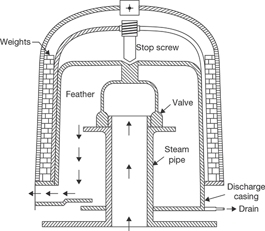
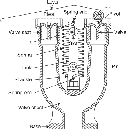
FIGURE 4.15
Spring Loaded Safety Valve
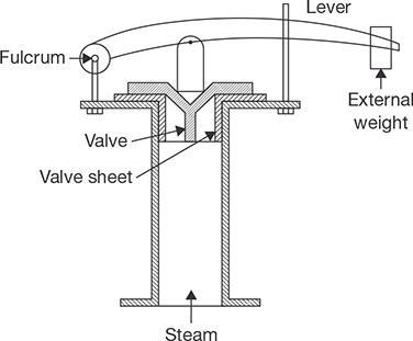
FIGURE 4.16
Lever Safety Valve
4.8.2 High Steam Low Water Safety Valve
There are following functions of high steam and low water safety valve:
- To blow out steam if steam pressure becomes higher than the working pressure.
- To blow out steam when the water level in the boiler comes down.
The constructional details of the high-pressure low water safety valve are shown in Figure 4.17. The arrangement of the outer valve is similar to that of the lever loaded valve. The balance or counterweight can be fixed at any position along the arm with a set screw. The arrangement of inner valve and dead weight acts as a dead weight safety valve. But, the load on the outer valve is both due to dead weight and strut thrust. If the steam pressure exceeds the limit, valve lifts and steam escapes to waste.
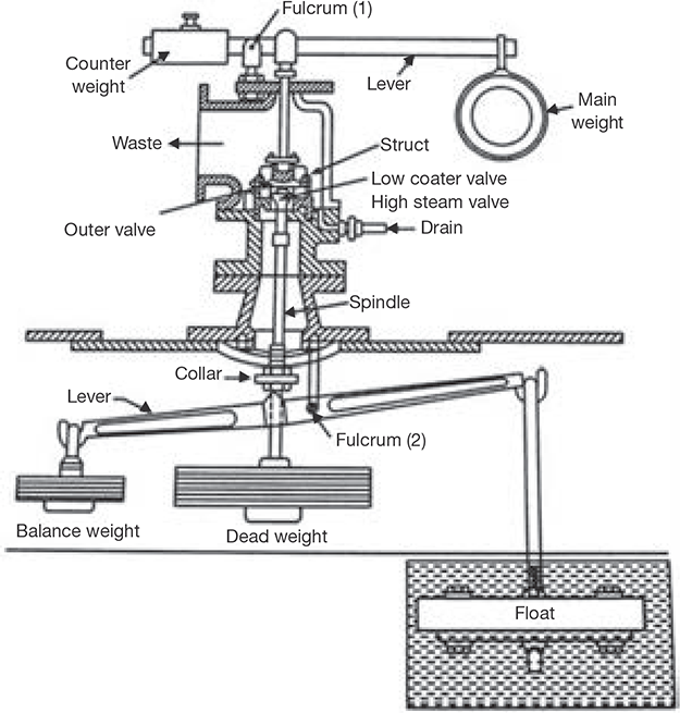
FIGURE 4.17
High Steam Low Water Safety Valve
The second lever is attached to a float at one end and a balance weight at the other end. When the float is submerged in water, the lever is balanced about the fulcrum. As soon as the float is uncovered, it gets unbalanced and tilts the lever towards the right. Due to tilting, it pushes the collar of the spindle in an upward direction and raising the valve from its seat. Thus, steam starts escaping through the waste pipe. A drain pipe is provided to drain out the condensed steam.
4.8.3 Water Level Indicator
The function of the water level indicator is to show the water level inside the boiler drum. Total two water level indicators are provided on the boiler drum. The constructional details are shown in Figure 4.18. One end of the glass tubes is connected to steam space and the other end to the water space through a hollow pipe of Gunmetal bolted to the boiler. In case, tube breaks, two balls are provided that move to the dotted positions due to the rush of water in the passage. The steam will also rush from the upward hollow column and will push the balls in dotted positions.

FIGURE 4.18
Water Level Indicator
4.8.4 Pressure Gauge
Pressure Gauge is used to measure the pressure inside the boiler drum. The constructional details are shown in Figure 4.19. There is a tube spring, one end of which is connected to the steam space and the other end is closed and connected to a link. The link is connected to toothed quadrant meshed with the pinion. At the center of the pinion, a pointer is fixed which can rotate with pinion. The quadrant rotates about the pivot and magnifies the reading. Due to steam pressure, spring tube tends to become straight and moves the pinion, which rotates the quadrant and pinion. The deflection in the pointer is shown on graduation on the disc, which shows the pressure of steam in the drum.
4.8.5 Feed Check Valve
The function of feed check valve is to allow the flow of water under pressure from the feed pump to the boiler and to prevent the back flow of water in case of failure of the feed pump. The constructional details are shown in Figure 4.20. The valve rises under pressure and water is allowed to flow inside the drum. The pressure of feed pump is more than that of steam inside the drum which allows the flow of water into the drum, but when supply is stopped, the valve returns to its seat due to steam pressure and prevents backflow of water. This is a one-way valve.

FIGURE 4.19
Pressure Gauge

FIGURE 4.20
Feed Check Valve
4.8.6 Steam Stop Valve
The function of steam stop valve is to stop or allow the flow of steam from the boiler to steam pipe or from the steam pipe to supply. The opening of the valve is controlled by a hand wheel. The constructional details of steam stop valve are very simple which is shown in Figure 4.21.
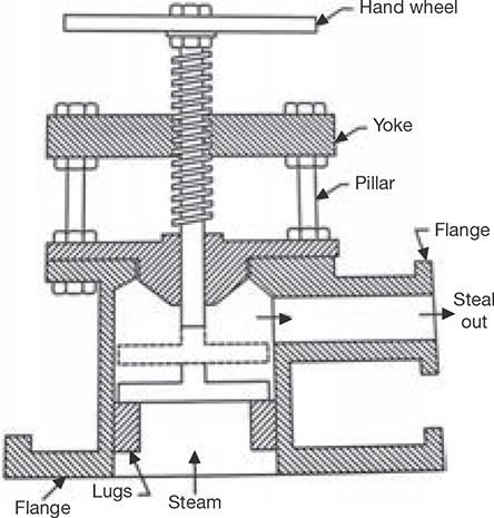
FIGURE 4.21
Steam Stop Valve
4.8.7 Blow-off Cock
The function of the blow-off cock is to blow down the sediments collected at the bottom of the drum or to empty the boiler or to lower down the water level in the drum. The blow-off cock is fitted at the lowest portion of the boiler. The casing is provided with two flanges, one is connected to the boiler and the other is connected to the steam pipe. The plug valve has a hole. When it is desired to discharge the water, the plug valve is turned in a manner so that the hole in the plug can align with the hole in casing and water can rush out of the boiler. The flow of water can be stopped by turning the plug such that its solid part comes in line with the hole in the casting. The constructional details are shown in Figure 4.22.
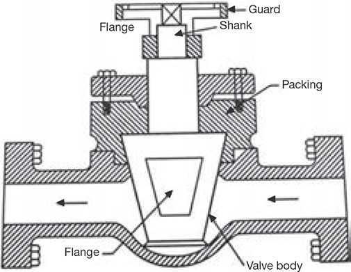
FIGURE 4.22
Blow-off Cock
4.8.8 Fusible Plug
The function of the fusible plug is to extinguish the fire in the fire box when the water level in the boiler comes down the limit. It prevents from blasting the boiler, melting the tube and overheating the firebox crown plate. The constructional details of the fusible plug are shown in Figure 4.23. It is located in the water space of the boiler. The fusible metal is protected from direct contact with water by Gunmetal and Copper plug. When water level comes down, the fusible metal melts due to high heat and copper plug drops down and holds in gun metal ribs. Steam comes in contact with fire and distinguishes it. Thus, it prevents from damages.
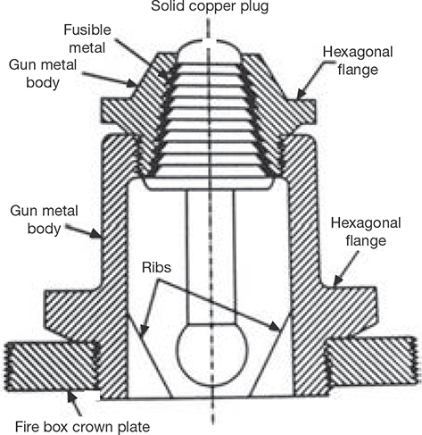
FIGURE 4.23
Fusible Plug
4.8.9 Manhole
This is opening in the boiler. It is used for cleaning and inspection purpose. Through this hole, the operator enters the boiler in idle condition.
4.9 BOILER ACCESSORIES
The devices used in a boiler to increase its efficiency and quality of steam are known as accessories. The names of some important accessories are mentioned below:
- Economizer,
- Air preheater,
- Super heater,
- Steam trap,
- Steam separator,
- Injector.
4.9.1 Economizer
Economizer is a type of heat exchanger which exchanges some parts of the waste heat of flue gas to the feed water. It is installed between the exit of the furnace and entry into the chimney. Generally, the economizer is placed after feed pump to avoid the problem of priming in feed pump. If the economizer is installed before feed pump, some amount of water may be transformed into vapor, which can create a priming problem in feed pump. In this case, limit of temperature rise of water is fixed so that water cannot be transformed into steam. The constructional details of economizer are shown in Figure 4.24. It consists of vertical cast iron tubes attached with scrapers. The function of the scraper is to remove the soot deposited on the tube. Water flows through the tube to the boiler drum. These tubes are arranged in the path of the waste flue gas entering into the chimney. The flow of water is controlled by two valves attached to down header and up the header of the tubes. The waste heat of the flue gas is transferred to the tube material and then tube material to water.
Advantages
- It increases the power output of the plant. For a 6°C increase in temperature of water efficiency of boiler increases by 1%.
- It increases the evaporation capacity.
- It increases the life of boilers due to less thermal stress.
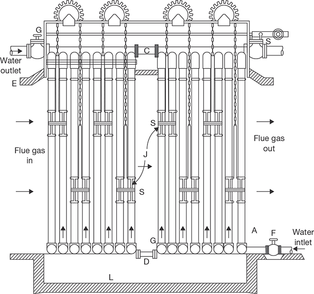
FIGURE 4.24
Economizer
4.9.2 Air Preheater
Air preheater is a device for recovery of waste heat from flue gas and is placed in the path of the waste flue gas going to the chimney. Waste heat if the flue gas is transferred to the air before its use to support economical combustion in a furnace. It is placed in the chimney and above economizer. If fuels used in the furnace are oil, gasses, or pulverized coal, the hot air supply is possible. But, in the case of stoker firing, the maximum temperature of the air is limited due to overheating of stoker parts. The constructional details of an air preheater are shown in Figure 4.25.
Advantages
- Due to high furnace temperature, water evaporation rate increase.
- Boiler efficiency increases by 2 to 10%.
- Low-grade fuel can be used.
Disadvantages
Capital cost increases due to use of preheater and two fans (induced fan and forced draught fan) to create an artificial draught.
4.9.3 Superheater
Steam generated in the boiler is wet due to contact with water. To get superheated steam, a device known as superheater is used in the boilers. The function of superheater is to superheat the steam up to the desired level. It is a surface heat exchanger, located in the path of the flue gas. The wet steam flows inside the tube and hot flue gas passed over the tubes. Constructional details of a superheater are shown in Figure 4.26.

FIGURE 4.25
Air Preheater
Advantages
- Superheater increases the efficiency of prime movers due to the supply of steam at high-temperature and pressure.
- It minimizes the condensation loss in a prime mover.
- It eliminates the problems of erosion and corrosion in turbine blades.
- It increases the capacity of the plant.
- It reduces the friction of the steam in a steam engine and other steam parts.
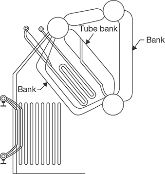
FIGURE 4.26
Superheater
4.9.4 Feed Pump
The function of feed pump is to feed the water to the boiler. Different types of feed pumps used in boilers are reciprocating, centrifugal, and injector. Centrifugal or rotary pumps are used where a large amount of water is required. For small boilers, reciprocating pump and injectors are used.
4.9.5 Injector
The injector is a feed pump which is used to deliver feed water into the boiler under pressure. It is mostly used in vertical and locomotive boilers. It is not suitable for large power plants. It consists of a group of nozzles so arrange that the steam expanding in these nozzles imparts kinetic energy to a mass of water. The constructional details of the injector are shown in Figure 4.27.
Advantages
- It requires minimum space.
- Maintenance cost is low.
- The initial cost of installation is low.
- It is thermally more efficient than feed pump.
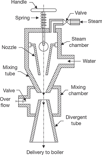
FIGURE 4.27
Steam Injector
4.9.6 Steam Trap
The function of a steam trap is to drain the water condensed due to partial condensation and jacket without allowing the steam to escape through it.
4.9.7 Steam Separator
The function of a steam separator is to separate the suspended water particles carried by steam on its way from the boiler to the engine of the turbine. It is installed in the mainstream pipe very near to the engine. The constructional details are shown in Figure 4.28.
The steam from the boiler enters the steam separator through a flange and moves down. During its passage down, it strikes the baffles and is deflected upward. The steam on striking the baffles causes the particles having the higher density to fall to the bottom of the separator with high inertia. Dry steam deflected up and comes out through the flange B. The separated water is collected at the bottom, which is drained out by drain cock and drain pipe.
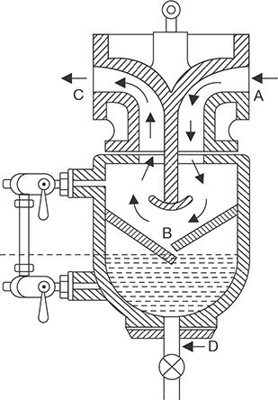
FIGURE 4.28
Steam Separator
4.9.8 Pressure Reducing Valve
The function of the pressure reducing valve is to maintain constant pressure on its delivery side of the valve irrespective of fluctuating demand of steam. This is achieved by throttling of steam passing through the pressure reducing valve. It is generally used in low capacity boilers where it is difficult to maintain constant delivery pressure with fluctuating demand of steam. In such a boiler, steam is generated at a higher pressure than the required by prime movers. The constructional details are shown in Figure 4.29. From boiler, high-pressure steam enters the steam inlet flange via throttle valve A to steam outlet flange. The throttling is done by a spring and valve rod mechanism. When the steam passes through the throttle valve, its pressure reduces. The force exerted by spring can be adjusted by a screw F. This varies the opening of the throttle valve so that any exit pressure required can be manipulated.
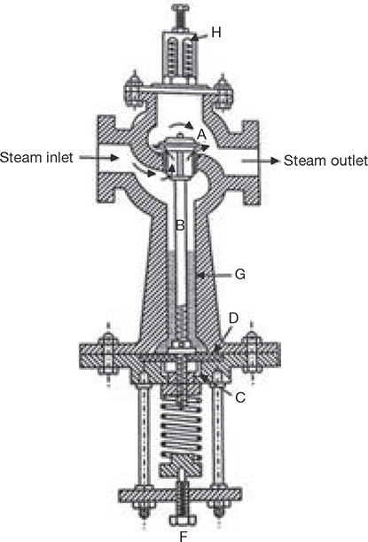
FIGURE 4.29
Pressure Reducing Valve
4.10 PERFORMANCE OF BOILERS
Evaporation Rate: it is the steam generation rate of boilers which may be expressed in terms of kg of steam per unit heating surface area or kg of steam per cubic meter of furnace volume or kg of steam per kg fuel burnt.
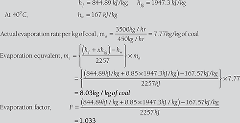
Equivalent Evaporation: It is equivalent of evaporation of 1 kg of water at 100°C to dry and saturated steam at 100°c, the standard atmospheric pressure of 1.013 bar. Hence, the equivalent evaporation of 1 kg of water at 100°C needs 2257 kJ.
Factor of Evaporation: It is the ratio of heat absorbed by 1 kg of feed water under working conditions to the latent heat of steam at atmospheric pressure.

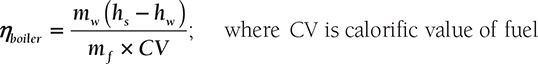
Boiler Efficiency: It is the ratio of heat absorbed by water in the boiler to heat supplied to boiler per unit time.
EXAMPLE 4.12
In a boiler trial observations made are as:
Calculate the evaporation factor and equivalent evaporation at 100°C in kg/kg of coal. Specific heat of feed water = 4.18 kJ/kgK.
SOLUTION
At 15 bar, (from steam table)
EXAMPLE 4.13
In a boiler observations made were as:
Calculate:
- boiler efficiency
- percentage of heat loss in flue gas
- percentage of heat loss to ash and unburnt coal
- percentage of heat loss unaccounted for.
SOLUTION
From steam table. At 10 bar,
Enthalpy of feed water at 30°C, hw = 125.79 kJ/kg
- ηboiler

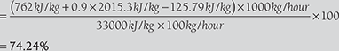
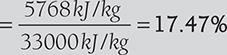
- Heat carried away by flue gas, Q = mfCf(tf − ta ) = 20kg × 1.03kJ/kg(300°C − 20°C)
= 5768kJ/kg of coal
hence, loss
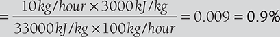
- Quantity of ash and unburnt coal = 10kg/hour
Heat lost in ash and unburnt coal
- Total heat accounted for = 74.24% + 17.47% + 0.9% = 92.61%
Heat unaccounted for = (100 − 92.61%) = 7.39%
EXAMPLE 4.14
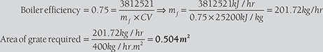
A boiler plant delivers steam at 20 bar and 360°C to an engine developing 1,350 kW at the rate of 10 kg/kWh. Temperature of feed water = 80°C. Calorific value of fuel = 28,000 kJ/kg. The grate is to be designed to burn 400 kg of coal per m2 per hour. Find the grate area required for the above duty, assuming the combustion efficiency of 90% and boiler efficiency including superheater as 75%.
SOLUTION
Enthalpy of steam at 20 bar and 360°C (from steam table),
hg = 3,159 kJ/kg (use interpolation)
hf = Enthalpy of feed water at 80°C = 334.91 kJ/kg
Mass of steam required to produce, 350 kW power = 1,350 × 10
Heat required = 13,500kg/hr (hg – hf) = 13,500kg/hr (3,159kg/hr – 334.91kg/hr)
Calorific value of fuel = 28,000 kJ/kg
But, combustion efficiency given as 90%
∴ Actual calorific value = 28,000kJ/kg × 0.9 = 25,200 kJ/kg
RECAP ZONE
Points to Remember
- Steam is a gaseous form of water.
- At very high pressure, latent heat of vaporization becomes zero, which is known as the critical point.
- Wet steam contains partly water as suspended in it and partly steam.
- Dryness fraction is defined as the mass of dry steam per kg of wet steam. It is represented by x.
- The properties of steam are pressure, temperature, volume, enthalpy, entropy, internal energy. These values are determined experimentally and tabulated as a steam table.
- Separate steam tables for saturated and superheated are used.
- Mollier diagram is a graph between enthalpy and entropy. Various properties of steam can be shown graphically on this diagram.
- Throttling calorimeter is a device used in the determination of the dryness fraction of steam. Wet steam is superheated using throttling process. To know the dryness fraction the enthalpy is balanced before and after throttling.
- Separating calorimeter is used to measure the dryness fraction by using the separation of water particle from the steam.
- In this process, the dryness fraction of the separated steam is very less compared to throttling calorimeter. Therefore, a combined device, i.e., separating and throttling calorimeter is used.
- In separating and throttling calorimeter, the separated steam is dried using throttling process.
- A combination of apparatus for producing, furnishing or recovering heat together with apparatus for transferring the heat so made available to water which would be heated and vaporized to steam form.
- In fire tube boilers, flue gas passes through the tube and the heat of the flue gas is absorbed by the tube and transferred to the water surrounding the tube.
- In water tube boilers, water flows inside the tube and the tube is kept in the path of flow of flue gas.
- In an internal fired boiler, firing takes place inside the boiler drum, i.e., furnace is located inside the drum.
- In an external fired boiler, the furnace is outside the boiler drum and water is circulated inside the tube passing through the furnace.
- Low-pressure boilers operate below 80 bar; high-pressure boilers operate above 80 bar; and supercritical boilers operate at 221 bar and above.
- In natural circulation boilers, water circulates automatically due to the pressure difference created by the temperature difference.
- In forced circulated boilers, pumps are used to circulate the water through tubes.
- Cochran boiler is fire tube, multitubular, internal fired and vertical boiler.
- Babcock and Wilcox boiler is a water tube, horizontal, multitubular, external fired boiler.
- Locomotive boiler is a fire tube, horizontal, multitubular, natural circulation, movable, artificial draught, internally fired boiler.
- A Lancashire boiler is horizontal, fire tube, internal fired, natural circulation type boiler. There are two fire tubes.
- Cornish boiler is similar to Lancashire boiler, but the number of the tube is only one.
- Safety valve is used to release the excess pressure inside the boiler drum.
- In a dead weight safety valve, the steam pressure acting in an upward direction is counterbalanced by the dead weight of safety valve acting in the downward direction.
- In a spring loaded safety valve, spring force works against the steam pressure, when the steam pressure becomes high, valve lifted off the valve seat and steam is escaped out.
- Lever safety valve works on the principle of the second system of the lever.
- The functions of high steam and low water safety valve are:
- To blow out steam if steam pressure becomes higher than the working pressure.
- To blow out steam when the water level in the boiler comes down.
- The function of the water level indicator is to show the water level inside the boiler drum.
- Pressure gauge is used to measure the pressure inside the boiler drum.
- The function of feed check valve is to allow the flow of water under pressure from the feed pump to the boiler and to prevent the backflow of water in case of failure of the feed pump.
- The function of steam stop valve is to stop or allow the flow of steam from the boiler to steam pipe or from the steam pipe to supply.
- The function of the blow-off cock is to blow down the sediments collected at the bottom of the drum or to empty the boiler or to lower down the water level in the drum.
- The function of the fusible plug is to extinguish the fire in the fire box when the water level in the boiler comes down the limit.
- A manhole is used for cleaning and inspection purpose.
- Economizer is a type of heat exchanger, which exchanges some parts of the waste heat of flue gas to the feed water.
- Air preheater is a device for recovery of waste heat from flue gas and is placed in the path of the waste flue gas going to the chimney.
- The function of superheater is to superheat the steam up to the desired level.
- The function of feed pump is to feed, the feed water to the boiler.
- The injector is a feed pump, which is used to deliver feed water into the boiler under pressure.
- The function of a steam trap is to drain the water condensed due to partial condensation and jacket without allowing the steam to escape through it.
- The function of a steam separator is to separate the suspended water particles carried by steam on its way from the boiler to the engine of the turbine.
- The function of the pressure reducing valve is to maintain constant pressure on its delivery side of the valve irrespective of fluctuating demand of steam.
- Draught is a small pressure difference causing the flow of flue gas and air through the boilers.
- Natural draught is a pressure difference of the hot gasses column inside the chimney and cold air column of the same height outside the chimney.
- If a mechanical induced fan is used at the base of the chimney to suck the air and flue gasses from the furnace, the draught created is known as induced draught.
- If a mechanical fan is installed at the gate of the furnace to force the air inside the furnace, the draught created is known as forced draught.
- If both forced draught and induced draught fans are used in a boiler, the draught created is known as balance draught.
- Evaporation rate is the steam generation rate of boilers, which may be expressed in terms of kg of steam per unit heating surface area or kg of steam per cubic meter of furnace volume or kg of steam per kg fuel burnt.
- Equivalent evaporation is equivalent of evaporation of 1 kg of water at 100°C to dry and saturated steam at 100°c, the standard atmospheric pressure of 1.013 bar.
- Factor of evaporation is the ratio of heat absorbed by 1 kg of feed water under working conditions to the latent heat of steam at atmospheric pressure.
- Boiler efficiency is the ratio of heat absorbed by water in the boiler to heat supplied to boiler per unit time.
Important Formulae


REVIEW ZONE
Multiple-choice Questions
- Device used to generate and supply steam at a high pressure and temperature is known as:
- Steam injector
- Steam boiler
- Steam turbine
- Steam condenser
- Fire tube boilers are:
- Internally fired
- Externally fired
- Both
- None of the above
- Fire tube boilers are:
- Lancashire boiler
- Cochran boiler
- Locomotive boiler
- All of the above
- Number of fire tubes in Lancashire boiler are:
- 1
- 2
- 3
- 4
- In a Lancashire boiler, the economizer is located:
- Before air preheater
- After air preheater
- Between the feed pump and drum
- All of the above
- Locomotive boiler is:
- Vertical, multitubular, fire-tube type
- Horizontal, multitubular, fire-tube type
- Horizontal, multitubular, water-tube type
- None of the above
- Water tube boiler is:
- Babcock and Wilcox boiler
- Stirling boiler
- Benson boiler
- All of the above
- Babcock and Wilcox boiler has water tubes:
- Vertical
- Horizontal
- Inclined
- None of the above
- If circulation of water takes place by convection currents, set up during the heating of water, the boiler is known as:
- Natural circulation boiler
- Forced circulation boiler
- Internally fired boiler
- Externally fired boiler
- If circulation in boiler made by pump, then it is known as:
- Natural circulation boiler
- Forced circulation boiler
- Internally fired boiler
- Externally fired boiler
- If combustion takes place outside the boiling water region, the boiler is known as:
- Natural circulation boiler
- Forced circulation boiler
- Internally fired boiler
- Externally fired boiler
- If combustion takes place inside the boiling water region, the boiler is known as:
- Natural circulation boiler
- Forced circulation boiler
- Internally fired boiler
- Externally fired boiler
- In forced circulation boiler, forced is applied to:
- Draw water
- Drain off the water
- Circulate water
- All of the above
- Forced circulation boiler is:
- La-Mont boiler
- Benson boiler
- Loeffler boiler
- All of the above
- Safety Valve used in locomotive boilers is:
- Lever safety valve
- Dead weight safety valve
- High steam and low water safety valve
- Spring loaded safety valve
- A device used to empty the boiler, when required and to discharge the mud, scale or sediments collected at the bottom of the boiler, is known as:
- Safety valve
- Stop valve
- Fusible plug
- Blow off cock
- An accessory of boiler is:
- Feed pump
- Feed check valve
- Stop valve
- Blow off cock
- A device used for recovery of waste heat of flue gas to heat the air before it passes into the furnace is known as:
- Superheater
- Air preheater
- Injector
- Economizer
- Boiler mounting is:
- Economizer
- Injector
- Fusible plug
- Super heater
- Ratio of heat used in steam generation and heat supplied to the boiler is known as:
- Boiler efficiency
- Chimney efficiency
- Economizer efficiency
- None of the above
- At very low-temperature at which melting and boiling point of water becomes equal is:
- 233 K
- 273.16 K
- 303 k
- 0 K
- The critical pressure at which latent heat of vaporization of water becomes zero is:
- 225.65 bar
- 273 bar
- 100 bar
- 1 bar
- For water, below the atmospheric pressure:
- Melting point rises slowly and boiling point drops markedly
- Melting point drops slowly and boiling point rises markedly
- Melting point rises slowly and boiling point rises markedly
- None of these
- The latent heat of steam at pressure greater than atmospheric pressure than that at atmospheric pressure is:
- Less
- More
- Equal
- None of these
- The saturation temperature of steam with increasing in pressure increases:
- Linearly
- First rapidly then slowly
- Inversely
- None of these
- Heating of dry steam above saturation temperature is known as:
- Enthalpy
- Superheating
- Supersaturating
- None of these
- Superheating of steam is done at:
- Constant volume
- Constant pressure
- Constant enthalpy
- Constant entropy
- The specific volume of steam with increase in pressure decreases:
- Linearly
- Slowly first and then rapidly
- Rapidly first and then slowly
- Inversely
- If x1 and x2 be the dryness fractions obtained in separating calorimeter and throttling calorimeter respectively, then the actual dryness fraction of steam will be:
- x1x2
- x1+x2
- (x1+x2)/2
- x1/x2
- The specific heat of superheated steam in kCal/kg is generally of the order of:
- 0.1
- 0.3
- 0.5
- 0.8
- A wet steam can be completely specified by:
- Pressure only
- Temperature only
- Dryness fraction only
- Pressure and dryness fraction
- On Mollier chart, the constant pressure lines:
- Diverge from left to right
- Diverge from right to left
- First, rise up and then fall
- None of these
- On Mollier diagram, free expansion, or throttling process from high pressure to the atmosphere is represented by:
- Horizontal straight line
- Vertical straight line
- Curved line
- None of these
- Latent heat of dry steam at atmospheric pressure is equal to:
- 539 kCal/kg
- 539 kJ/kg
- 539 BTU/lb
- None of these
- In throttling process:
- Entropy remains constant
- Enthalpy remains constant
- Pressure remains constant
- None of these
Fill in the Blanks
- 36. Water tube boilers produce steam at a _________ pressure than that of fire tube boilers.
- 37. For same dimensions and thickness of the tube, a water tube boiler has _________ heating surface than a fire tube boiler.
- 38. A _________ in a boiler is used to put off a fire in the furnace when the level of water falls to the unsafe limit.
- 39. An equivalent evaporation of a boiler is defined as _________.
- 40. The draught in the locomotive boiler is produced by _________.
Answers
- b
- c
- d
- b
- b
- b
- d
- c
- a
- b
- d
- c
- c
- d
- d
- d
- a
- b
- c
- a
- b
- a
- a
- a
- b
- b
- b
- c
- a
- c
- d
- a
- a
- a
- b
- Higher
- More
- Fusible plug
- The amount of water evaporated from and at 100°C to dry and saturated steam
- Passing the steam through the furnace
Theory Questions
- * Define dryness fraction and degree of superheat and show their applications in a steam power plant.
- Explain the use of steam table and Mollier diagram.
- * Draw a neat sketch of throttling calorimeter and explain how dryness fraction of steam is determined. What are its limitations?
- What are requirements of a good boiler?
- Differentiate between (i) Natural circulation and forced circulation in boilers, (ii) Internal fired and external fired boilers, (iii) Fire tube and water tube boilers, and (iv) High-pressure and low-pressure boilers.
- Explain very briefly the function of following mountings:
- Steam stop valve
- Feed check valve
- Blow-off cock
- water level indicator
- Pressure gauge
- Safety valve
- State the advantages of high-pressure boilers. Explain the construction and working of Babcock and Wilcox boiler with a neat sketch.
- Explain the construction and working of a pressure gauge with a neat sketch.
- Explain the working of Cochran boiler and fusible plug with neat sketches.
- * State the function of following:
- Fusible plug
- Safety valve
- Economizer
- * What is boiler? Discuss Construction and working of Cochran boiler with neat sketch.
- * Write a short note on Separating calorimeter with its limitations.
- * Define boiler according to IBR. Classify mountings into safety fittings and control fittings.
- * Describe the functions of chimney in a boiler.
- * Name all the mountings and accessories of a steam boiler and describe, with neat sketch, the working of any one of each.
- * Explain economizer and air-preheater with neat sketch.
- * Show the function and location of the following in the boiler plant:
- Feed check valve
- Air superheater, and
- Fusible plug.
- * Enumerate the advantages and disadvantages of superheated steam.
- * Explain briefly air preheater, superheater, and chimney with respect to boilers.
- * Explain with neat sketch and working principle of Lancashire boiler.
Numerical Problems
- A pressure cooker contains 0.5 m3 water and water vapor mixture at 300°C. Calculate the mass of each if their volumes are equal.
- Steam flows through a pipe at the rate of 5 kg/s. The pressure and temperature are 12 bar and 300°C, respectively. If 2,000 kJ of heat is lost to the surroundings at constant pressure. Find the final condition of steam.
- A container is filled with a saturated steam at 12 bar. The volume of the container is 1 m3. First, the container is evacuated, then necessary amount of water is filled and evaporated by heating:
- What mass of water is required and what will be the temperature of water.
- If the container, finally, contains a two-phase system with a dryness fraction of 85%. What will be the required mass?
- 10 kg of wet steam of quality 0.8 at 5 bar pressure is heated at constant pressure till the temperature rise is 500°C. Calculate the amount of energy added as heat.
- A boiler of volume 1 m3 contains wet steam of quality 0.85 at 10 bar. The inlet and outlet valves of the boiler are closed and energy addition as heat is stopped. After some time, the pressure of steam is found 4 bars. Determine:
- the mass of liquid and vapor in boiler initially,
- the mass of liquid and vapor in the boiler at the end, and
- energy lost to the surrounding as a heat.
- A pressure cooker contains 10 kg of saturated steam at 8 bar. Find the quantity of heat which must be rejected to reduce the quality to 85%. Determine the pressure and temperature at the new state.
- Determine the enthalpy and internal energy of 1 kg steam at a pressure of 10 bar, when (i) the dryness fraction of steam is 0.85, (ii) the steam is superheated to 300°C, and (iii) when steam is dry and saturated. Neglect the volume of water and take the specific heat of superheated steam as 2.1 kJ/kgK.
- Determine dryness fraction of steam supplied to a separating and throttling calorimeter.
Water separated in separating calorimeter = 0.45 kg
Steam discharged from throttling calorimeter = 7 kg
Steam pressure in the main pipe = 1.2 MPa Barometer reading = 760 mm of Hg Manometer reading = 180 mm of Hg
Temperature of steam after throttling = 140°C;
Cp = 2.1 kJ/kgK
- A steam generator evaporates 17,000 kg/h of steam at 14 bar and quality of 0.95 from feed water at 102°C. When coal is fired at the rate of 2,050 kg/h having a calorific value of 27,400 kJ/kg. Assume the specific heat of water as 4.187 kJ/kgK. Calculate: (i) Heat supplied per hour, (ii) Thermal efficiency, and (iii) Equivalent evaporation.
- Determine dryness fraction of steam supplied to a separating and throttling calorimeter.
Water separated in separating calorimeter = 0.2 kg
Steam discharged from throttling calorimeter = 1.8 kg
Steam pressure in main pipe = 9 bar
Steam pressure after throttling = 1 bar
Temperature of steam after throttling = 115°C;
Cp = 2.1 kJ/kgK
- A boiler generates 7.5 kg of steam per kg of coal burnt at a pressure of 11 bar. The feed water temperature is 70°C; boiler efficiency is 75%; factor of evaporation is 1.15; Cp = 2.1 kJ/kgK. Calculate: (i) degree of superheat and temperature of steam generated, (ii) calorific value of coal in kJ/kg, and (iii) equivalent evaporation in kg of steam per kg of coal.
- What height of chimney is required to produce a draught of 20 mm of water column, if 15 kg of air is required to burn 1 kg of coal? The mean temperature of gas inside the chimney is 300°C and that of atmospheric air is 35°C.
- Calculate the mass of air required to burn per kg of coal for chimney height of 40 mm. Draught produced is 24 mm of water. The temperature of flue gas inside the chimney is 350°C and that of the air outside the chimney is 20°C. Also, calculate the drought produced in term of hot flue gas column.
- In a boiler observations made were as:
Rate of feed water per hour = 800 kg
Temperature of feed water = 30°C
Steam pressure = 12 bar
Quality of steam = 0.95
Coal consumption rate per hour = 100 kg
Calorific value of coal = 32,000 kJ/kg
Mass of ash and unburnt coal = 10 kg/h.
Calorific value of ash and unburnt coal = 3,000 kJ/kg
Quantity of flue gas/kg of coal = 20 kg
Discharged gas temperature = 350°C
Atmospheric temperature = 25°C
Specific heat of flue gas = 1.03 kJ/kgK.
Calculate:
- boiler efficiency
- percentage of heat loss in flue gas
- percentage of heat loss to ash and unburnt coal
- percentage of heat loss unaccounted for.
- In a boiler trial observations made are as:
Feed water temperature = 30°C Boiler pressure = 12 bar Dryness fraction of steam = 0.80 Coal consumption = 400 kg/h Feed water supplied = 3,000 kg/h Calorific value of coal = 38,000 kJ/kg Calculate the evaporation factor and equivalent evaporation at 100°C in kg/kg of coal. Specific heat of feed water = 4.18 kJ/kgK.
- * How much heat is to be added to convert 4 kg of water at 20°C in to steam at 8 bar and 200°C. Take Cp of superheated steam as 2.1 KJ/kg and specific heat of water as 4.187 KJ/kg/K.
- * What do you understand by mechanical and thermal efficiency? A steam plant uses 3 tonne of coal/h. The steam is fed to turbine the output of which is 4 MW. The calorific value of the coal is 30 MJ/kg calculate the thermal efficiency of the plant.
- * Determine the quality of steam for the following cases:
- P = 10 bar, v = 0.180 m3/kg
- P = 10 bar, t = 200°C
- P = 25 bar, h = 2,750 kJ/kg
- * Combined separating and throttling calorimeter is used to find out dryness fraction of steam, following readings were taken:
Main pressure = 12 bar abs.
Mass of water collected in separating calorimeter = 2 kg.
Mass of steam condensed in throttling calorimeter = 20 kg
Temperature of steam after throttling calorimeter = 110°C
Pressure of steam after Throttling = 1 bar abs.
Assume Cp of steam = 2.1 kJ/kg K.
Calculate dryness fraction.
- * Determine the quality of steam for the following cases:
- P = 10 bar, v = 0.180 m3/k
- P = 10 bar, t = 200°C
- P = 25 bar, h = 2,750 kJ/kg
- * Steam at 1,000 kPa and 300°C enters an engine and expands to 20 kPa. If the exhaust steam has a dryness fraction of 0.9, make calculations for the drop in enthalpy and change in entropy.
- * Determine the total heat content per unit mass at the following state using the steam tables. Assume ambient pressure to be 100 kPa and CP = 2.0934 kJ/kg.
- 10 bar absolute and 300°C
- 100 kPa gauge and 100 kPa abs and 250 L,C
- Dry steam at 100 kPa abs
- Steam at 12 bar and 95% dry
- * Determine the specific volume and density of I kg steam at a pressure of 7 × 10⁵ Pa, when the condition of steam is: (i) Wet, having dryness fraction 0.9, (ii) Dry, and (iii) Superheated at 250°C. If required use the extract of the steam table provided below:
P ts Vg 7 bar 437.92K 0.27334 m3/kg - * Determine enthalpy and internal energy of 1 kg of steam at a pressure of 12 bar when: (i) the dryness fraction of steam is 0.8, (ii) steam is dry and saturated, and (iii) steam is superheated to 2,800°C. Take Cps = 2.1 kJ/kg K.
- * Calculate the internal energy per kg of superheated steam at 10 bar and a temperature of 300°C. Find, also change in internal energy if this steam is expanded to 1.4 bar and dryness fraction 0.8.