
CHAPTER 12
Stress and Strain
Learning Objectives
By the end of this chapter, the student will be able:
- To demonstrate the Hook’s law
- To describe the behaviour of the engineering materials under different types of loadings
- To calculate the stress and strain produced in a material under different types of loading
- To understand the concepts of principal stress and strain
- To demonstrate the Mohr’s circle for principal stress and principal strain
12.1 INTRODUCTION
There are certain behaviors of all materials under the influence of an external force. Stress and strain are one of the measures to show these behaviors. Stress is a resistive force per unit area, which is developed internally to oppose the external force subjected to the material. The strain is a measure of deformation of the material per unit dimensions. If the stress developed in the material is perpendicular to the cross-section, it is known as direct stress and if it is tangential or parallel to the cross-section, it is known as shear stress.
In Figure 12.1 (a), a cylindrical job is subjected by a load P. If the specimen is broken at AB, the same amount of stress will be developed for equilibrium at the section AB which is known as direct stress. Direct stress can be explained as average stress and normal stress. Since stress is force developed per unit area. It is not necessary that amount of force on every point on cross-section AB will be same. It depends on direction and point of application of external force P, so it is known as average stress (σ).
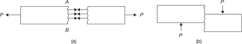
FIGURE 12.1
(a) Cylindrical Job Subjected to Axial Load and (b) Cylindrical Job Subjected to External Load Parallel to Cross-section

If the stress distribution along the cross-section is uniform, it is known as simple or normal stress. σ = P/A. To develop normal stress, the external force P must be passed through the centroidal axis.
In Figure 12.1 (b), an external load P is subjected to the specimen parallel to the cross section. There will be resistance just opposite to the external load which is parallel to the cross section and known as shear force. Again shear stress distribution may or may not be uniform along the cross-section.
Strain is a way to show the deformation in the material. In Figure 12.2, the deformations are shown in two directions: one in the direction of load application and other in the direction perpendicular to load application. The strain produced in the direction of load is known as longitudinal strain and the strain produced perpendicular to load application is known as lateral strain.
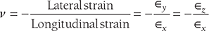
The ratio of lateral to longitudinal strain is constant which is known as Poisson’s ratio (v).
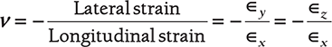
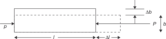
FIGURE 12.2
Longitudinal and Lateral Strain
The value of v for steel ranges from 0.25 and 0.33.
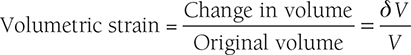
Volumetric strain,  Superficial strain,
  where ΔV is the change in volume, V is original volume, ΔA is a change in the area, and A is the original area.
12.2 HOOKE’S LAW
Hook’s law states that stress and strain are perpendicular to each other under the elastic limit. Originally, Hooke’s law specified that stress was proportional to strain but Thomas Young introduction a constant of proportionality which is known as Young’s modulus. Further, this name was superseded modules of elasticity.
Where E is the modulus of elasticity; σ is stress, and ∈ is a strain.
12.3 STRESS–STRAIN DIAGRAM
Hooke’s law states that stress and strain are proportional to each other under the elastic limit. Originally, Hooke’s law specified that stress was proportional to strain but later Thomas Young introduced a constant of proportionality which is known as Young’s modulus of elasticity. Further, this name was superseded by the modulus of elasticity. Figure 12.3 demonstrates the Hooke’s Law.

FIGURE 12.3
Hook’s Law
Working Stress, Allowable Stress, and Factor of Safety: Working stress is defined as the actual stress of a material under a given loading. The maximum safe stress that a material can carry is termed as the allowable stress. The allowable stress should be limited to values not exceeding the proportional limit. However, since the proportional limit is difficult to determine accurately, the allowable stress is taken as either the yield point or ultimate strength divided by a factor of safety. The ratio of this strength (ultimate or yield strength) to allowable strength is called the factor of safety.
The relationship between gauge length and cross-sectional area of the tensile test specimen can be given as ![]() , where A is an area of cross-section.
, where A is an area of cross-section.
Note: Stress-strain diagram for medium carbon steel refer Ch.17.
EXAMPLE 12.1
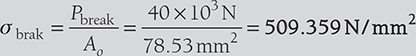
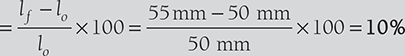
A mild steel specimen with an original diameter of 10 mm and a gauge length of 50 mm was found to have an ultimate load of 60 kN and breaking load of 40 kN. The gauge length at rupture was 55 mm and diameter at rupture cross-section was 8 mm. Determine: (i) the ultimate stress, (ii) Breaking stress, (iii) True breaking stress, (iv) percentage elongation, and (v) percentage reduction in area.
SOLUTION
Given: lg = 50 mm, do=10 mm, lf = 55 mm, Pult = 60 kN, Pbreak = 40 kN, and df = 8mm.
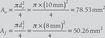
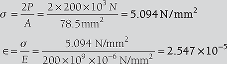
- Ultimate stress,

- Breaking stress,
- True breaking stress,

- Percentage elongation
- Percentage reduction in area

Stress and Strain in Simple Stepped Bar

Let us consider a stepped bar of diameters d1, d2, and d3 as shown in Figure 12.4 (a). Different forces of the magnitude of P1, P2, P3, and P4 are acting at a different section of the bar. Free body diagram of these sections are shown in Figure 12.4 (b).
For section AB: 
For section BC: 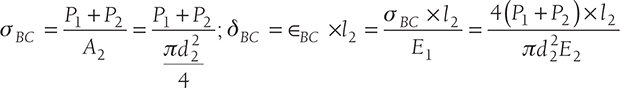
For section CD: 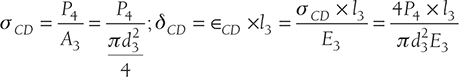
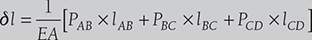
Here δ is total deflection in the bar.
EXAMPLE 12.2
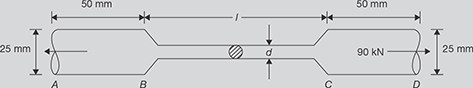
There is a specimen for a tensile test of a material. It has a circular cross-section and enlarged ends as shown in Figure 12.5.
The total elongation is 10 mm. The lengths of the enlarged ends are equal to 50 mm and diameter 25 mm for each end. The length and diameter of the middle portion are to be found. The tensile loads applied at the ends are 90 kN and stress produced in the middle portion is 450 MN/m2. Find the length l and diameter d for the middle portion of the specimen. E = 2 × 10⁵ MPa.
SOLUTION
Cross-section area of the middle portion ![]()
Stress produced in the middle portion = 450 × 106N/m2 
or, 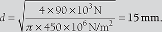
Elongation produced in the end portions of the specimen
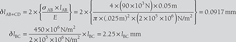
Total elongation, δl = 10 mm = δlAB + δlCD + δlBC = 0.0917 mm + 2.25 × lBC
or lBC = 4.40 mm
EXAMPLE 12.3
A brass rod in static equilibrium is subjected to axial load as shown in Figure 12.6:

FIGURE 12.6
A Bar Under Static Equilibrium
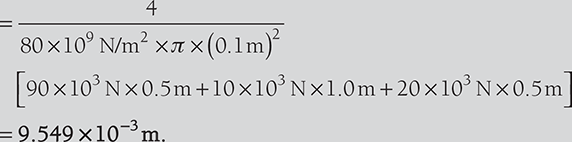
Find the load P and change in length of the rod if its diameter is 100 mm. Take E = 80 GN/m2.
SOLUTION
Draw the free body diagram for each part of the rod as shown below:

FIGURE 12.7
Free Body Diagram
Change in length, ![]()
12.4 EXTENSION IN VARYING CROSS-SECTION OR TAPER ROD
A rod of length l tapers uniformly from a diameter D at one end to diameter d at another end as shown in Figure 12.8. Considering a small element of thickness dx at distance x from the end of diameter d. the diameter of the element is calculated as ![]()

FIGURE 12.8
Extension in Taper Rod
Extension in the element of length 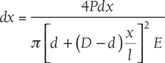
Total extension in the bar, 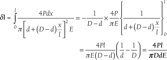
EXAMPLE 12.4
A rod tapers uniformly from 50 mm to 20 mm diameter in a length of 500 mm. If the rod is subjected to an axial load of 10 kN, find the extension in the rod. Assume E = 2 × 10⁵ MPa.
SOLUTION
D = 0.05 m, d = 0.02 m, l = 0.5 m, P = 10 × 103 N, and E = 2 × 10¹¹ N/m2.
EXAMPLE 12.5
Determine the elongation of a conical bar under the action of its own weight, if the length of the bar is L, the diameter of the base is D and the weight per unit volume of the material is ρ.
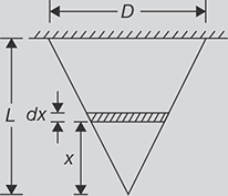
FIGURE 12.9
Conical Bar
SOLUTION
Consider a section of small length dx at a height x from the apex cone (as shown in Figure 12.9) where the diameter is ![]() , and weight of the cone below the section
, and weight of the cone below the section ![]()
Elongation in the section 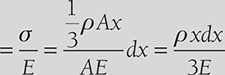
Total elongation of the bar, 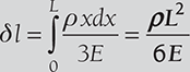
12.5 STRESS AND STRAIN IN VARYING CROSS-SECTION BAR OF UNIFORM STRENGTH
Consider a bar of varying cross-section of uniform strength subjected by a longitudinal stress σ as shown in Figure 12.10. Now consider a small element of axial length δx at a distance of x from smaller end. Let, the area of the cross-section at section x be A and at section x + δx be A + δA. For the element of length δx to be in equilibrium, the total downward force must be equal to the total upward force acting on it.
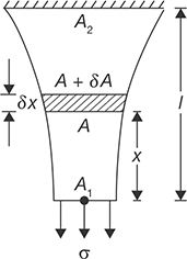
FIGURE 12.10
Varying Cross-section Bar of Uniform Strength
Weight of length δx + tensile stress at section x × area at section x = Tensile stress at section (x + δx) × area at section (x + δx)
Here, δW is vertical weight due to weight of free body = ρ × g × A × δx where ρ is the density of material of the bar.
Thus, 
or, ![]()
On integration, between area A1 and A
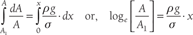
Hence, 

or, 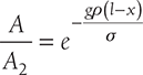 or,
or, 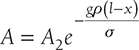
Let de be the extension in a small length dx.
EXAMPLE 12.6
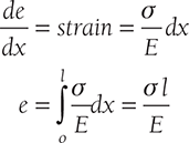
A bar of uniform strength is shown in Figure 12.11:
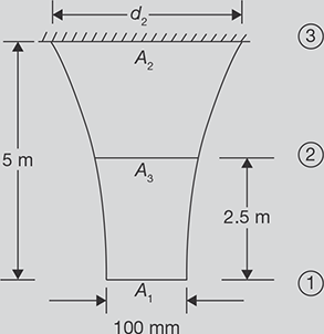
FIGURE 12.11
Bar of Uniform Strength
Its length is 5 m, diameter at bottom edge is 100 m, weight density of bar is 0.07644 × 10⁻³ N/mm2. It is subjected to a uniform stress 0.6 N/mm2. Find the diameters at the top and at the half of its length.
SOLUTION
Given d = 100 mm, l1 = 5 m, σ = 0.6 N/mm2, ρ = 0.07644 × 10⁻³ N/mm2.
12.6 STRESS AND STRAIN IN COMPOUND BAR
Any tensile or compressive member which consists of two or more bars or tubes in parallel, usually of different materials, is called a compound bar. Figure 12.12 shows an example of the compound bar; it consists of a tube and a rod of different materials.
Since the initial length of tube and rod are same and it will remain together after application of external force P. Therefore, the strain in each part must be same. Suppose the loads shared by tube and rod is P1 and P2 out of total load P.

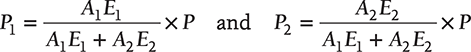
where A1 and A2 are cross-section of tube and rod, respectively; E1 and E2 are modulus of elasticity of tube and rod materials, respectively.
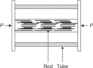
FIGURE 12.12
Compound Bar
On solving Equations (12.1) and (12.2), we get
12.7 STRESS AND STRAIN IN AN ASSEMBLY OF TUBE AND BOLT
Figure 12.13 shows stress and strain produced in a compound rod.
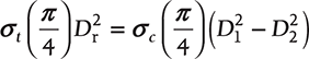

FIGURE 12.13
An Assembly of Tube and Bolt
where r subscript is used for rod. Rod is subjected to tensile stress and tube is subjected to compressive stress.
The reduction in length of tube and extension in rod may be different due to difference in materials of tube and rod.
EXAMPLE 12.7
A steel rod of 20 mm diameter passes centrally through a steel tube of internal and external diameters of 25 mm and 30 mm, respectively. The tube is 800 mm long and is closed by rigid washers of negligible thickness which is fastened by nuts threaded on the rod. The assembly diagram is shown in Figure 12.14.

- The nuts are tightened until the compressive load on the tube reaches 25 kN, calculate the stress on the tube and the rod.
- Find the increase in these stresses when one nut is tightened by one-quarter of a turn relative to the other. There are 5 threads per 10 mm. Take E = 200 kN/mm2.
SOLUTION
When the nut is tightened, there will be a compressive load on the tube which will be equal to the tensile load on the rod. Compressive stress cannot be equal to tensile stress because it depends on cross section area and strength of the material.
Pr = Pt = P, where Pr and Pt are loads on rod and tube, respectively.
σrAr = σtAt, where σr and σt are tensile stress on rod and compressive stress on tube, respectively; and Ar and At are the cross-sectional areas of the rod and tube, respectively.

- Compressive stress on tube,

Tensile stress on rod, σr = 0.6875 σt = 0.6875 × 115.74 N/m2 = 79.57 N/mm2
- Let σr1 and σt1 be the stress due to tightening of nut by one quarter of a turn.
σr1 = 0.6875 σt1
Reduction in the length of the tube 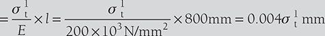
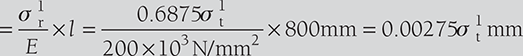
But, contraction in the tube + Extension in the rod = Axial movement of the nut ![]()
EXAMPLE 12.8
In example 12.7, the nut is removed and tube and rod are welded to washers and a compressive load of 25 kN is applied on washers as shown in the given Figure:
Find the stresses in tube and rod.
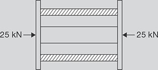
FIGURE 12.15
Fixed End of Tube and Rod Assembly
SOLUTION
In this case change in length in tube and rod will be same as shown in Figure 12.15.
i.e., δlt = δlr
or, 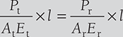
or, 
or, 
and also ![]()
On solving Equations (12.3) and (12.4), we get
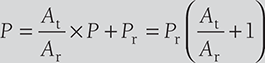
or, 
Stress in rod, 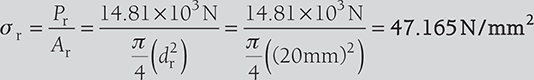
EXAMPLE 12.9
A solid steel bar 0.5 m long and 0.07 m in diameter, is placed inside an aluminum tube having 0.075 m inside diameter and 0.10 m outside diameter. The steel bar is 0.15 mm longer than the aluminum tube. An axial load of 600 MN is applied to the bar and cylinder through rigid cover plate as shown in Figure 12.16:

FIGURE 12.16
Steel Bar and Aluminum Tube Assembly
Find the stress developed in steel bar and cylinder through the rigid cover plate.
SOLUTION
Cross-sectional area of tube, 
Cross-sectional area of steel rod, 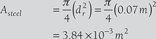
Let compression in tube is δlAl m.
Therefore, the compression in steel bar, δlsteel = δlAl + (0.15 × 10⁻³m )

Strain in steel bar, 
Stress in tube, 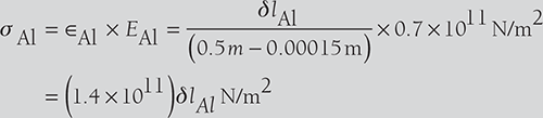
Stress in bar, 
Total load on assembly = Load on tube + Load on steel bar = δAl × AAl + δsteel × Asteel
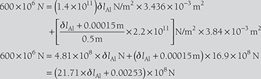
or, ![]()
Hence, stress in tube, 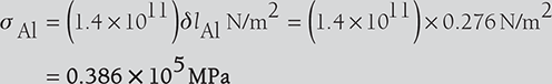
stress in bar, 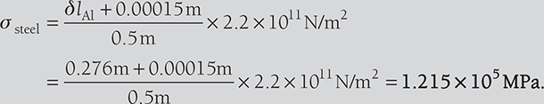
EXAMPLE 12.10
A concrete column of 37.5 cm2 cross-section, reinforced with steel rods having a total cross-sectional area 7.5 cm2 carries a load of 800 kN as shown in Figure 12.17:
If E for steel is 15 times greater than that of concrete, calculate the stresses produced in steel and concrete.
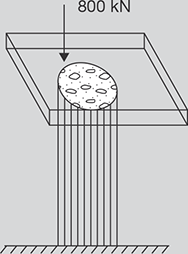
FIGURE 12.17
Concrete Column
Contraction in both the steel and concrete will be same.
and load, ![]()
Since, ∈steel = ∈concrete

or, 
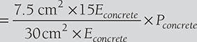
or, Psteel = 3.75Pconcrete
From Equation (12.5),
![]() σconcrete = Pconcrete / Aconcrete = 56.14 MN/m2
σconcrete = Pconcrete / Aconcrete = 56.14 MN/m2
Psteel = 800 kN − 168.42 kN = 631.5 σsteel = Psteel / Asteel = 842.106 MN/m2
12.8 STRESS AND STRAIN IN COMPOSITE BAR
Any tensile or compressive member which consists of two or more bars in series, usually of different materials, is called composite bars (Figure 12.18). In this case, Load on both the rods will be same but strain produced will be different.

FIGURE 12.18
Composite Bar
Total strain 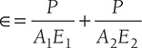
where A1, E1 ∈1 are cross-section area, modulus of elasticity, and strain produced in material 1.
Similarly, A2, E2, ∈2 are cross-section area, modulus of elasticity, and strain produced in material 2.
12.9 TEMPERATURE STRESS
If the temperature of a material is increased, there will be expansion in the material (except ice) and if the temperature is decreased, there will be a contraction in the material. If these expansion and contraction occur freely there will be no stress in the material and if this expansion or contraction is prevented then stress will be set up in the material, which is known as the temperature of thermal stress.
where δl is change in length; l0 is original length; δ is coefficient of linear expansion; and Δt is change in temperature.
EXAMPLE 12.11
A composite bar consisting of aluminum and steel components as shown in Figure 12.19, is connected to two grips at the ends at a temperature of 100°C. Find the stress in the two rods when the temperature falls to 60°C (i) If ends do not yields, and (ii) if ends yield by 0.5 mm. Assume Esteel = 2 × 10⁵ MPa, EAl = 0.7 × 10⁵ MPa, αsteel = 1.17 × 10⁻⁵ per degree centigrade, αAl = 2.34 × 10⁻⁵ per degree centigrade. Cross-sectional areas of aluminum and steel bars are 400 and 250 mm2, respectively.
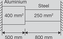
FIGURE 12.19
Compositer Bars with Fixed Ends
SOLUTION
There is a contraction in the bars due to a decrease in temperature.If contraction is free to change in length,
Δl = lAl × αAl × Δt + lst × αst × Δt = (lAl × αAl + lst × αst) × Δt
= (0.5m × 2.34 × 10−5 per °C + 0.8 m × 1.17 × 10−5 per °C )(100°C − 60°C )
= 0.8424 mm.
When contraction is prevented tensile stresses are produced inthe rod.
Loads in two rods will be same.
Case I: When ends do not yeild.
Total contraction = Contraction in aluminum + Contraction in steel

or, σst = 0.099 × 10⁹N/m2 = 99.5MPa
σAl = 0.625σst = 62.2MPa
Case II: When the ends yeild by 0.5 mm.
Contraction prevented = 0.8424 − 0.5 = 0.3424 mm
or, σst = 40.45MPa
σAl = 25.28MPa
12.10 STRESS AND STRAIN DUE TO SUDDENLY APPLIED LOAD
Suppose W is a load suddenly applied on the collar of a rod and extension due to the load application is δl as shown in Figure 12.20 (a). The original length of the rod is λ. The work done by the load W is U = W × δl.

FIGURE 12.20
(a) Suddenly Applied Load W on a Rod and (b) Load and Deflection Graph for Equivalent Gradually Applied Load
Now consider the equivalent weight for same work is P which is applied gradually. Work done by gradually applied load P (Figure 12.20 (b)),
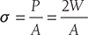
Thus, P = 2W
Hence, grdually applied load for same work done is equal to two times of suddenly applied load.
Stress produced, ![]() and strain,
and strain, 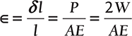
12.11 STRESS AND STRAIN FOR IMPACT LOAD
Impact load is a load which is applied to a body with some velocity as shown in Figure 12.21. Suppose a load W released from a height h on a collar of a rod of length l and change in length due to impact loading is δl. Now, work done by impact load W is

FIGURE 12.21
Impact Loading on a Rod
Suppose the equivalent load for same work done is P.
Now, work done by equivalent gradual load P
Thus, ![]() where
where ![]()
or, ![]()
or, 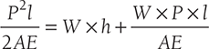
or, P2l − 2WPl − 2WhAE = 0
or, 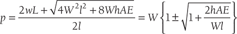

Here, –ve sign is neglected since we are interested to find the maximum stress
EXAMPLE 12.12
A steel rod of 10 mm diameter and of 5 m length has a collar as shown in Figure 12.22:
Find the instantaneous stress and strain when a pull of 200 kN: (i) is gradually applied, (ii) is suddenly applied, and (iii) falls centrally from a height of 120 mm on the collar. E = 200 GN/m2

FIGURE 12.22
A Steel Rod with Collar
SOLUTION
- For gradually applied load

- For suddenly applied load
- For impact loading

12.12 RELATION BETWEEN STRESS AND VOLUMETRIC STRAIN
12.13 RELATION BETWEEN MODULUS OF ELASTICITY AND BULK MODULUS
Suppose a block is subjected by three-dimensional forces P as shown in Figure 12.23.
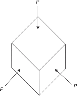
FIGURE 12.23
Fluid Pressure and Volumetric Strain of a Cube
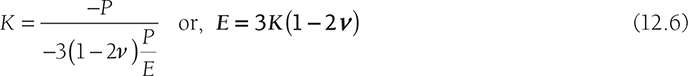
Bulk modulus is a ratio of fluid pressure and volumetric strain. It is denoted by K.

Here –ve sign is used for reduction in volume.
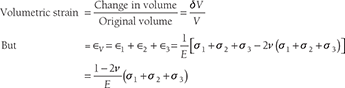
Let us consider a cube of unit length is subjected to fluid pressure P. It is clear that the principal stresses are –P, –P, and –P and linear strain in each direction is
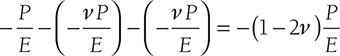
Volumetric strain = sum of linear strains ![]()
Hence,
12.14 RELATION BETWEEN MODULUS OF ELASTICITY AND MODULUS OF RIGIDITY
Modulus of rigidity (G) is the ratio of shear stress (τ) and shear strain (ϒ).
Let us consider an elemental cube ABCD be subjected to a simple shear stress τxy as shown in Figure 12.24 (a). An equivalent system with principal stresses τxy and −τxy are acting along the diagonals as shown in Figure 12.24 (b). The distorted condition of the cube is shown in Figure 12.24 (c).

Draw C1M perpendicularto AC and join AC1
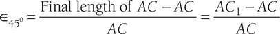
Also, AC1 = AM (since γ is small)

But, CC1 = γ × BC and AC = ![]()

Now, ∈45° can also be found by referring to the equivalent system of Figure 12.24 (b) as:
where σ1 = +τxy and σ2 = −τxy
From Equation (12.7)
From Equation (12.6) in previous section and Equation (12.8)
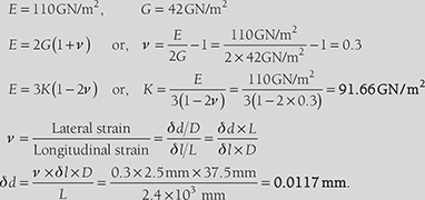
EXAMPLE 12.13
A bar of 50 mm diameter is subjected to a load of 100 kN. The measured extension on the gauge length of 250 mm is 0.12 mm and the change in diameter is 0.0040 mm. Calculate Poisson’s ratio, volumetric strain, and value of three moduli of elasticity.
SOLUTION
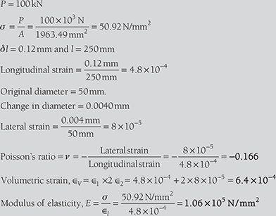
E = 2G(1 + v )
= 2G (1 + 0.166) or, G = 45.490 kN/mm2
E = 3K(1 − 2v ) ⇒ 1.06 × 10⁵ N/mm2 = 3K(1 − 2 × 0.166)
K = 52.935 kN/mm2
EXAMPLE 12.14
EXAMPLE 12.15
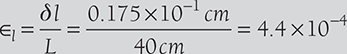
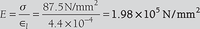
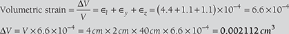
A bar 2 cm × 4 cm in cross section and 40 cm long is subjected to an axial tensile load of 70 kN as show in Figure 12.25. It is found that the length increases by 0.175 mm and a lateral dimension of 4 cm decreases by 0.0044 mm. Find: (i) Young’s modulus, (ii) passion’s ratio, (iii) change in volume of the bar, and (iv) bulk modulus.
SOLUTION
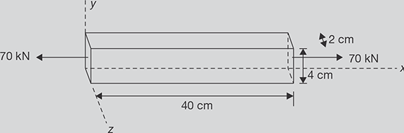
FIGURE 12.25
A Rod Under Tensile Load
Cross-sectional area of bar = 2 × 4 = 8 cm2

RECAP ZONE
Points to Remember
- The stress developed in the material is perpendicular to the cross-section, it is known as direct stress and if it is tangential or parallel to the cross-section, it is known as shear stress.
- If the stress distribution along the cross-section is uniform, it is known as simple or normal stress. σ = P/A.
- The ratio of lateral to longitudinal strain is constant which is known as Poisson’s ratio (ⱱ).
- Volumetric strain,
 Superficial strain,
  where ΔV is the change in volume, V is the original volume, ΔA is a change in the area, and A is the original area.
 - Hook’s law states that stress and strain are perpendicular to each other under the elastic limit.
- The elastic deformation portion of the stress-strain diagram is generally represented as a linear relationship between stress and strain.
- The elastic limit is the limit beyond which the material will no longer go back to its original shape when the load is removed.
- Yield point is the point at which the material will have an appreciable elongation or yielding without any increase in load.
- The maximum ordinate in the stress-strain diagram is the ultimate strength or tensile strength. Necking starts from this point.
- Rapture strength is the strength of the material at rupture point. This is also known as the breaking strength.
- Modulus of resilience is the work done on a unit volume of material as the force is gradually increased from zero to elastic limit.
- Modulus of toughness is the work done on a unit volume of material as the force is gradually increased from zero to rupture point.
- Working stress is defined as the actual stress of a material under a given loading. The maximum safe stress that a material can carry is termed as the allowable stress.
- The allowable stress should be limited to values not exceeding the proportional limit.
- The ratio of this strength (ultimate or yield strength) to allowable strength is called the factor of safety.
- If the temperature of a material is increased, there will be expansion in the material (except ice) and if the temperature is decreased, there will be a contraction in the material. If these expansion and contraction occur freely there will be no stress in the material and if this expansion or contraction is prevented then stress will be set-up in the material, which is known as the temperature of thermal stress.
- The principal stress is the maximum or minimum normal stress in a plane, which is subjected to multidimensional stress, and this plane is known as the principal plane along which shear stress is zero.
Important Formulae
- Poisson ratio:
- Modulus of elasticity:

- Gauge length in the tensile test: Lgauge = 5.65

- Change in length in a stepped bar: Change in length,
- Total extension in varying tapered bar,

- In compound bars, the extensions or compressions are same in each rod.
- In composite rods, the stress will be same on each rod.
- Thermal stress = Eα Δt
- In suddenly applied load: Stress produced,
 and strain,
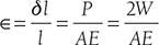
- In impact loading

- Volumetric stain and stress
- E = 3K (1 − 2ν )
-

- Resultant stress in the direction
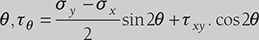
- For Principal Stresses,
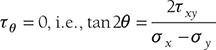
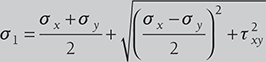
- Principal stresses:

-

-
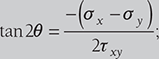 condition for maximum shear stress
REVIEW ZONE
Multiple-choice Questions
- Hook’s law holds good up to:
- Yield point
- Proportional limit
- Plastic limit
- Ultimate point
- Strain is the ratio of:
- Change in volume to original volume
- Change in length to original length
- Change in cross-section area to original cross-section area
- All of the above
- Deformation per unit length is known as:
- Linear strain
- Lateral strain
- Volumetric strain
- None of these
- Modulus of rigidity is defined as the ratio of:
- Longitudinal stress and longitudinal strain
- Lateral stress and lateral strain
- Shear stress and shear strain
- Any one of the above
- Tensile strength of a material is obtained by dividing the maximum load during the test by the:
- Area at the time of fracture
- Original cross-section area
- Average of (a) and (b)
- Minimum area after fracture
- For steel, the ultimate shear strength in shear in comparison to tension is nearly:
- Same
- Half
- One-third
- Two-third
- In tensile test of steel, the breaking stress as compared to ultimate stress is:
- Less
- More
- Same
- None of these
- The value of modulus of elasticity for mild steel is of the order of:
- 2.1 × 10⁵ kg/cm2
- 2.1 × 10⁶ kg/cm2
- 2.1 × 10⁷ kg/cm2
- 2.1 × 10⁸ kg/cm2
- The value of Poisson ratio for steel lies between:
- 0.01–0.1
- 0.23–0.27
- 0.25–0.33
- 0.4–0.6
- The property by which a material returns to its original shape after removal of external load is known as:
- Elasticity
- Plasticity
- Ductility
- Malleability
- The materials which exhibit the same elastic properties in all directions are known as:
- Homogeneous
- Isotropic
- Isentropic
- Inelastic
- The properties of a material which allows it to be drawn into a smaller section is called:
- Elasticity
- Plasticity
- Ductility
- Malleability
- Poisson ratio is defined as:
- Longitudinal stress/longitudinal strain
- Longitudinal stress/lateral stress
- Lateral strain/longitudinal strain
- Lateral stress/lateral strain
- The property of material by which it can be rolled into a sheet is known as:
- Elasticity
- Plasticity
- Ductility
- Malleability
- In tensile test of mild steel, necking starts from:
- Proportional limit
- Plastic limit
- Ultimate point
- Rupture point
- The strain energy stored in a body, when it is strained up to elastic limit is known as:
- Resilience
- Proof resilience
- Modulus of resilience
- Toughness
- The maximum strain energy stored in a body is known as:
- Resilience
- Proof resilience
- Modulus of resilience
- Toughness
- Proof resilience per unit volume is known as:
- Resilience
- Proof resilience
- Modulus of resilience
- Toughness
- The deformation of a bar under its own weight compared to the deformation of the same body subjected to a direct load equal to weight of the body is:
- Same
- Half
- Double
- One-fourth
- The tensile stress in a conical rod, having diameter D at bottom, d at top, length l and subjected to tensile force F, at distance x from small end will be:
-

Answers
- b
- d
- a
- c
- b
- b
- a
- b
- c
- d
- b
- c
- c
- d
- c
- a
- b
- b
- b
- c
Theory Questions
- Define stress and strain.
- What do you mean by normal stress and shear stress?
- Define longitudinal and lateral strains.
- Define linear, superficial and volumetric strain.
- Define: Young modulus, elastic limit, proportional limit, yield point, ultimate point, breaking point, modulus of rigidity, bulk modulus, and Poisson’s ratio.
- Differential engineering strain and true strain.
- State Kook’s law.
- Establish relationship between E and K.
- Establish relationship between E and G.
- Establish relationship between E, K and G.
- Differentiate compound bar and composite bar.
- Write note on gradual loading, suddenly applied loading, and impact loading.
Numerical Problems
- What is the greatest length of a metal wire that can be hung vertically under its own weight? If the allowable stress in the metal of wire is 3 MPa and density of metal is 12 × 103 kg/m3.
- A steel punch can apply maximum compressive load 1000 kN. Find the minimum diameter of the hole, which can be punched through a 10 mm thick steel plate. Assume ultimate shearing strength of steel plate is 350 N/mm2.
- A circular rod is tapered from one end to other end; the diameter at one end is 2 cm and the diameter at the other end is 1 cm. Its length is 20 cm long. On applying an axial load of 6 kN, it was found to extend by 0.068 mm. Find the modulus of elasticity of the material of the rod.
- (a) A uniform bar of length L, cross-sectional area A, and unit mass ρ is suspended vertically from one end. Show that its total elongation is d = ρgL2/2E.
(b) In the part (a), if the cross-sectional area, A = 300 mm2 and length = 150 m and tensile load applied id 20 kN at the lower end, unit mass of the rod = 7850 kg/m3 and E = 200 Gpa. Find the total elongation of the rod.
- A steel rod of 25 mm diameter is placed concentrically in a copper tube of an internal diameter 38.5 mm and external diameter of 41.5 mm. Nuts and washers are fitted on the rod so that the ends of the tube is enclosed by the washers. The nuts are initially tightened to give a compressive stress of 30 N/mm2 on the tube and a tensile load of 45 kN is then applied on the rod. Find the resultant stresses in the tie rod and tube, Es = 205GPa, Ec = 80GPa.