
CHAPTER 8
Refrigeration and Air Conditioning
Learning Objectives
By the end of this chapter, the student will be able:
- To understand the basic concepts of refrigeration and air conditioning
- To describe the different types of refrigeration cycles
- To demonstrate the structure and working of a household refrigerator
- To understand the properties of air-vapour mixture
- To differentiate the working of the window and split air conditioners
8.1 INTRODUCTION
Initially, the main purpose of refrigeration was to conserve foods. The Chinese were the first to find out that ice increased the life and improved the taste of drinks and for centuries Eskimos have conserved food by freezing it. At the beginning of the 19th century, it had been observed that the growth of microorganisms is temperature-dependent, that growth declines as temperature falls, and that growth becomes very slow at temperatures below +10°C. As a consequence of this knowledge, it was now possible to use refrigeration to conserve food-stuffs and natural ice came into use for this purpose.
The idea of air conditioning started before a machine was created to produce the cooling effect desired. The first attempt at building an air conditioner was made by Dr. John Gorrie (1803–1855), an American physician, in Apalachicola, Florida. During his practice there in the 1830s, Dr. Gorrie creating an ice-making machine that essentially blew air over a bucket of ice for cooling hospital rooms of patients suffering from malaria and yellow fever.
8.2 REFRIGERATOR AND HEAT PUMP
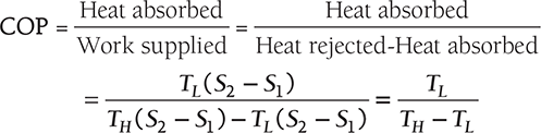
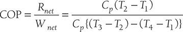
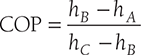
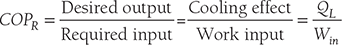
Clausius, statement of the Second Law of Thermodynamics: It is impossible to construct a device that, operating in a cycle, has no effect other than the transfer of heat from a cooler to a hotter body. Thus, the Clausius statement tells us that heat will not flow from cold to hot regions without the assistance of outside agents. The devices that provide this assistance are called refrigerators and heat pumps. The working of refrigeration and heat pump is shown in Figure 8.1. The distinction between refrigerator and heat pump is one of purpose more than technique. The refrigeration unit transfers heat from cold to hot regions for the purpose of cooling the cold region while the heat pump does the same thing with the intent of heating the hot region. The performance of the refrigerators and the heat pump is expressed in terms of the Coefficient of Performance (COP), which is defined as:


FIGURE 8.1
Working of Refrigeration and Heat Pump
Tones of Refrigeration (TR): the cooling effect produced is quantified as tons of refrigeration, also referred to as “chiller tonnage”.
Where Q - mass flow rate of coolant in kg/h
Cp - coolant specific heat in kCal/kg °C
Ti - inlet temperature of coolant to the evaporator (chiller) in °C
To - outlet temperature of coolant from the evaporator (chiller) in °C.
1 TR of refrigeration = 3,024 kCal/h heat rejected Power of unit of refrigerator = QL/COP
Capacity of refrigeration plant = Heat removal rate in tones.
8.3 COMPONENTS OF REFRIGERATION SYSTEM
There are five basic components of a refrigeration system, these are:
- Evaporator
- Compressor
- Condenser
- Expansion valve
- Refrigerant; to conduct the heat from the product in order for the refrigeration cycle to operate successfully each component must be present within the refrigeration system.
8.3.1 Evaporator
The purpose of the evaporator is to remove unwanted heat from the product, via the liquid refrigerant. The liquid refrigerant contained within the evaporator is boiling at a low-pressure. The level of this pressure is determined by two factors:
- The rate at which the heat is absorbed from the product to the liquid refrigerant in the evaporator.
- The rate at which the low-pressure vapor is removed from the evaporator by the compressor to enable the transfer of heat, the temperature of the liquid refrigerant must be lower than the temperature of the product being cooled. Once transferred, the liquid refrigerant is drawn from the evaporator by the compressor via the suction line. When leaving the evaporator coil the liquid refrigerant is in vapor form.
8.3.2 Compressor
The purpose of the compressor is to draw the low-temperature, low-pressure vapor from the evaporator via the suction line. Once drawn, the vapor is compressed. When vapor is compressed it rises in temperature. Therefore, the compressor transforms the vapor from a low-temperature vapor to a high-temperature vapor, in turn increasing the pressure. The vapor is then released from the compressor into the discharge line.
8.3.3 Condenser
The purpose of the condenser is to extract heat from the refrigerant to the outside air. The condenser is usually installed on the reinforced roof of the building, which enables the transfer of heat. Fans mounted above the condenser unit are used to draw air through the condenser coils. The temperature of the high-pressure vapor determines the temperature at which the condensation begins. As heat has to flow from the condenser to the air, the condensation temperature must be higher than that of the air; usually between -12°C and -1°C. The high-pressure vapor within the condenser is then cooled to the point where it becomes a liquid refrigerant once more, whilst retaining some heat. The liquid refrigerant then flows from the condenser in to the liquid line.
8.3.4 Expansion Valve
Within the refrigeration system, the expansion valve is located at the end of the liquid line, before the evaporator. The high-pressure liquid reaches the expansion valve, having come from the condenser. The valve then reduces the pressure of the refrigerant as it passes through the orifice, which is located inside the valve. On reducing the pressure, the temperature of the refrigerant also decreases to a level below the surrounding air. This low-pressure, low-temperature liquid is then pumped in to the evaporator.
8.4 TYPES OF REFRIGERATION SYSTEMS
Broadly, the refrigeration systems can be categorized as:
- Air-refrigeration system
- Vapor compression refrigeration system
- Absorption refrigeration system
8.4.1 Air-refrigeration System
Reversed Carnot Cycle
Reversed Carnot cycle is shown in Figure 8.2. It consists of the following processes. Process a-b: Absorption of heat by the working fluid from the refrigerator at constant low-temperature TL during isothermal expansion.
Process b-c: Isentropic compression of the working fluid with the aid of external work. The temperature of the fluid rises from TL to TH.
Process c-d: Isothermal compression of the working fluid during which heat is rejected at constant high-temperature TH.
Process d-a: Isentropic expansion of the working fluid. The temperature of the working fluid falls from TH to TL.
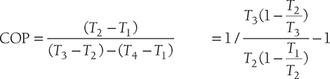
COP of Refrigerator:
Practical use of the reversed Carnot cycle is not possible for refrigeration purpose as the isentropic process requires a very high-speed operation, whereas the isothermal process requires a very low-speed operation.
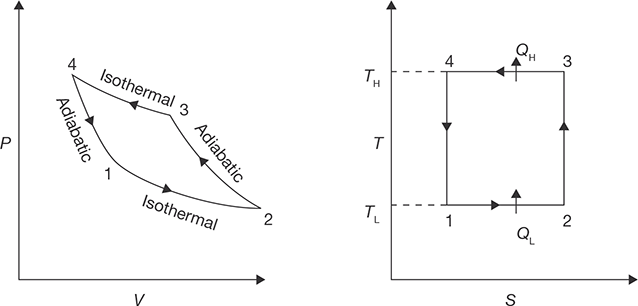
FIGURE 8.2
P-V and T-S Diagrams for Reversed Carnot Cycle
Bell–Coleman Cycle or Reversed Brayton Cycle
In this system, air is taken into the compressor from the atmosphere and compressed then the hot compressed air is cooled in heat exchanger up to the atmospheric temperature. The cooled air is then expanded in an expander. The temperature of the air coming out from the expander is below the atmospheric temperature due to isentropic expansion. The low-temperature air coming out from the expander enters into the evaporator and absorbs the heat. The cycle is repeated again and again. The working of Reversed Brayton Cycle is represented on P-V and T-S diagrams in Figure 8.3.
Process 1-2: Suction of air into the compressor.
Process 2-3: Isentropic compression of air by the compressor.
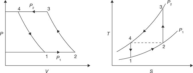
Process 3-4: Discharge of high-pressure air from the compressor into the heat exchanger (The reduction in the volume of air from V3 to V4 is due to the cooling of air in the heat exchanger.)
Process 4-1: Isentropic expansion of air in the expander.
Process 1-2: Absorption of heat from the evaporator at constant pressure and suction of air into the compressor.
Work done per kg of air for the isentropic compression process 2-3 is given by:
Work developed per kg of air for the isentropic expansion process 4-1 is given by:
Net refrigerating effect per kg of air is given by:
For perfect inter-cooling, the required condition is T4 = T2
For isentropic compression process 2-3 and for expansion process 5-6, we have,

Advantages and Disadvantages of Air-refrigeration System
Advantages
- Air is a cheaper refrigerant and available easily compared to other refrigerants. There is no danger of fire or toxic effects due to leakage.
- The total weight of the system per ton of refrigerating capacity is less.
Disadvantages:
- The quantity of air required per ton refrigerating capacity is far greater than other systems. The COP is low and hence maintenance cost is high. The danger of frosting at the expander valves is more as the air taken into the system always contains moisture.
EXAMPLE 8.1
Carnot refrigeration cycle absorbs heat at 250 K and rejects heat at 300 K.
- Calculate the coefficient of performance of this refrigeration cycle.
- If the cycle is absorbing 1,050 kJ/min at 250 K, how many kJ of work is required per second.
- If the Carnot heat pump operates between the same temperatures as the above refrigeration cycle, what is the coefficient of performance?
- How many kJ/min will the heat pump deliver at 300 K if it absorbs 1,050 kJ/min at 250 K.
SOLUTION
Given: T1 = 250 K; T2 = 300 K
- Coefficient of performance of Carnot refrigeration cycle We know that coefficient of performance of Carnot refrigeration cycle,
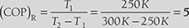
- Work required per second
Let WR = Work required per second
Heat absorbed at 250 K (i.e., T1), Q1 = l050 kJ/min = 17.5 kJ/s
We know that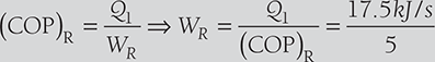 WR = 3.5 kJ/s
 - Coefficient of performance of Carnot heat pump
We know that coefficient of performance of a Carnot heat pump,

- Heat delivered by heat pump at 300 K
Let Q2 = Heat delivered by heat pump at 300 K.
Heat absorbed at 250 K (i.e., T1),
Q1 = 1050 kJ/min (Given)

EXAMPLE 8.2
The capacity of a refrigerator is 150 TR when working between – 5°C and 20°C. Determine the mass of ice produced per day from water at 20°C. Also, find the power required to drive the unit. Assume that the cycle operates on reversed Carnot cycle and latent heat of ice is 336 kJ/kg.
SOLUTION
Given: Q = 150 TR; T1 = –5°C = –5°C + 273 = 268 K; T2 = 20°C = 20 + 273 = 293 K
Mass of ice produced per day
Heat extraction capacity of the refrigerator = 150 TR × 210 kJ/min = 31,500 kJ/min
Heat removed from 1 kg of water at 20°C to form ice at 0°C (ITR = 210 kJ/min)
Mass of ice produced per min = 31,500 kJ/min/419.6 kJ/kg = 75.07 kg/min.
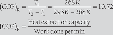
Work done per min. ![]()
Power required to drive the unit ![]()
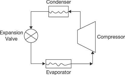
8.4.2 Vapour Compression Refrigeration System
A simple vapor compression refrigeration system consists of the following equipments (Figure 8.4):
- Compressor,
- Condenser,
- Expansion valve,
- Evaporator.
The low-temperature and low-pressure vapor is compressed by a compressor to high-temperature and high-pressure vapor. This vapor is then condensed into condenser at constant pressure and then passes through the expansion valve. Here, the vapor is throttled down to a low-pressure liquid and passed through an evaporator, where it absorbs heat from the surroundings and vaporizes into low-pressure vapor. The cycle then repeats again and again. The heat and work interaction in vapor compression process takes place in following way:
- Compressor requires work (W). The work is supplied to the system.
- During condensation, heat QH the equivalent of latent heat of condensation, etc, is removed from the refrigerant.
- During evaporation, heat QL equivalent to the latent heat of vaporization is absorbed by the refrigerant.
- There is no exchange of heat during throttling process through the expansion valve as this process occurs at constant enthalpy.
Figure 8.5 shows a simple vapor compression refrigeration cycle on T–S diagram for different compression processes. The cycle works between temperatures T1 and T2 representing the condenser and evaporator temperatures, respectively. The thermodynamic process of the cycle A–B–C–D is given as:
- Process B–C: Isentropic compression of the vapor from state B to C.
- Process C–D: Heat rejection in condenser is at constant pressure.
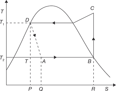
FIGURE 8.5
T-S Diagram of Vapor Compression Refrigeration Cycle - Process D–A: An irreversible adiabatic expansion of vapor through the expansion value. The pressure and temperature of the liquid are reduced. The process is accompanied by partial evaporation of some liquid. The process is shown by dotted line.
- Process A–B: Heat absorption in the evaporator at constant pressure. The final state depends on the quantity of heat absorbed and same may be wet, dry or superheated.
COP of Vapor Compression Cycle:
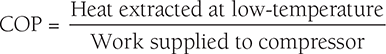
Heat extracted from the system (i.e., absorbed in absorber) = Heat transfer during the process, A–B = refrigerating effect.
Work of compression, W = hC − hB
Heat rejected from condenser,
Factors Affecting the Performance of Vapour Compression Refrigeration System
- Sub-cooling: By passing the liquid refrigerant from the condenser through a heat exchanger through, which the cold vapor at suction from the evaporator is allowed to flow in the reversed direction. This process sub-cools the liquid but superheats the vapor. Thus, COP is not improved though refrigeration effect is increased. But, by making use of enough quantity of cooling water so that the liquid refrigerant is further cooled below the temperature of saturation. In some cases, a separate sub cooler is also made use of for this purpose. In this case, COP is improved.
- Superheating of Vapor: If the vapor at the compressor entry is in the superheated state, which is produced due to higher heat absorption in the evaporator, then the refrigerating effect is increased. However, COP may increase, decrease or remain unchanged depending upon the range of pressure of the cycle.
- Change in Suction Pressure: The decrease in suction pressure decreases the refrigeration effect and at the same time increases the work of compression. But, both the effects tend to decrease the COP.
- Change in Discharge Pressure: The increase in discharge pressure results in lower COP. Hence, the discharge pressure should be kept as low as possible depending upon the temperature of the cooling medium available.
- Effect of Volumetric Efficiency of Compressor: The factors like clearance volume, pressure drop through discharge and suction valves, leakage of vapor along the piston and superheating of cold vapor due to contact with hot cylinder walls, affects the volume of the vapor actually pumped by the compressor. The volumetric efficiency of a compressor is defined as;

The actual amount of vapor sucked during the suction stroke is (V1 – V2) while the stroke volume is (V1 – VC). Volumetric efficiency decreases the refrigeration effect.
Comparison between Vapour Compression Cycle and Reversed Carnot Cycle
- Vapor compression cycle requires more compression work than the Reversed Carnot cycle.
- No work is done during the throttling process in Vapor compression cycle but work is done in expansion process in Reversed Carnot cycle.
- In vapor compression expansion process is irreversible whereas in Reversed Carnot cycle it is reversible.
Advantages and Disadvantages of Vapour Refrigeration Systems over Air-refrigeration Systems
Advantages
- Vapor refrigeration system has higher COP than the Air refrigeration system.
- Vapor refrigeration system has easer controllable expansion process.
- It has low running cost.
- It requires smaller evaporator.
Disadvantages
- Vapor refrigeration system has higher capital cost.
- In Vapor refrigeration, system leakage problem may occur.
8.4.3 Absorption Refrigeration Cycle
The absorption cycle is a process by which refrigeration effect is produced through the use of two fluids and some quantity of heat input, rather than electrical input as in the more familiar vapor compression cycle. Both vapor compression and absorption refrigeration cycles accomplish the removal of heat through the evaporation of a refrigerant at a low pressure and the rejection of heat through the condensation of the refrigerant at a higher pressure. The method of creating the pressure difference and circulating the refrigerant is the primary difference between the two cycles. The vapor compression cycle employs a mechanical compressor to create the pressure differences necessary to circulate the refrigerant. In the absorption system, a secondary fluid or absorbent is used to circulate the refrigerant. Because the temperature requirements for the cycle fall into the low-to-moderate temperature range, and there is significant potential for electrical energy savings, absorption would seem to be a good prospect for the geothermal application.
Absorption machines are commercially available today in two basic configurations. For applications above 32° F (primarily air conditioning), the cycle uses lithium bromide as the absorbent and water as the refrigerant. For applications below 32° F, an ammonia/water cycle is employed with ammonia as the refrigerant and water as the absorbent.
8.5 TYPE OF REFRIGERANTS
Research on the use of refrigerant is continuously going on due to an adverse effect on depletion of ozone layer. The production of many refrigerants will soon end, including R-22 and R-123 in accordance to the requirements of the Montreal Protocol. Suppliers currently offer a range of refrigerants based on chiller type, capacity, and regulatory requirements. The refrigerants can be classified into following classes:
- HaloCarbons
Halocarbon Refrigerants are all synthetically produced and were developed as the Freon family of refrigerants. Some of the refrigerants in this class are given below:
CFC’s: R11, R12, R113, R114, R115
HCFC’s: R22, R123
HFC’s: R134a, R404a, R407C, R410a
- Inorganic Refrigerants
Following refrigerants are used as inorganic refrigerants:
Carbon Dioxide, Water, Ammonia, Air, Sulphur dioxide.
- Zeotropic Refrigerants: A stable mixture of two or several refrigerants whose vapor and liquid phases retain identical compositions over a wide range of temperatures.
- Hydrocarbon Refrigerants
Following hydrocarbon gases have been used as refrigerants in industrial, commercial and domestic applications:
R170, Ethane (C2H6)
R290 , Propane (C3H3)
R600, Butane (C4H10)
R600a, Isobutane (C4H10)
Blends of the above Gases.
8.6 DOMESTIC REFRIGERATOR
Domestic or household refrigerator is an appliance used for the short term preservation of food products by means of refrigeration. A domestic refrigerator is a metal cabinet with a built-in hermetically sealed refrigerating unit. Inside the cabinet is a cold chamber with shelves for storing products. Heat insulation is placed between the walls of the cold chamber and the case of the refrigerator. The air in the cold chamber is cooled by means of heat transfer between the air and the cold surface of the evaporator. Domestic refrigerators have a storage space of 20 to 800 L. The domestic refrigerator may be of compression type or absorption type, but on these days most of the domestic refrigerators are of compression type. The major parts of the refrigerator that carry out actual working of the refrigerator are discussed in Figure 8.6:
Refrigerant: The refrigerant flows through all the internal parts of the refrigerator. It absorbs the heat from the substance to be cooled in the evaporator (chiller or freezer) and throws it to the atmosphere via the condenser. The refrigerant keeps on circulating through all the internal parts of the refrigerator in a cycle.
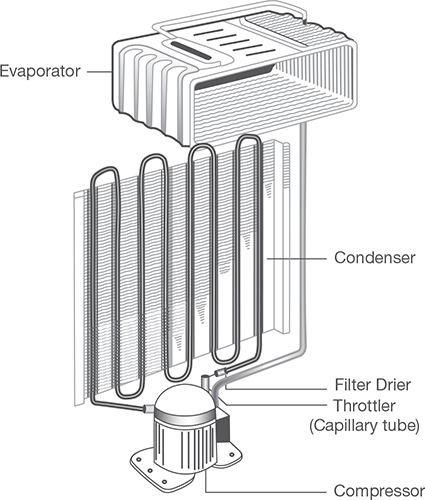
Compressor: The compressor is located on the back side and in the bottom of the refrigerator. The compressor draws the refrigerant from the evaporator and discharges it at high pressure and temperature. The compressor is driven by the electric motor and it is a major power consuming device of the refrigerator.
Condenser: The condenser is a thin coil of copper tubing located at the back of the refrigerator. The refrigerant from the compressor enters the condenser where it is cooled by the atmospheric air thus losing heat absorbed by it in the evaporator and the compressor.
Expansive valve or the capillary: The refrigerant leaving the condenser enters into the expansion device, which is the capillary tube in case of the domestic refrigerators. The capillary is the thin copper tubing made up of a number of turns of the copper coil. When the refrigerant is passed through the capillary its pressure and temperature drops down suddenly and then enters the evaporator.
Evaporator: Evaporator is a device, which is used to absorb the heat from the atmosphere by means of refrigerant, which gets evaporated. The evaporator is located in the atmosphere of substance, which is to be cooled or chilled. After evaporator, refrigerant again enters into the compressor.
8.7 PSYCHROMETRY
Psychrometry is the study of air-water vapor mixtures. It is also sometimes referred to as hygrometry. Many mechanical engineering devices exploit psychrometric processes, such as air conditioning systems and cooling towers. Two important principles upon which psychrometric relationships are based are the perfect gas equation and Dalton’s law regarding the mixture. The perfect gas equation, PV = RT, is a fundamental tool used to manipulate the characteristics as one sets out to analyze both definitions and various conditions. Since d = 1/v, another useful form of the equation is p = dRT.
Dalton’s Law of Partial Pressure: Dalton’s states that in a mixture of perfect gases, each constituent of the mixture behaves individually as the others are not present. This statement can be expressed as a series of mathematical relationships based on the following logic statements:
- The total pressure of the mixture is the sum of the individual or partial pressures of the constituents.
- The mass of the mixture is the sum of the masses of the individual constituents.
- The temperature of each constituent is equal to the temperature of the mixture.
- The volume of each of the constituents is equal to the volume of the mixture.
- The enthalpy of the mixture is the sum of the enthalpies of the individual constituents.
Total pressure of the air-water vapor mixture (pB) can be expressed by Dalton’s law equation as the sum of the partial pressures of the constituents; p = pa + pv and if the water vapor is saturated p = pa + pvs.
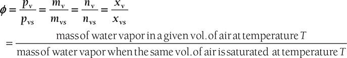
Relative Humidity (ϕ): It is defined as the ratio of partial pressure of water vapor in a mixture and saturated pressure of pure water at the same temperature T.
Humidity Ratio or Specific Humidity: The humidity (w) ratio is defined as the mass of water vapor per unit mass of dry air in the mixture of air and water vapor. This term can be 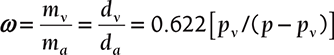 and if mixture is saturated ωS = 0.622 [pvs/( p − pvs )] as

Degree of Saturation (μ): It is the ratio of actual specific humidity and the saturated specific humidity, both at the same temperature T.

Dry Bulb Temperature (DBT): It is the temperature of the mixture as measured by a standard thermometer. The word ‘dry’ is used to imply that the sensor is exposed to the vapor mixture without any liquid present.
Wet Bulb Temperature (or Saturation Temperature, (WBT): It is the temperature at which water evaporating into moist air at a given dry-bulb temperature and humidity ratio can bring air to saturation adiabatically at the same pressure.
Specific Volume (v): It as commonly used, but with units of mixture volume per kilogram of the dry air.
Dew Point Temperature (DPT): It is the temperature of moist air saturated at the same pressure and humidity ratio as a given specimen of humid air. If we cool it further, water will start condensing and separates out as fog/dew.
8.8 PSYCHROMETRIC PROCESSES
8.8.1 Psychrometric Chart
A view of psychrometric chart is shown in Figure 8.7. The different psychrometric processes are shown in Figure 8.8.
Sensible Cooling
During this process, the moisture content of air remains constant but its temperature decreases as it passes over a cooling coil. To keep the moisture content constant, the surface of the cooling coil should be dry and its surface temperature should be greater than the dew point temperature of the air. If the cooling coil is 100% effective, then the exit temperature of the air will be equal to the coil temperature. However, in practice, the exit air temperature will be higher than the cooling coil temperature. Figure 8.9 shows the sensible cooling process 2–1 on a psychrometric chart. The heat rejection rate during this process is given by:
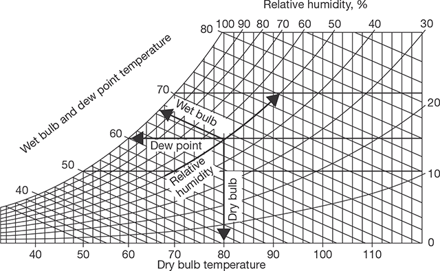
FIGURE 8.7
Psychrometric Chart
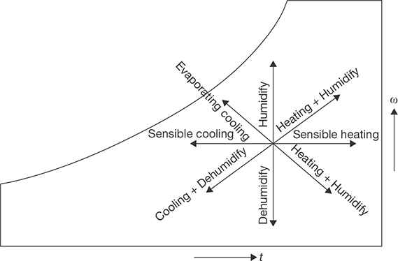

FIGURE 8.9
Sensible Cooling Process 2-1 on Psychrometric Chart
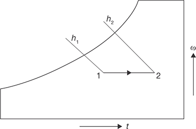
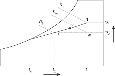
FIGURE 8.11
Cooling and Dehumidification Process
Sensible Heating
During this process, the moisture content of air remains constant and its temperature increases as it flows over a heating coil. The heat addition rate during this process is given by:
where cpm is the humid specific heat (≈1.0216 kJ/kg dry air) and ma is the mass flow rate of dry air (kg/s). Figure 8.10 shows the sensible heating process on a psychrometric chart.
Cooling and Dehumidification
When moist air is cooled below its dew-point by bringing it in contact with a cold surface, some of the water vapor in the air condenses and leaves the air stream as a liquid, as a result, both the temperature and humidity ratio of air decreases as shown. This is the process air undergoes in an air conditioning system. The actual process path depends on the type of cold surface, the surface temperature, and flow conditions, but for simplicity, the process line is assumed to be a straight line as shown in Figure 8.11. The heat and mass transfer rates can be expressed in terms of the initial and final conditions by applying the conservation of mass and conservation of energy equations as given below:
By applying mass balance for the water:
By applying energy balance:
From the above two equations, the load on the cooling coil, Qt is given by:
The 2nd term on the RHS of the above equation is normally small compared to the other terms, so it can be neglected. Hence,
It can be observed that the cooling and de-humidification process involves both latent and sensible heat transfer processes, hence, the total, latent and sensible heat transfer rates (Qr, Ql, and Qs) can be written as:
where Ql = ma (h1 − hw ) = ma.hfg (ω1 − ωw )
and Qs = ma (hw − h2 ) = ma.cpm (T1 − T2 )
Sensible Heat Factor (SHF)
It is defined as the ratio of sensible to total heat transfer rate (Qt), i.e.,
From the above equation, we can observe that an SHF of 1.0 corresponds to no latent heat transfer and an SHF of 0 corresponds to no sensible heat transfer. An SHF of 0.75 to 0.80 is quite common in air conditioning systems in a normal dry-climate. A lower value of SHF, say 0.6, implies a high latent heat load such as that occurs in a humid climate.
The temperature, Ts, is the effective surface temperature of the cooling coil and is known as apparatus dew-point (ADP) temperature. In an ideal situation, when all the air comes in perfect contact with the cooling coil surface, then the exit temperature of the air will be same as ADP of the coil. However, in the actual case, the exit temperature of the air will always be greater than the apparatus dew-point temperature due to boundary layer development as air flows over the cooling coil surface and also due to temperature variation along the fins, etc. Hence, we can define a by-pass factor (BPF) as it can be easily seen that higher the by-pass factor larger will be the difference between air outlet temperature and the cooling coil temperature. When BPF is 1.0, all the air bypasses the coil and there will not be any cooling or de-humidification.
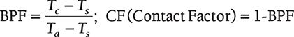
Where Tc temperature of air leaving, Ta is temperature of air entering and Ts is temperature of surface of cooling coil.
Heating and Humidification
During winter it is essential to heat and humidity the room air for comfort. As shown in Figure 8.11, this is normally done by first sensible heating the air and then adding water vapor to the air stream through steam nozzles as shown in Figure 8.12.
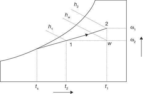
FIGURE 8.12
Heating and Humidification Process
Mass balance of water vapor for the control volume yields the rate, at which steam has to be added, i.e., mw:
where ma is the mass flow rate of dry air. From energy balance:
where Qh is the heat supplied through the heating coil and hw is the enthalpy of steam. Since this process also involves simultaneous heat and mass transfer, we can define a sensible heat factor for the process in a way similar to that of a cooling and dehumidification process.
Cooling and Humidification
As the name implies, during this process, the air temperature drops and its humidity increases. As shown in Figure 8.13, this can be achieved by spraying cool water in the air stream. The temperature of the water should be lower than the dry-bulb temperature of air but higher than its dew-point temperature to avoid condensation (TDPT < T2 < T1).

FIGURE 8.13
Cooling and Humidification Process
During this process, there is sensible heat transfer from air to water and latent heat transfer from water to air. Hence, the total heat transfer depends upon the water temperature. If the temperature of the water sprayed is equal to the wet-bulb temperature of the air, then the net transfer rate will be zero as the sensible heat transfer from air to water will be equal to latent heat transfer from water to air. If the water temperature is greater than WBT, then there will be a net heat transfer from water to air. If the water temperature is less than WBT, then the net heat transfer will be from air to water. Under a special case when the spray water is entirely recirculated and is neither heated nor cooled, the system is perfectly insulated and the make-up water is supplied at WBT, then at steady-state, the air undergoes an adiabatic saturation process, during which its WBT remains constant. This is the process of adiabatic saturation. The process of cooling and humidification is encountered in a wide variety of devices such as evaporative coolers, cooling towers, etc.
Heating and Dehumidification
This process can be achieved by using a hygroscopic material, which absorbs or adsorbs the water vapor from the moisture. If this process is thermally isolated, then the enthalpy of air remains constant, as a result, the temperature of air increases as its moisture content decreases as shown in Figure 8.14. This hygroscopic material can be a solid or a liquid. In general, the absorption of water by the hygroscopic material is an exothermic reaction, as a result heat is released during this process, which is transferred to air and the enthalpy of air increases.
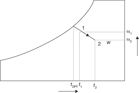
FIGURE 8.14
Heating Dehumidification Process
Mixing of Air Streams
Mixing of air streams at different states is commonly encountered in many processes, including in air conditioning. Depending upon the state of the individual streams, the mixing process can take place with or without condensation of moisture.
- Without condensation: Figure 8.15 shows an adiabatic mixing of two moist air streams during which no condensation of moisture takes place. When two air streams at state points 1 and 2 mix, the resulting mixture condition 3 can be obtained from mass and energy balance.

FIGURE 8.15
Mixing of Two Air Streams without CondensationFrom the mass balance of dry air and water vapor:
ma1ω1 + ma2ω2 = (ma1 + ma2 )ω3From energy balance:
ma1h1 + ma2h2 = (ma1 + ma2 )h3From the above equations, it can be observed that the final enthalpy and the humidity ratio of mixture are weighted averages of inlet enthalpies and humidity ratios. A generally valid approximation is that the final temperature of the mixture is the weighted average of the inlet temperatures. With this approximation, the point on the psychrometric chart representing the mixture lies on a straight line connecting the two inlet states. Hence, the ratio of distances on the line, i.e., (1-3)/(2-3) is equal to the ratio of flow rates ma2/ma1. The resulting error (due to the assumption that the humid specific heats being constant) is usu-ally less than 1%.
- Mixing with condensation: As shown in Figure 8.16, when very cold and dry air mixes with warm air at high relative humidity, the resulting mixture condition may lie in the two-phase region, as a result, there will be condensation of water vapor and some amount of water will leave the system as liquid water. Due to this, the humidity ratio of the resulting mixture (point 3) will be less than that at point 4. Corresponding to this will be an increase in temperature of air due to the release of latent heat of condensation. This process rarely occurs in an air conditioning system, but this is the phenomenon which results in the formation of fog or frost (if the mixture temperature is below 0oC). This happens in winter when the cold air near the earth mixes with the humid and warm air, which develops towards the evening or after rains.
FIGURE 8.16
Mixing of Two Air Streams with Condensation
EXAMPLE 8.3
A glass of water is mixed with ice. The moisture from the air begins to condense on the surface of glass when the temperature of water comes 10°C. If the room temperature and pressure are 20°C and 1.01325 bar, Determine the partial pressure and mass of water vapor in grams per kg of dry air.
SOLUTION
From steam table:
Partial pressure of water vapor at 10°C, pv = 0.01 bar
Partial pressure of dry air, pa = patm. – pv = 1.013 – 0.012 = 1 bar
Specific humidity, ![]()
Mass of water vapor in mixture is given by, ![]()
EXAMPLE 8.4
The pressure and temperature of the mixture of air and water vapor at 1 bar and 20°C. The dew point temperature of the mixture is 14°C. Find partial pressure of water vapor the in mixture, relative humidity, specific humidity, enthalpy of mixture per kg of dry air, and specific Volume of mixture per kg of dry air.
SOLUTION
From Steam Table:
At 14°C, vapor pressure of moisture, pv = 0.015983 bar
At 20°C, saturation pressure, pvs = 0.02339 bar
Relative humidity, ![]()
Specific humidity, 
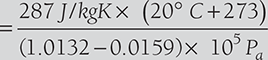
Enthalpy of water vapor, hs = cp × DBT + hfg = 4.18 kJ/kgK × 20° C + 2454.1 kJ/kg (from steam table)
Enthalpy of mixture per kg of dry air, hmix = ha + ω × hs
Specific volume of mixrure is equal to the volume of 1 kg of dry air, 
EXAMPLE 8.5
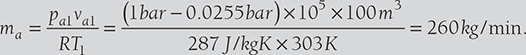
50 m3 of air at 20°C DBT and 15°C WBT are mixed with 20 m3 of dry air at 30°C DBT and 20°C WBT. Determine the DBT and WBT of the mixture.
SOLUTION
From psychrometric chart, at 20°C DBT and 15°C WBT, the psychrometric property values can be given as:
Va1 (Sp. Vol.) = 0.8412 m3/kg
ω1 = 0.00875 kg/kg of dry air,
h1 = 42.34 kJ/kg
m1 = 50/0.8412 = 59.43 kg of dry air
Similarly,
From the psychrometric chart, at 30°C DBT and 20°C WBT, the psychrometric property values can be given as:
Va2 (Sp. Vol.) = 0.8699 m3/kg
ω2 = 0.01076 kg/kg of dry air,
h2 = 57.71 kJ/kg
m1 = 20/0.8699 = 22.99 kg of dry air
(Use Psychrometric chart to find DBT and WBT at the mixture’s final specific humidity and enthalpy.)
EXAMPLE 8.6
The DBT and RH of air are 40°C and 70%, respectively. The atmospheric pressure is 1 bar. Determine the specific humidity and vapor pressure of moisture in the air. If 8 grams of water vapor is removed from the air and temperature is reduced to 30°C. Find the relative humidity and DPT.
SOLUTION
Relative humidity, 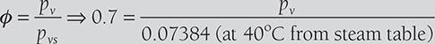
Specific humidity, 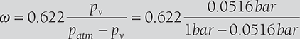
If 8 grams of water are removed from air, ω = 33.84 − 8 = 25.84 gram/kg

Relative humidity, 
EXAMPLE 8.7
100 m3 of air per minute at 30°C and 60% is cooled to 22°C DBT (sensible cooling). Find the heat removed from the air, relative humidity of the cooled air, WBT of cooled air (Take air pressure = 1 bar).
SOLUTION
From steam table, at 30° C DBT, pvs1 = 0.0425 bar
Relative humidity, ![]()
Specific humidity, ![]()
Enthalpy of water vapor mixture, h1 = Cpa.DBT + ω(Cpw.DBT + hfg )
At 22°C DBT, ω2-ω1= 0.0154 kg/kg of dry air
Relative humidity, 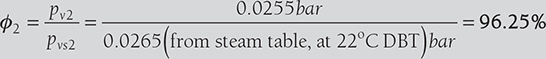
Enthalpy of water vapor mixture, h2 = Cpa.DBT + ω(Cpw.DBT + hfg )
8.9 AIR WASHERS
An air washer is a device for conditioning air. As shown in Figure 8.17, in an air washer air comes in direct contact with a spray of water and there will be an exchange of heat and mass (water vapor) between air and water. The outlet condition of air depends upon the temperature of water sprayed in the air washer. Hence, by controlling the water temperature externally, it is possible to control the outlet conditions of air, which then can be used for air conditioning purposes.
8.10 HUMAN COMFORT CONDITIONS
Air conditioning is the process whereby the condition of air, as defined by its temperature and moisture content, is changed as per requirement. In practice, other factors should also be taken into account especially cleanliness; odor, velocity, and distribution pattern. Comfort is a very subjective matter. The Engineer aims to ensure comfort for most people found from statistical surveys. Most people (90%) are comfortable when the air temperature is between 18–22°C and the % saturation is between 40–65%.
There are following general conditions required for human comfort
- Supply of oxygen per person should always be more than 0.65 m3 per person per hour.
- The amount of carbon dioxide should not be more than 2% in the air.
- The temperature range may vary from 22°C to 26°C.
- Humidity range may vary from 60% to 70%.
8.11 ROOM AIR CONDITIONER
Generally, two main types of room air conditioners are used; one is a window air conditioner and another is a split air conditioner. The details of the working of these air conditioners are discussed below:
8.11.1 Window Air Conditioner
The most common air conditioner, which is used for small houses and offices, is window air conditioner as shown in Figure 8.17. It is a cubical unit, a complete conditioning system in itself; it requires a window, or such space, where it can be installed with its face inside the room, and the exterior part outside the room, as it discharges heat outside. It is very easy to install. As compressor and evaporator, both are in one unit, so it’s cooling capacity is limited, this makes it suitable only for small places. The main components of a window AC are Compressor, Expansion valve, Hot condenser coil (exterior) Cold evaporator coil (interior) Two fans Control unit.
Front Panel
The front panel is that part of the window unit, which is seen inside from the room by the user. It has a user interface controlled either manually or through remote control. The older unit usually is of mechanical control type with rotary knobs to control the temperature and fan speed of the air conditioner. The newer units come with electronic control system where the functions are controlled using remote control and touch panel with digital display. The front panel has adjustable horizontal and vertical louvers to adjust the direction of air flow as per the desire of the user. The fresh intake of air called VENT (ventilation) is provided at the panel in the event that user would like to have a certain amount of fresh air from the outside.
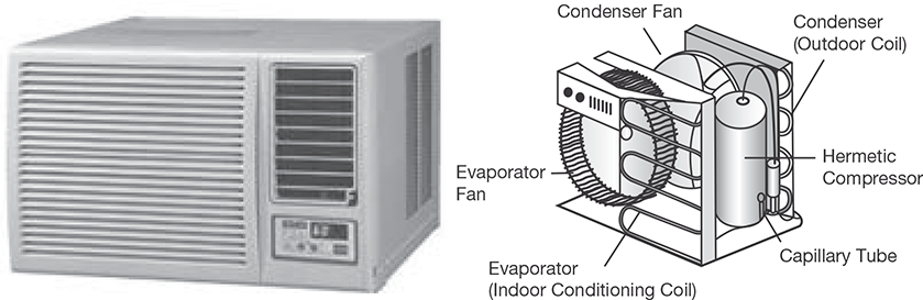
FIGURE 8.17
Window Air Conditioner and it Components
Indoor Side Components
The inside parts include:
- Cooling Coil with an air filter mounted on it. The cooling coil is where the heat exchange takes place between the refrigerant in the system and the air in the room.
- Fan Blower is a centrifugal evaporator blower to discharge the cool air to the room.
- Capillary Tube is used as an expansion device. It can be noisy while operating if it is installed too close to the evaporator.
- Operation Panel is used to control the temperature and the speed of the blower fan. A thermostat is used to sense the return air temperature and another one to monitor the temperature of the coil.
- Filter Drier is used to remove the moisture from the refrigerant.
- Drain Pan is used to collect the water that condensate from the cooling coil and is discharged out to the outdoor by gravity.
Outdoor Side Components
The outdoor side parts include:
- Compressor is used to compress the refrigerant.
- Condenser Coil is used to reject heat from the refrigerant to the outside air.
- Propeller Fan is used in the air-cooled condenser to help move the air molecules over the surface of the condensing coil.
- Fan Motor is located here. It has a double shaft where the indoor blower and outdoor propeller fan are connected together.
8.11.2 Split Air Conditioner
The split air conditioner comprises of two parts: the outdoor unit and the indoor unit (Figure 8.18). The outdoor unit consists of components like the compressor, condenser, and expansion valve fitted outside the room and the indoor unit consists of the evaporator or cooling coil and the cooling fan fitted inside the room. Split units have aesthetic looks and add to the beauty of the room. The split air conditioner can be used to cool one or two rooms.
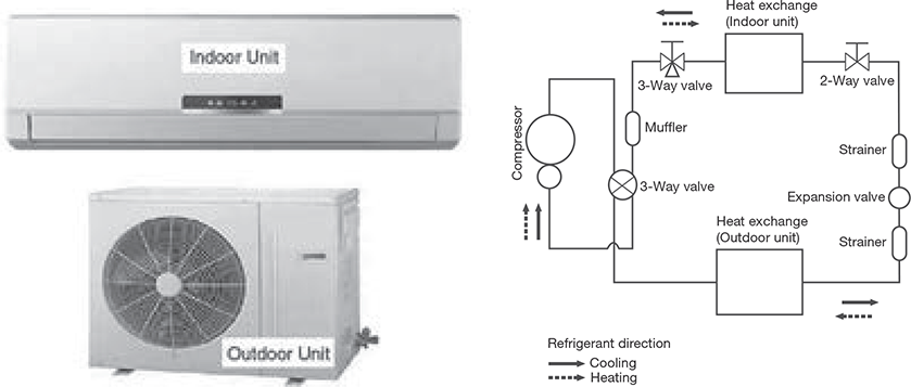
Since the compressor and condenser unit can be installed outside the room, inside the air conditioner feels calm and quiet. Split AC is an excellent option for office use and for large commercial buildings. Due to its compact size split AC is becoming popular even for household usage.
8.11.3 Difference Between Split and Window ACs
The working principle of both window AC and split AC are same, both but as they have different capacities, so both are used for different places. Split AC, being divided into two parts, has a large capacity, so it’s ideal for use in large offices and big rooms in the house. On the other hand, window AC is one unit conditioner, so it’s suitable for small rooms only. Window AC creates noise, whereas Split unit is found to be calm. Window AC is smaller in size as compared to split AC. Window AC is easy to install, but in the case of split AC, the exterior unit is to be connected to the interior unit through rubber tubes, which might cause troubles. Moreover, a window is necessary if you want to install window AC in your room, but for split AC, the interior unit will be connected to compressor unit through a small hole in the wall.
RECAP ZONE
Points to Remember
- The refrigeration unit transfers heat from cold to hot regions for the purpose of cooling the cold region while the heat pump does the same thing with the intent of heating the hot region.
- There are five basic components of a refrigeration system, these are: Evaporator, Compressor, Condenser, and Expansion Valve.
- The purpose of the evaporator is to remove unwanted heat from the product, via the liquid refrigerant.
- The purpose of the compressor is to draw the low-temperature, low-pressure vapor from the evaporator via the suction line. Once drawn, the vapor is compressed.
- The purpose of the condenser is to extract heat from the refrigerant to the outside air.
- Within the refrigeration system, the expansion valve is located at the end of the liquid line, before the evaporator.
- By passing the liquid refrigerant from the condenser through a heat exchanger through which the cold vapor at suction from the evaporator is allowed to flow in the reversed direction. This process subcools the liquid but superheats the vapor.
- If the vapor at the compressor entry is in the superheated state which is produced due to higher heat absorption in the evaporator, then the refrigerating effect is increased.
- The decrease in suction pressure decreases the refrigeration effect and at the same time increases the work of compression.
- The increase in discharge pressure results in lower COP.
- The factors like clearance volume, the pressure drop through discharge and suction values, leakage of vapor along the piston and superheating of cold vapor due to contact with hot cylinder walls, affects the volume of the vapor actually pumped by the compressor.
- Generally, two main types of room air conditioners are used; one is a window air conditioner and another is split air conditioner.
Important Formulae
- Coefficient of performance:
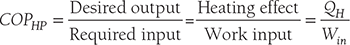 COPHP = COPR + 1
 - Tonnes of refrigeration: TR = Q × Cp × (Ti – To) / 3024= 210 kJ/min or 3.5 kJ/s
- COP of refrigerator:

- Volumetric efficiency of compressor:

- Saturation pressure at DPT = Pv
- Saturation pressure at DBT + Pvs
- Partial pressure of air, Pa = Patm − Pv
- Humidity ratio or specific humidity,

- Saturation pressure at DBT = Pvs
- Relative humidity,

- Mass of water vapor in mixture

- Enthalpy of water vapor mixture = C pa.DBT + ω(C pw.DBT + hfg )
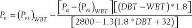
- If DPT is not given and only WBT and DBT are given then Pv can be calculated from Carrier’s equation as:
- Density of water vapor mixture
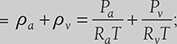 where Ra = 287 kJ/kg and Rv = 461kJ/kg
 - Enthalpy per kg of air

REVIEW ZONE
Multiple-choice Questions
- The cooling effect in refrigeration is obtained by:
- Mechanical refrigeration technique
- Passing a direct current through the junction of two dissimilar metals
- Sublimation of carbon dioxide
- Throttling of a real gas
Which of the above statements are correct?
- (i) and (ii)
- (i), (ii) and (iii)
- (i), (ii) and (iv)
- (i), (ii), (iii) and (iv)
- The cooling effect produced by refrigeration finds application in:
- Construction of cold storages
- Cooling of concrete in dams
- Comfort air conditioning of hospitals
- Liquification of gases and vapors
Select your answer from the following codes:
- (i) and (iii)
- (i), (ii) and (iii)
- (i), (iii) and (iv)
- (i), (ii), (iii) and (iv)
- A refrigeration system:
- Removes heat from a system at lowtemperature and transfers the same to a system at high-temperature
- Delivers less heat to the system at hightemperature than it extracts from the system at low-temperature
- Transfers heat from a high-temperature source to a low-temperature sink
- Violates second law of thermodynamics
- The COP of a Carnot refrigeration cycle decreases on:
- Decreasing the difference in operating temperatures
- Keeping the upper-temperature constant and increasing the lower-temperature
- Increasing the upper-temperature and keeping the lower-temperature constant
- Increasing the upper-temperature and decreasing the lower-temperature
- A Carnot refrigerating cycle used in house air conditioning delivers heat to the surroundings at the rate of 10 kw of power. The coefficient of performance of this refrigerator would be:
- 1.5
- 1.67
- 2.5
- 0.6
- If a Carnot cycle is to have a coefficient of performance of 5, the ratio of maximum temperature to minimum temperature in the cycle should be:
- 1.2
- 1.5
- 2.0
- 2.5
- A Carnot refrigerator rejects 3000 kj of heat at 400 k while using 1000 kj of work. The lowest operating temperature in the cycle should be:
- 15º C
- 27º C
- −6º C
- 0º C
- A Carnot engine has an efficiency of 80%, If the cycle is reversed in direction and made to operate as a refrigerator , its COP will be:
- 0.25
- 0.5
- 0.75
- 1.25
- A condenser of a refrigeration system rejects heat at a rate of 120 kw, while its compressor consumes a power of 30 kw. The coefficient of performance of the system would be:
- 2
- 3
- 4
- 5
- The operating temperature of cold storage is 280º k and the heat leakage from the surroundings is 35 kw for the ambient temperature of 310º k. If the actual COP of the refrigeration plant is onefourth of an ideal plant working between the same temperature limits, the power required to drive the plant would be:
- 3.7 kw
- 7.5 kw
- 12 kw
- 15 kw
- A Carnot heat pump for domestic heating works between a cold system ( the contents of refrigerator cabinet) at 0ºC and the water in the radiator system at 80ºC. The coefficient of performance of this heat pump would be about:
- 1.4
- 3.4
- 4.4
- 6.2
- A heat pump working on a reversed Carnot cycle has a COP of 5. If it is made to work as a refrigerator taking 1 KW of work input, the refrigerating effect will be:
- 1 KW
- 2 KW
- 3 KW
- 4 KW
- The capacity of refrigerating m/c is expressed as:
- Inside volume of cabinet
- Lowest temperature attained
- Gross weight of m/c in tons
- Rate of abstraction of heat from the space being cooled
- One TOR implies that the m/c has a refrigerating effect ( capacity of heat extraction from the system being cooled) equal to:
- 50 kCal/sec
- 50 kCal/min
- 50 kCal/hr
- 50 kCal/day
- One TOR is equivalent to:
- 1 KW
- 2.5 KW
- 3.5 KW
- 5 KW
- The domestic refrigerator has a refrigerating load of the order of:
- Less than 0.25 ton
- Between 0.5 and 1 ton
- More than 1 ton
- More than 5 ton
- The refrigerating capacity of 165 domestic refrigerators is approximately equal to:
- 0.05 ton
- 0.1 ton
- 2 ton
- 5 ton
- Round the clock cooling of an apartment having a load of 300 MJ/day requires an air conditioning plant of capacity about:
- 1 ton
- 5 ton
- 10 tons
- 25 tons
- The refrigerating system of passenger air craft works on reversed:
- Brayton cycle
- Atkinson cycle
- Ericsson cycle
- Carnot cycle
- A Bell-Coleman cycle is a reversed:
- Brayton cycle
- Atkinson cycle
- Ericsson cycle
- Carnot cycle
- The Bell-Coleman refrigeration cycle uses ______ as working fluid.
- Hydrogen
- Carbon dioxide
- Air
- Any inert gas
Answers
- d
- d
- a
- d
- a
- a
- b
- a
- c
- d
- c
- d
- d
- b
- c
- a
- b
- a
- a
- d
- c
Theory Questions
- Differentiate the working of refrigeration and heat pump, thermodynamically.
- Enumerate the various components used in a refrigerator and explain their working.
- Write advantages and disadvantages of air refrigeration cycle.
- Find the expression for COP using Reversed Carnot cycle and Bell Coleman cycle.
- Find the derivation for COP in Vapor Compression cycle.
- Explain the effect of subcooling and superheating on COP of Vapor Compression Cycle.
- Compare vapor compression and Reversed Carnot Cycle.
- Write advantages and disadvantages of Vapor Compression Cycle over Air Refrigeration Cycle.
- *Explain the working of vapor absorption cycle.
- What do you mean by sensible heating and sensible cooling?
- What do you mean by latent heating and latent cooling?
- Write notes on bypass factor and sensible heat factor.
- What are the human comfort conditions?
- What are the various types of refrigerators have been in the application? Explain them.
- Explain the various refrigerants used in refrigeration and air conditioning.
- Write short notes on Window Air Conditioner and Split Air Conditioner.
- *Differentiate between refrigeration and air conditioning, vapor compression refrigeration and vapor absorption refrigeration. With a neat sketch, explain the working of a room air conditioner.
- *Define the following: (i) COP, (ii) unit of refrigeration, and (iii) air conditioning.
- *Explain with neat sketch the principle and construction of vapor absorption refrigeration system.
- *What is refrigeration? What is refrigeration effect? Explain window air conditioner with neat sketch.
- *Explain with a neat sketch the working of a vapor compression refrigerator. Also draw p-h and T-s diagram for the same.
- *Define air-conditioning. Classify the air conditioning system in detail.
- *Define:
- Sensible heat
- Latent heat
- Dryness Fraction
- Enthalpy of evaporation
- *What should be the properties of common refrigerants?
- *Define air conditioning. State the basic component of air conditioning systems.
- *Sketch and explain split air conditioner?
- *Discuss about psychrometry and their properties?
- *Explain the working of domestic refrigeration system with a neat sketch?
- *Name any six properties of refrigerants.
- *Distinguish between a heat engine, a heat pump, and a refrigerator.
- *With a neat sketch of a room air-conditioner, explain its working principle.
Numerical Problems
- Carnot refrigeration cycle absorbs heat at 280 K and rejects heat at 310 K.
- Calculate the coefficient of performance of this refrigeration cycle.
- If the cycle is absorbing 1120 kJ/min at 280 K, how many kJ of work is required per second?
- If the Carnot heat pump operates between the same temperatures as the above refrigeration cycle, what is the coefficient of performance?
- How many kJ/min will the heat pump deliver at 310 K if it absorbs 1120 kJ/min at 280 K.
- The capacity of a refrigerator is 200 TR when working between –4°C and 22°C. Determine the mass of ice produced per day from water at 22°C. Also, find the power required to drive the unit. Assume that the cycle operates on reversed Carnot cycle and latent heat of ice is 336 kJ/kg.
- A glass of water is mixed with ice. The moisture from the air begins to condense on the surface of glass when the temperature of water comes 12°C. If the room temperature and pressure are 25°C and 1.01325 bars, Determine the partial pressure and mass of water vapor in grams per kg of dry air.
- The pressure and temperature of the mixture of air and water vapor at 1 bar and 22°C. The dew point temperature of the mixture is 12°C. Find partial pressure of water vapor in the mixture, relative humidity, specific humidity, enthalpy of mixture per kg of dry air, and specific volume of mixture per kg of dry air.
- 50 m3 of air at 18°C DBT and 12°C WBT are mixed with 20 m3 of dry air at 32°C DBT and 24°C WBT. Determine the DBT and WBT of the mixture.
- The DBT and RH of air are 38°C and 60% respectively. The atmospheric pressure is 1 bar. Determine the specific humidity and vapor pressure of moisture in the air. If 10 grams of water vapor is removed from the air and temperature is reduced to 28°C. Find the relative humidity and DPT.
- 80 m3 of air per minute at 32°C and 70% is cooled to 24°C DBT (sensible cooling). Find the heat removed from the air, relative humidity of cooled air, WBT of the cooled air (Take air pressure = 1 bar).
- *A perfect reversed heat engine is used for making ice at −5°C from water available at 25°C. The temperature of the freezing mixture is −10°C. Calculate the quantity of ice formed per kwh. For ice specific heat = 2.1 kJ/kg°k and latent heat = 335 kJ/kg.