
CHAPTER 9
Fluid Mechanics and Hydraulic Machines
Learning Objectives
By the end of this chapter, the student will be able:
- To understand the basic concepts of fluid mechanics and the force analysis
- To describe the construction details, design, and working of hydraulic turbines
- To describe the construction details, design, and working of hydraulic pumps
- To demonstrate the working of hydraulic coupling and torque converter
FLUID MECHANICS
9.1 INTRODUCTION
Engineering mechanics can be divided into three parts—mechanics of the rigid body, mechanics of solids, and mechanics of fluids. In the Mechanics of rigid body, it is assumed that there is no internal deformation in the body and we study about the static and dynamic position of the body subjected to external forces. In the mechanics of solid, it is assumed that the solid deforms subjected to external forces and we study about the nature of deformation in the body. In the fluid mechanics, shape and size of the body are not constant and we study about statics and dynamics of flow of fluid subjected to various types of forces on it.
9.2 PROPERTIES OF FLUIDS
The study of properties of fluids is a base for the basic understanding of flow or static condition of fluids. Some important properties of fluids are density, viscosity, surface tension, bulk modulus and vapor pressure, etc. Viscosity causes resistance to flow between two adjacent layers of fluid. Surface tension leads to capillary effects. Bulk modulus is involved in the propagation of disturbances like sound waves in fluids. Vapour pressure can cause flow disturbances due to evaporation at locations of low pressure. It plays an important role in cavitation studies in hydraulic machines.
9.2.1 Density
The fluid density is the quantity of fluid contained in its unit volume. It can be expressed in three different ways—mass density, specific weight, and relative density.
Mass Density
Mass Density (ρ) is defined as the mass of a substance per unit volume. S.I. unit of mass density is Kilograms per cubic meter, kg/m3 and dimensions is ML−3.
Specific Weight
Specific Weight (ω), sometimes γ, and sometimes known as specific gravity is defined as the weight per unit volume or the force exerted by gravity, g, upon a unit volume of the substance. The Relationship between g and ω can be determined by Newton’s 2nd Law, since weight per unit volume = mass per unit volume × g; ω ρ = g. S.I. unit of fluid is Newton per cubic meter, N/m3 and dimension is ML−2 T−2.
Relative Density
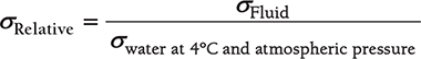
Relative Density (σ) is defined as the ratio of the mass density of a fluid to some standard mass density. For solids and liquids, this standard mass density is the maximum mass density for water (which occurs at 4° C) at atmospheric pressure.
9.2.2 Viscosity
Viscosity, μ is a property of a fluid which offers resistance to shear deformation. Different fluids deform at different rates under the same shear stress. Fluid with a high viscosity, such as lubricant oil deforms more slowly than the fluid with a low viscosity such as water.
In any fluid flow, layers move at different velocities and the fluid’s viscosity arises from the shear stress developed between the layers that ultimately oppose any applied force. The relationship between the shear stress and the velocity gradient can be understood as two plates closely spaced at a distance, ∂y and separated by a homogeneous substance. Assuming that the plates are of large area ‘A’ and that the lower plate is fixed. A force ‘F’ is applied to the upper plate. If this force causes the substance between the plates to undergo shear flow with a velocity gradient ∂u / ∂y, the substance is called a fluid.
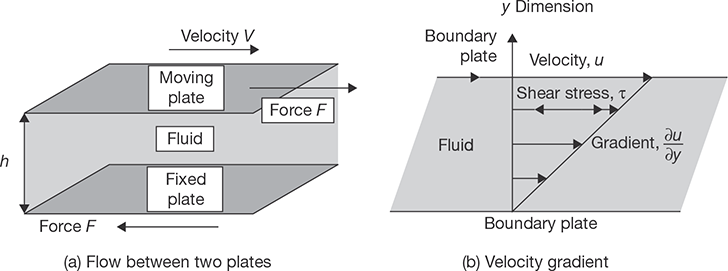
The applied force is proportional to the area and velocity gradient in the fluid. Combining these three relations results in the equation:
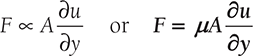
Where μ is proportionality constant called as viscosity.
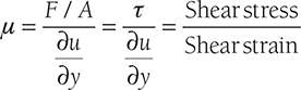
or 
Thus, for straight, parallel and uniform flow, the shear stress between layers is proportional to the velocity gradient in the direction perpendicular to the layers. This statement is known as Newton’s Law of Viscosity.
Here, μ is known as dynamic viscosity and its unit is Newton Second per square meter. The ratio of dynamic viscosity and density of the fluid is known as kinematic viscosity (v ). Its unit is meter2/sec. 1 stoke = 10–4m2/sec.
Variations in Viscosity with Temperature: The viscosity of liquid decreases with increase in temperature while the viscosity of gases increases with increase in temperature.
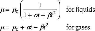
Where α and β are constants and t is the temperature. μ0 is the viscosity at 0° C.
EXAMPLE 9.1
The dynamic viscosity of lubricating oil used between shaft and sleeve is 10 poise. The diameter of the shaft, which rotates at 200 rpm, is 0.5 m. The sleeve length is 100 mm. Calculate the power lost if the thickness of oil film is 2 mm.
SOLUTION
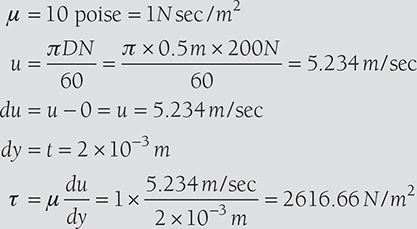
Shear force on the shaft, F = τ × A = 2616.66N / m2 × πDL
Torque on shaft, ![]()
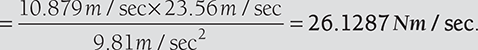
Power lost, ![]()
9.2.3 Newtonian and Non-newtonian Fluids
An ideal fluid has zero viscosity. Shear force is not involved in its deformation. An ideal fluid must be incompressible. Shear stress is zero irrespective of the value of ∂u / ∂y. Bernoulli equation can be used to analyze the flow. Real fluids having viscosity are divided into two categories, namely, Newtonian and non-Newtonian fluids. In Newtonian fluids, a linear relationship exists between the magnitude of the applied shear stress and the resulting rate of deformation. It means that the proportionality parameter, μ is constant in the case of Newtonian fluids. The viscosity at any given temperature and pressure is constant for a Newtonian fluid and is independent of the rate of deformation. The characteristics are shown plotted in Figure 9.2.
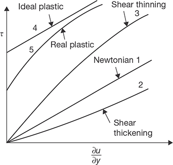
FIGURE 9.2
Type of Fluids
Non-Newtonian fluids can be further classified as simple non-Newtonian, ideal plastic and shear thinning, shear thickening and real plastic fluids. In non-Newtonian fluids, viscosity varies with variation in the rate of deformation. A linear relationship between shear stress and rate of deformation (∂u / ∂y) does not exist. In plastics, up to a certain value of applied shear stress, there is no flow. After this limit, it has a constant viscosity at any given temperature. In shear thickening materials, the viscosity increases with (∂u / ∂y) deformation rate. In shear thinning, materials viscosity decreases with ∂u / ∂y.
9.2.4 Surface Tension
Surface tension is the tendency of the surface of a liquid to behave like a stretched elastic membrane. There is a natural tendency for liquids to minimize their surface area. The obvious case is that of a liquid droplet on a horizontal surface that is not wetted by the liquid—mercury on glass, or water on a surface that also has a thin film of oil on it. All liquid molecules exhibit cohesive forces binding them with each other. This cohesive bond exhibits a tensile strength of the surface layer and this is known as surface tension.
Surface tension may also be defined as the work (in Nm/m2 or N/m) required to create a unit surface area of the liquid. The work is actually required for pulling up the molecules with lower energy from below, to form the surface. Another definition for surface tension is the force required to keep the unit length of the surface film in equilibrium (N/m). The formation of bubbles, droplets, and free jets are due to the surface tension of the liquid.
Surface Tension on Liquid Droplets: Let σ be the surface tension of the liquid, p be the pressure intensity inside the droplets, and d be the diameter of droplets. The tensile force due to surface tension acting around the circumference of the liquid droplets will be equal to pressure force on the projected area.
Surface Tension on a Hollow Bubble: A hollow bubble (such as soap bubble) has two surfaces in contact with air—one internal surface and another external surface. Thus, pressure force inside the bubble is equal to two times of tensile force on the bubble surfaces.
Surface tension on a liquid jet: ![]()
EXAMPLE 9.2
The surface tension of water in contact with air at ambient temperature is 0.10 N/m. The pressure inside the water droplet is 0.03 N/cm2 greater than the outside pressure. Calculate the diameter of the water droplet.
SOLUTION
Also, 
EXAMPLE 9.3
Find the surface tension in a soap bubble of 50 mm diameter when the inside pressure is 4 N/m2 above atmospheric pressure.
SOLUTION

9.2.5 Capillarity
Capillarity is a phenomenon of rise or fall of the liquid surface in a small tube relative to the adjacent general level of liquid when the tube is held vertically in the liquid. The rise of the liquid surface is known as capillary rise and fall of the liquid surface is known as capillary depression as shown in Figure 9.3.

Capillary Rise: Let h = height of liquid in the tube, σ = surface tension of the liquid, and θ = angle of contact between liquid and glass tube.

Capillary Depression: Let h = fall in height of liquid in the tube, σ = surface tension of the liquid, and θ = angle of contact between liquid and glass tube.

EXAMPLE 9.4
Calculate the capillary rise in a glass tube of diameter 2 mm when immersed vertically in: water and (ii) mercury. Assume surface tension for water as 0.07 and for mercury as 0.5 in contact with air. The specific gravity for mercury is 13.6 and angle of contact is 130°.
SOLUTION
Capillary rise for water at θ = 0

Capillary rise for mercury at θ = 130°
9.2.6 Pressure Variation with Depth
The interaction of the static fluid with its surroundings is in the form of force, which is applied equally on all contact points. This force is the result of the pressure applied on a particular unit area. The pressure in the fluid is not constant throughout. The pressure in any body of the fluid varies with depth and it increases with the depth of the fluid. But at the same level relative to the vertical direction the pressure will be same in the fluid. The increase in pressure as we go down the fluid is due to the weight of the fluid column above that level.

FIGURE 9.4
Forces Acting on Cylinder of Fluid
The variation of the pressure with the depth of the liquid column can be formulated with this simple analysis. Consider a vertical column of a liquid with a constant cross-sectional area. The liquid under consideration is at rest so there is no shear force acting or coming into the picture. The liquid column is in equilibrium so all the forces are balanced in the column. At any point in the column, the net force is zero. The weight of the column at any particular depth is balanced by the force due to pressure at that point. Thus, the pressure at that point is equal to the weight of the column at that point divided by the area of cross section of the liquid column.
Let P denote the pressure at the base of the cylinder; since p changes at a rate ![]() with elevation, the pressure is found from the definition of a derivative to be
with elevation, the pressure is found from the definition of a derivative to be  dz at the top of the cylinder. (Note that we do not anticipate a reduction of pressure with elevation here; hence, the plus sign is used. If indeed—as proves to be the case—pressure falls with increasing elevation, then the subsequent development will tell us that
 ![]() is negative.) Hence, the fluid exerts an upward force of pA on the base of the cylinder, and a downward force of
is negative.) Hence, the fluid exerts an upward force of pA on the base of the cylinder, and a downward force of 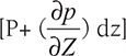 A on the top of the cylinder.
Next, apply Newton’s second law of motion by equating the net upward force to the mass times the acceleration which is zero, since the cylinder is stationary:
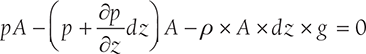
Cancellation of PA and division by Adz leads to the following differential equation, which governs the rate of change of pressure with elevation:

Note: Pressure at the depth h in a fluid of density ρ may be given as P = P0 + ρ × g× h, where P0 is pressure at the open surface of the fluid.
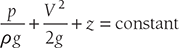
9.3 BERNOULLI’S EQUATION
The Bernoulli’s equation is an approximate relation between pressure, velocity, and elevation, and is valid in regions of steady and incompressible flow where net frictional forces are negligible. Despite its simplicity, it has proven to be a very useful tool in fluid mechanics. The key approximation in the derivation of the Bernoulli equation is that viscous effects are negligibly small compared to inertial, gravitational, and pressure effects. Since all fluids have a viscosity, this approximation cannot be valid for an entire flow field of practical interest. In other words, we cannot apply the Bernoulli equation everywhere in a flow, no matter how small the fluid’s viscosity. However, it turns out that the approximation is reasonable in certain regions of many practical flows. We refer to such regions as inviscid regions of flow, and we stress that they are not regions where the fluid itself is inviscid or frictionless, but rather they are regions where net viscous or frictional forces are negligibly small compared to other forces acting on fluid particles.

FIGURE 9.5
Forces on Fluid Element
Considering a streamline flow takes place in s-direction as shown in Figure 9.5. A small element of fluid of cross-sectional area dA and length ds is considered for force analysis. The forces acting on this element are given as:
- pressure force, pdA in the direction of flow,
- pressure force
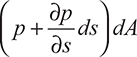 opposite to the direction of flow,
 - the weight of the fluid element, ρgdAds.
The resultant force on the fluid element in the direction of flow must be equal to the mass of fluid element X acceleration in the direction.

where as is acceleration in direction s.
Now, ![]() , where velocity, V is a function of s and t.
, where velocity, V is a function of s and t.
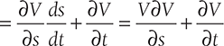
For steady flow, 


Therefore,

This is known as Euler’s Equation of motion.
Bernoulli’s equation is obtained by integrating the Euler’s equation of motion.
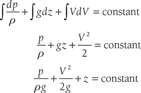
Here, ![]() represents the pressure energy per unit weight;
represents the pressure energy per unit weight;
![]() represents the kinetic energy per unit weight; 2g
represents the kinetic energy per unit weight; 2g
z represents the potential energy per unit weight.
EXAMPLE 9.5
The water is flowing through a pipe having diameters 30 cm and 20 cm at two sections 1 and 2, respectively. The rate of flow through the pipe is 80 liters/sec. Section 1 is 8 m above the datum and section 2 is 5 m above the datum. If the pressure at section 1 is 4 bar, find the intensity of pressure at section 2.
SOLUTION

From Bernouilli’s Equation, we get


9.4 TYPES OF FLOW
Steady and Unsteady Flow: Steady flow is that type of flow in which the fluid characteristics such as velocity, pressure, density, etc. at a point do not change with time. Unsteady flow is that type of flow in which the fluid characteristics such as velocity, pressure, density, etc. at a point change with time.
Uniform and Non-uniform Flow: Uniform flow is that type of flow in which velocity of the fluid does not change with respect to space. Non-uniform flow is that type of flow in which velocity of the fluid changes with respect to space.
Laminar and Turbulent Flow: Laminar flow is that type of flow in which the fluid particles move along well-defined paths of streamline and all the streamlines are straight and parallel to each other. This type of flow is also known as streamline or viscous flow. Turbulent flow id that type of flow in which fluid particles move in a zig–zag way. This zig–zag motion of the fluid particles results in eddies formation which is responsible for energy loss.
Compressible and Incompressible Flow: Compressible flow is that type of flow in which density of fluid changes from point to point. Incompressible flow is that type of flow in which density of fluid remains constant throughout the flow.
Rotational and Irrotational Flow: In rotational flow, fluid particles moving on stream lines also rotate about their axes. In irrotational flow fluid particles do not rotate about their axes, they smoothly move in stream line.
HYDRAULIC MACHINES
9.5 INTRODUCTION
Hydraulic machines are the devices that convert hydraulic energy into mechanical energy or mechanical energy into hydraulic energy. Hydraulic turbines are the basic prime movers which convert the hydraulic energy (in the form of pressure/kinetic energy) into mechanical energy. Pressure energy is developed due to the head of water in the form of potential energy and kinetic energy is developed due to the mass flow of water with some velocity. The shaft of hydraulic turbine rotates due to impact/reaction force of water on hydraulic blades; the shaft of the turbine is coupled to a generator which produces electrical energy. Pump converts mechanical energy into hydraulic energy (pressure energy).
9.6 HYDRAULIC TURBINES
9.6.1 Classification of Hydraulic Turbines
There is a number of the basis on which the classification of hydraulic turbines can be done. Some important bases among them are discussed below as:
- Energy Available at the Inlet of the Turbine
Impulse turbine: The energy available at the inlet of the turbine is kinetic energy. A jet of water impacts on the turbine blades mounted on the shaft and results in the shaft rotation at high speed. Impulse turbine works on the principle of impulse-momentum equation. The change in momentum of water produces impulse on the blades of the turbine, which acts as torque for rotation of turbine shaft. Example: Pelton turbine.
Reaction turbines produce back thrust or reaction on the blade due to the difference in pressure at inlet and outlet of the turbine. The pressure at the inlet of the reaction turbine is more than that of the outlet as the reverse of the impulse turbine in which pressure remains constant at inlet and outlet of the turbine. Example: Francis turbine and Kaplan turbine.
- Direction of Flow of Water
Tangential flow turbine: The turbine, in which water flows along the tangent of the runner, is known as tangential flow turbine. Example: Pelton turbine
Radial flow turbine: The turbine, in which water flows in a radial direction inward or outward, is known as radial flow turbine.
Axial flow turbine: The turbine, in which water flows through the runners along the of the turbine, is known as axial flow turbine. Example: Kaplan turbine.
Mixed flow turbine: The turbine, in which water flows through the runner in the radial direction but leaves the turbine in the axial direction, is known as mixed flow turbine. Example: Francis turbine.
- Head
High head turbine (Head > 180 meter). Example: Pelton Turbine.
Medium head turbine (60 < Head < 150 meter). Example: Francis turbine.
Low head turbine (30 < head < 60 meter). Example: Kaplan turbine.
- Specific Speed of the Turbine
Low specific speed turbine (10 to 35). Example: Pelton turbine.
Medium specific speed turbine (60-300). Example: Francis turbine.
High specific speed turbine (300-1000). Example: Kaplan turbine.
9.7 TERMINOLOGY USED IN TURBINE
Gross Head: It is the difference between the water level in reservoir and tail race and indicated by Hg.
Net Head: It is the net head available at the inlet of the turbine after deduction the various types of head losses due to friction, pipe bend, and fitting, etc.
where, 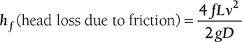
f is coefficient of friction,
L is length of penstock,
v is velocity of water, and
D is diameter of penstock.
Hydraulic Efficiency: It is the ratio of power delivered to runner and power available at the inlet of the turbine. Power at inlet of the turbine is more than the power supplied to the runner due to losses in flow through the runner

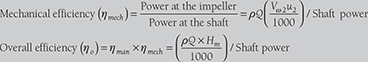
Mechanical Efficiency: It is the ratio of the power produced at the shaft of the turbine and power supplied to the runner of the turbine.

Volumetric Efficiency: It is the ratio of the actual volume of water striking the runner and the volume of water supplied to the turbine.

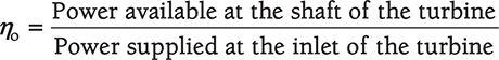
Overall Efficiency: It is the ratio of the power available at the shaft of the turbine and power supplied at the inlet of the turbine.
9.8 PELTON TURBINE
Pelton turbine is named after L. A. Pelton an American Engineer; it is a high head, tangential flow, and low specific speed turbine. This turbine is most suitable for the high head. In the case of low head, flow is to be increased and for increased flow, a bigger jet diameter is required. The bigger jet diameter requires bigger runner diameter, which results in the bulky turbine and low peripheral velocity. Thus, the efficiency of Pelton turbine decreases with a low head of the water. A Schematic diagram of Pelton turbine is shown in Figure 9.6.

FIGURE 9.6
General Layout of Pelton Turbine
9.8.1 Main Components of Pelton Turbine
Penstock: Penstock is a steel or concrete conduit, through which water flows from the reservoir to nozzle. Its size is large due to conduction of flow of water from the high head (200 m) to the nozzle.
Nozzle and Guiding Mechanism: The pressure head at the inlet of the turbine is converted into kinetic energy using the nozzle. The velocity of the of water jet at the tip of the nozzle depends on the net head (H); ![]() . The high velocity jet of water strikes on the bucket and deviates at 165° and results into impulse on the buckets. Buckets mounted on shaft rotate at high velocity and produce shaft power.
. The high velocity jet of water strikes on the bucket and deviates at 165° and results into impulse on the buckets. Buckets mounted on shaft rotate at high velocity and produce shaft power.
The guide mechanism is used to control the flow of water from the nozzle and to control the speed of the turbine as shown in Figure 9.6. The main function of the spear is to change the flow area of the nozzle moving in forward and backward directions. The flow area is decreased by the movement of the spear in the forward direction and increased by the movement of the spear in the backward direction. But, water in penstock causes hammering due to sudden increase and decrease pressure resulting from a sudden change in the flow area. Therefore, to prevent the high-pressure generation in the penstock, a deflector is used in front of the nozzle, which deflects the flow of water to decrease the shaft speed.
Bucket: The splitter, a sharp edge at the center of the bucket, divides it into two hemispherical part. The splitter helps the jet to be divided into two parts without producing a shock on the bucket and moving the same sideways in opposite directions. The rear of the bucket is so designed that water should not interfere during passage the bucket proceeding in order of rotation as shown in Figure 9.7. The jet should be deflected backward at an angle of 160° to 165°; the materials used for the bucket may be cast iron, bronze or stainless steel.
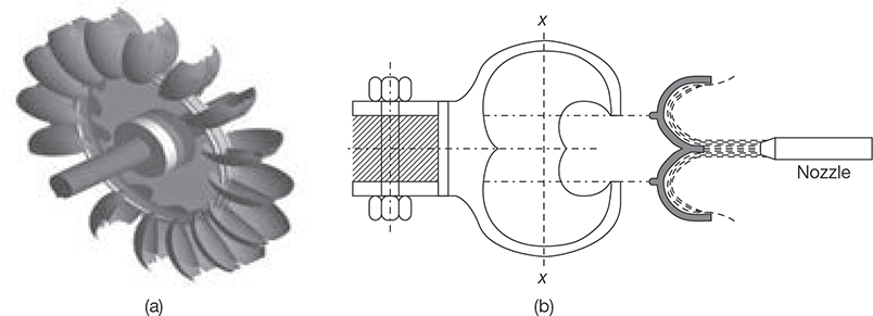
FIGURE 9.7
(a) Buckets of Pelton Wheel, and (b) Cross-sectional View of Bucket
Casing: Casing has no hydraulic importance; it is only used to prevent the splashing of water and to discharge the water to tail race; and the other purpose is to provide a safeguard to the wheel.
9.8.2 Selection of Speed of Pelton Turbine
Specific speed of the Pelton turbine ranges from 10 to 35. If the speed of the turbine is made higher, following changes may be required:
- Specific speed of turbine will increase.
- Size of the turbine will increase.
- The jet diameter will decrease to increase the jet ratio and turbine efficiency.
- Multiple jets will be required; the governing of multiple jet becomes complex.
- The number of poles required in the generator coupled with the turbine will be less due to high speed.
Hydraulic Brake: To stop the turbine quickly in short interval of time, some smaller nozzles are fixed in such a way that water jets strike the bucket from the back side.
9.8.3 Velocity Triangle for Pelton Turbine

FIGURE 9.8
(a) Velocity Triangle for Series of Radial Vane, and (b) Velocity Triangle for Pelton Turbine
Here, V1 and V2 are velocities of jet at inlet and outlet, respectively;
Vr1 and Vr2 are relative velocities of jet with respect to bucket at inlet and outlet, respectively;
u1 and u2 are bucket velocities at inlet and outlet, respectively;
Vf1 and Vf2 are velocities of flow, i.e., component of V1 and V2 in the direction of motion of bucket at inlet and outlet, respectively;
Vω1 and Vω2 are velocities of whirl at inlet and outlet, respectively;
α is an angle between the direction of jet and direction of motion of bucket;
θ is an angle between Vr1 and direction of motion of bucket;
β is an angle between V2 and direction of motion of bucket;
φ is an angle between Vr2 and direction of motion of bucket.
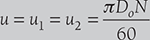
In the case of Pelton wheel, α = 0, θ = 0, u1 = u2 = u = πDN / 60, V1 = Vω1, Vr1 = V1 – u1= V1 – u
Where D is the diameter of wheel and N is rpm.
where H is net head equals to Hg − Hf.
Hg and Hf is gross and friction heads, respectively. Cv is coefficient of velocity.
From Velocity triangle in Figure 9.8 (b),
Force exerted by water on the bucket, Fx = m {Vω1 − (−Vω2 )} = ρ × a × V1 [Vω1 + Vω2 ]

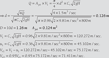
EXAMPLE 9.6
A Pelton turbine is coupled to an electric generator of 10000 kW. The head of water available at the nozzle is 800 m. Assuming generator efficiency as 95%, Pelton wheel efficiency as 85%, coefficient of velocity for nozzle as 0.96, speed ratio as 0.36, jet deflection angle by the bucket as 1650, and relative velocity at outlet as 0.95 times that of inlet, calculate: (i) diameter of jet, (ii) flow of water in m3, and (iii) force exerted by jet on bucket. If the ratio of bucket diameter to jet diameter is 10, find the synchronous speed for the generation at 50 cycles per second and the corresponding mean diameter of the runner.
SOLUTION
Given: P = 10000kW; H = 800 m; ηgen = 0.95; ηt = 0.85; Cv = 0.96; Cu = 0.36; ϕ
= 180° − 165° = 15°
Vr2 = 0.95Vr1; D / d = 10; f = 50 cycles /sec.
Power input to the generator, 
Power input to the turbine, 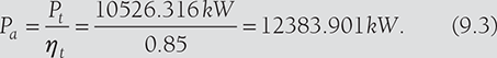
Also, Power available at the turbine, ![]()
From Equations (9.2) and (9.3), ![]()

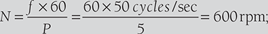
Frequency of generator, ![]() where P is number of pairs of poles and N is synchronous speed.
where P is number of pairs of poles and N is synchronous speed.
 Revised diameter
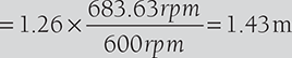
EXAMPLE 9.7
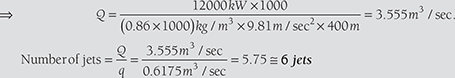
A Pelton wheel is to be designed with following specifications: Shaft power = 12000 kW, Head = 400m, Speed = 800 rpm, Overall efficiency = 86%, jet diameter is one-tenth of wheel diameter. Determine: (i) the wheel diameter, (ii) the number of jets required, and (iii) diameter of the jet. Assume Cv = 0.98 and Cu = 0.45.
SOLUTION
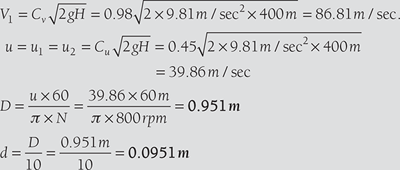
Discharge of one jet, ![]()
Overall efficiency, 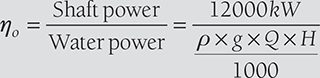
9.9 FRANCIS TURBINE
Initially, Francis turbine was designed as a pure radial flow reaction turbine by an American Engineer James B. Francis. Modern Francis turbine is mixed flow reaction turbine as water enters the turbine in radial direction and exits in the axial direction. It operates under medium heads and also requires a medium quantity of water. It is employed in the medium head power plants. It covers a wide range of heads from 30 to 150 m. Water is brought down to turbine from reservoir and directed to a number of stationary orifices fixed all around the circumference of a runner, which is known as guide vane.
Water head is partly converted into kinetic head and rest remains as pressure head. There is the difference in pressure between guide vane and runner, called as reaction pressure. The reaction pressure is responsible for the motion of the runner. Therefore, a Francis turbine is called a reaction turbine.
9.9.1 Main Components of Francis Turbine
There are following components of Francis Turbine (Figure 9.9)

FIGURE 9.9
Francis Turbine
Penstock: Penstock is a waterway to carry water from the reservoir to the turbine casing. It is very similar to all types of turbines.
Spiral or Scroll Casing: In a spiral casing, the cross sectional area decreases around the periphery of guide wheel from the entrance to tip. A spiral casing is shown in Figure 9.9. This type of casing used to prevent the eddy formation that causes the loss in efficiency.
Guide Vane: Guide vanes have aerofoil cross-section to reduce the friction loss and prevent the eddies formation. Each guide vane can turn about its pivot by means of regulating shaft and link connected to guide vane so that it can be opened or closed to allow the passage for the variable quantity of water according to the needs. The regulating shaft is operated by means of a governor whose function is to keep the speed constant to the turbine at varying loads.
Runner: Runner is fixed to the turbine shaft. Water flows, radially inward to the runner and exits axially. For high specific speed runner, it is wider than low specific speed runner, since it has to handle a large amount of water. It is made of corrosion resistant materials.
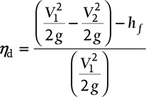
Draft Tube: If the water is discharged freely from the runner, the effective head of the turbine will be reduced and will be equal to the height of the reservoir from runner outlet. So a taper draft tube is used at the outlet of the turbine to increase the head of water by the height of the draft tube. Since there is a big loss of head due to high kinetic energy at the outlet of the turbine. The loss is recovered by converting these kinetic head into pressure head at the exit of the draft tube. It is mainly used in reaction turbine.

FIGURE 9.10
Draft Tube
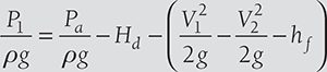
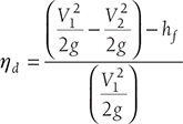
Let Hd is the height of the draft tube above the tailrace and x is a distance of the bottom of the draft tube from tailrace level. From Bernoulli’s Equation “Total energy at any section during flow remains constant”.
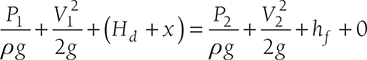
Where hf is loss of energy due to function in draft tube

From the above equation, it can be observed that P1 < Pa
9.9.2 Different Shapes of Draft Tubes

FIGURE 9.11
Different Types of Draft Tubes
Velocity Triangle for Francis Turbine
Here, V1 and V2 are velocities of jet at inlet and outlet, respectively;
Vr1 and Vr2 are relative velocities of jet with respect to bucket at inlet and outlet, respectively;
u1 and u2 are bucket velocities at inlet and outlet, respectively;
Vf1 and Vf2 are velocities of flow, i.e., component of V1 and V2 in the direction of motion of bucket at inlet and outlet, respectively;
Vω1 and Vω2 are velocities of whirl at inlet and outlet, respectively;
α is an angle between the direction of jet and direction of motion of bucket;
θ is an angle between Vr1 and direction of motion of bucket;
β is an angle between V2 and direction of motion of bucket;
φ is an angle between Vr2 and direction of motion of bucket.

FIGURE 9.12
Velocity Triangle for Francis Turbine
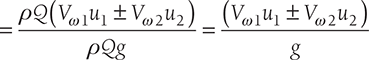
The work done per second on runner by water,
Where ![]()
The work done per second per unit weight of water
Here, +ve sign is taken if β < 90°; –ve sign is taken if β > 90°, and Vω2 = 0, if β = 90°.
In case of Francis turbine β = 90
Now, work done per second per unit weight of water 

EXAMPLE 9.8
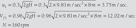
A Francis turbine working under a head of 8 m. The overall efficiency is 70% and power required to produce 150 kW. The peripheral and radial velocities at inlet are ![]() and
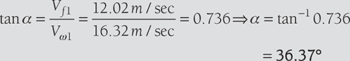
and ![]() , respectively. The wheel runs at 160 rpm and hydraulic efficiency of the turbine is 78%. Assuming radial discharge, find (i) the guide blade angle, (ii) vane angle at inlet, (iii) diameter of the wheel at the inlet, and (iv) width of the wheel at the inlet.
, respectively. The wheel runs at 160 rpm and hydraulic efficiency of the turbine is 78%. Assuming radial discharge, find (i) the guide blade angle, (ii) vane angle at inlet, (iii) diameter of the wheel at the inlet, and (iv) width of the wheel at the inlet.
SOLUTION
There is radial discharge at outlet, therefore Vω2 = 0 and Vf2 = V2.
Hydraulic efficiency, 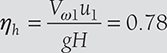

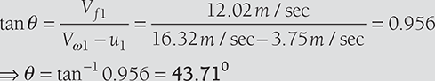
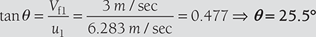
- Guide blade angle, α
- Wheel vane angle at inlet, θ
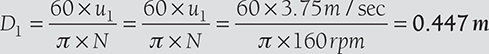
- Diameter of wheel at inlet, D1
- Width of the wheel at inlet, b1

EXAMPLE 9.9
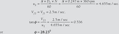
An inward flow reaction turbine rotates at 360 rpm. The wheel vanes are radial at the inlet and the inner diameter of the wheel is half of the outer diameter. The constant velocity of flow in the wheel is 2.5 m/sec. Water enters the wheel at an angle of 150 to the tangent at the wheel at the inlet. The width of the wheel at the inlet is 90 mm and area of flow blocked by vane is 2% of the gross area of flow at the inlet. Assuming radial discharge, find (i) head available, (ii) vane angle at the outlet, (iii) the outer and inner diameter of the wheel, and (iv) the theoretical water power developed by the wheel.
SOLUTION
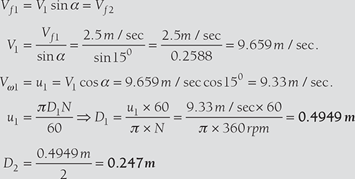
Head available, ![]()
Quantity of water flow, Q = area of flow × velocity of flow
Water power, ![]()
9.10 KAPLAN TURBINE
Kaplan turbine is an axial flow, low head, high specific speed, reaction type turbine. There is a similar turbine known as propeller turbine having fixed vane in place of the adjustable vane as in Kaplan turbine.
Kaplan turbine has following components (Figure 9.13 and 9.14):
Scroll Casing: Its function is very similar to scroll casing in Francis turbine as explained earlier. It reduces the eddies formation and hence minimizes the eddy loss.
Guide Mechanism: It has a similar function as in Francis turbine.
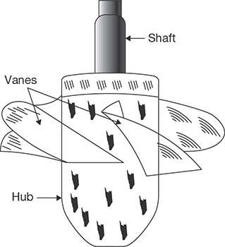
Hub, Vane/Runner: The extended bottom end of the shaft is known as hub boss. On the periphery of boss 3 to 6 vanes are mounted that are fixed in propeller turbine and adjustable in Kaplan turbine. Propeller turbine is used where head and load are constant but Kaplan turbine is used where load and head are variable. During operation, vanes are adjusted by Servomotor mechanism. Servomotor mechanism consists of a cylinder with a piston working under oil pressure on either side.

FIGURE 9.13
Main Components of Kaplan Turbine
9.10.1 Velocity Triangle for Kaplan Turbine
Area of flow at inlet ![]() , where D0 is outer diameter of runner and Db is hub diameter.
, where D0 is outer diameter of runner and Db is hub diameter.
Velocity of flow at inlet = Velocity of flow at outlet
i.e., Vf1 = Vf2
Peripheral velocity at inlet and outlet are equal, ![]()
Discharge through runner, ![]()

FIGURE 9.15
Velocity Triangle for Kaplan Turbine
EXAMPLE 9.10
A Kaplan turbine is working under a head of 20 m. The hub diameter is 0.25 times the runner diameter. The rpm of the turbine is 500. Runner angle at the outlet is 15° and flow ratio is 0.6. Calculate: (i) diameter of runner and (ii) discharge rate of water.
SOLUTION
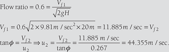
For kaplan turbine, u1 = u2 = 44.3555m / sec.

Discharge rate ![]()
EXAMPLE 9.11
A Kaplan turbine is designed to develop 7000 kW shaft power. The head available is 10 m. Assuming speed ratio as 2.1, flow ratio as 0.6, overall efficiency as 70%, and diameter of the boss as one-third of the diameter of runner. Find the diameter of runner and its speed.
SOLUTION
Speed ratio, 
Flow ratio, 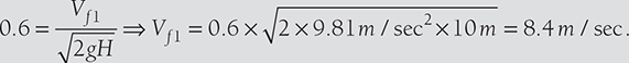

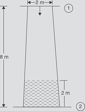
EXAMPLE 9.12
A conical draft tube having inlet and outlet diameters 2 m and 2.5 m discharges water at the outlet with a velocity of 3 m/sec. The total length of the draft tube is 8 m out of which 2 m of the length of the draft tubes immersed in water. If atmospheric pressure head is 10.3 m of water and loss of head due to friction in the draft tube is equal to 0.2 times of velocity head at the outlet of the tube. Find: (i) pressure head at inlet and (ii) Efficiency of draft tubes.
SOLUTION
D1 = 2 m, D2 = 2.5 m, V2 = 3 m/s

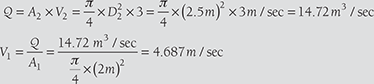
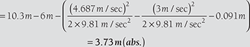
- Pressure head at inlet,
- Efficiency of draft tube,
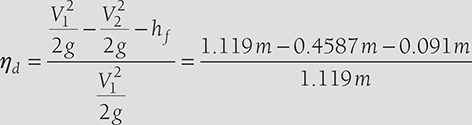 = 50.87 %
Cavitation
Cavitation is defined as the phenomenon of formation of vapor bubbles due to fall in pressure below its vapor pressure and sudden bursting of these bubbles in a high-pressure zone. It is an undesirable phenomenon.
Effects of Cavitation
- Cavities are formed on the surface and metallic surface is damaged.
- Due to sudden collapse of vapor bubbles, considerable noise and vibrations are produced.
- The efficiency of turbine decreases.
Cavitation depends on vapor pressure, absolute or barometric pressure, suction pressure, and effective dynamic head and absolute velocity of water at runner exit.
Precaution against Cavitation
- Pressure of flowing fluid at any part should not fall below vapor pressure.
- Specific materials or coating such as aluminum, bronze, and stainless steel, which are capitation resistant materials should be used.
9.11 GOVERNING OF TURBINES
Governing of turbines is required to control the speed of the turbine since it is coupled with an electric generator with fixed number of poles provided in the generator. The speed of the turbine is controlled by controlling the water flow. This is done by means of a governor, which is running due to the motion of the shaft of the turbine. There is a servomotor in which cylinder and piston are used to control the flow area of water by a spear. If the turbine speed increases due to decreasing load on the generator, the speed is reduced by decreasing the flow of water with the help of spear movement controlled by piston and cylinder servomotors.
9.12 PUMPS
Working principle of hydraulic pumps is the just reverse of the hydraulic turbines. Hydraulic turbine transforms the hydraulic energy into mechanical work whereas hydraulic pump transforms mechanical work into hydraulic energy. The pumps may be a reciprocating type or rotary type. Centrifugal pump is a rotary type pump, which is used for large delivery and small head and the reciprocating pump is used for small delivery and high head.
9.13 CENTRIFUGAL PUMP
Centrifugal pump works on the reverse of the principle of working of radial inward flow reaction turbine. The pressure at the periphery will be high due to centrifugal force on the water. The centrifugal force is subjected on the water due to forced vortex motion. Water enters in the axial direction and leaves radial direction (Figure 9.16). The pressure is proportional to the square of radius as a rise in pressure head.
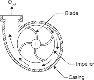
FIGURE 9.16
Construction Feature of Centrifugal Pump
Due to high-pressure head at the periphery, water can be lifted to a higher level.
9.13.1 Main Components of Centrifugal Pump
Main components of a centrifugal pump are Impeller, casing, suction pipe, foot valve, strainer, delivery pipe as further discussed.
Impeller: Impeller is a backward curved vane. It is mounted on the shaft coupled to the electric motor. Thus, it is a rotating part of centrifugal pump.
Casing: It is air tight passage surrounding the pump. Its function is to convert the kinetic energy of water into pressure energy before entering the delivery pipe. Different types of casing used in the centrifugal pump are volute casing, vortex casing, and casing with guide blade as shown in Figure 9.17 (a), (b), and (c).
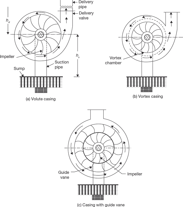
FIGURE 9.17
Different Types of Casing Used in Centrifugal Pump
The volute casing is a spiral type casing. The area of the passage increases gradually so that velocity of water decrease and pressure increases. The main limitation of this casing is eddies formation which causes the loss of energy. In vortex casing, eddies formation is eliminated by employing a circular chamber in between impeller and casing as shown in Figure 9.17 (b). Thus, the efficiency of vortex casing is more than that of volute casing.
Casing with guide blades allows water to enter into the guide blade without shocks. Guide blade works as a diffuser, since the area of guide blade increases, which converts the kinetic energy of water into pressure energy.
Suction Pipe, Foot-valve, and Strainer: A pipe, whose one end is connected to the inlet of the pump and other end dips into the water in a sump, is known as a suction pipe. A foot valve is a non-return type valve which is fitted with the lower end of the suction pipe. The foot valve opens only in upward direction. A strainer is also fitted at the lower end of the suction pipe. It works as a filter.
Delivery Pipe: A pipe, whose one end is connected to the outlet of the pump and other end is connected to the supply at some height, is known as a delivery pipe.
9.13.2 Velocity Triangle for Centrifugal Pump
Here,
- N is the speed of impeller in rpm;
- D1, D2 are diameter of impeller at inlet and outlet, respectively;
- U1, u2 are tangential velocities at inlet and outlet, respectively;
- V1, V2 are absolute velocities of water at inlet and outlet, respectively;
- Vr1, Vr2 are the relative velocities of water at inlet and outlet;
- α is an angle made by absolute velocity V1 at the inlet with the direction of motion of vane;
- θ is an angle between Vr1 and the direction of motion of vane;
- β, φ are the corresponding angles of α and θ at the outlet.

FIGURE 9.18
Velocity Triangle for Centrifugal Pump
The Water enters the impeller radially, therefore α =0., Vω1 = 0.
Work done per unit weight of water by impeller
Work done by impeller on water per second = ρQVω2u2
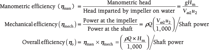
9.13.3 Various Heads and Efficiencies of Centrifugal Pumps
Suction Head, hs: It is height of center (eye) of the pump from water level.
Delivery Head, hd: It is the height of the tank from the center of the pump.
Static Head, Hs: it is the sum of suction and delivery heads, i.e., Hs = hs + hd
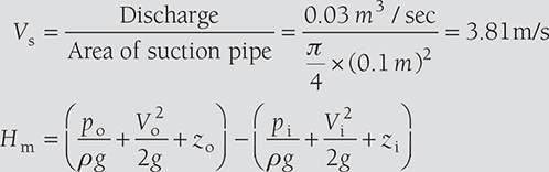
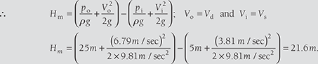
Manometric Head, Hm: It is the head against which a centrifugal pump has to work.
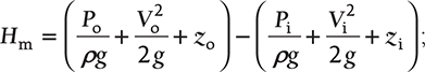
where subscript o is used for outlet and i is used for inlet.
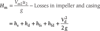
where hfs is friction loss in suction pipe; hfd is friction loss in delivery pipe, and Vd is discharge velocity
9.13.4 Some Important Points Related to Centrifugal Pump
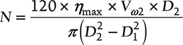
- Minimum speed required for starting a centrifugal pump:
- In multistage centrifugal pump:
- For high head, pumps are coupled in series
- For high discharge, pumps are coupled in parallel
- Specific speed,

- Priming of centrifugal pump: Priming of a centrifugal pump is defined as the operation in which the suction pipe, casing of the pump and a part of the delivery pipe up to the delivery valve is completely filled with water and air from these parts of the pump is removed.
EXAMPLE 9.13
A centrifugal pump running at 1,500 rpm has internal and external impeller diameter of 200 mm and 300 mm, respectively. The vane angles of the impeller at inlet and outlet are 25° and 30°, respectively. If water enters the impeller radially and velocity of flow remains constant. Determine the work done by the impeller per unit weight of water.
SOLUTION

Work done by impeller per kg of water per second 
EXAMPLE 9.14
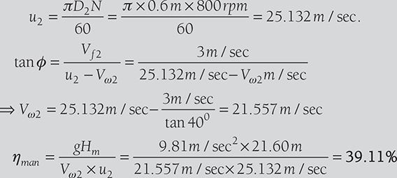
A centrifugal pump having an internal and external diameter of impeller 150 mm and 600 mm, respectively, is running at 800 rpm. It has a constant velocity of flow of 3 m/sec and discharges through the pump are 0.03 m3/sec. The diameters of suction and delivery pipes are 100 mm and 75 mm, respectively and suction and delivery heads are 5 m and 25 m of water, respectively. If outlet vane angle is 40° and power required to drive the pump is 15 kW, determine: (i) vane angle at the inlet, (ii) overall efficiency of the pump, and (iii) manometric efficiency of the pump.
SOLUTION
Given: D1 = 150 mm; D2 = 600 mm; N = 800 rpm; Vf1 = Vf2 = 3 m/s; Q = 0.03 m3/s; ds = 100 mm; dd = 75 mm; Hs = 5 m; Hd = 25 m; ϕ = 40; P = 15kW.


EXAMPLE 9.15
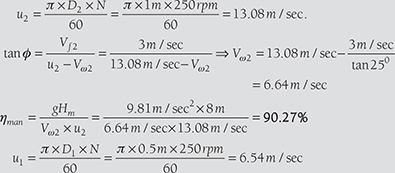
Following data of a centrifugal pump are given as: Diameter at inlet = 0.5 m; Diameter at outlet = 1.0 m; Speed = 250 rpm; Flow rate = 1800 liters/sec; Vane exit angle = 25°; Velocity of flow = 3 m/sec; head = 8 m. Find the least speed to start the pump and manometric efficiency.
SOLUTION

9.14 RECIPROCATING PUMP
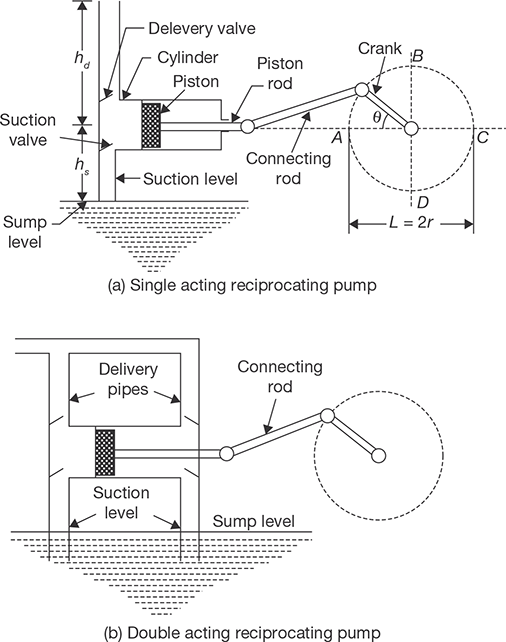
In a centrifugal pump, the transformation of energy from mechanical to hydraulic form is done by rotating action of the impeller, but in the reciprocating pump, this energy transformation is done by the reciprocating action of the piston. In a reciprocating pump, the rotary motion of crankshaft is converted into the reciprocating motion of pump by means of a connecting rod. Pressure on water is applied by reducing the volume by positive displacement method.
The main components of the reciprocating pump are a cylinder, piston, or plunger, connecting rod, crank, suction pipe, and delivery pipe as shown in Figure 9.19. Suction and delivery pipes are connected to the cylinder through one-way valves. In a single acting reciprocating pump, piston moves towards right through 0° to 180° of the crank and small vacuum is created inside the cylinder. Due to this vacuum, suction valve is pushed up and water enters into the cylinder. When the piston moves towards right through 180° to 360° of crank rotation, suction valve is closed and the delivery valve is open due to the high pressure of water. Thus, water is forced into the delivery pipe and raised to a required height.
Discharge through centrifugal pump,

Slip: It is difference between theoretical and actual discharge of reciprocating pump
Variation in Acceleration Head in the Suction and Delivery Pipes Due to Acceleration of the Piston
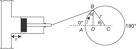
FIGURE 9.20
Velocity and Acceleration of Piston
Pressure head due to acceleration in suction and delivery pipes:
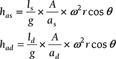
where A is area of piston and as and ad areas of suction and delivery pipes, respectively.
Thus, acceleration heads depend on the value of θ.
Variation in Friction Head in Suction and Delivery Pipes Due to Variation in Velocity of Piston
Head loss due to friction is given by
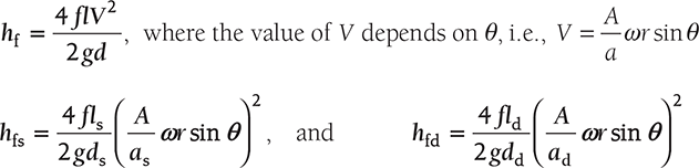
At θ = 90° head loss due to friction will be maximum and at θ = 0° head loss will be zero.
Case I: When acceleration heads and friction heads are zero.
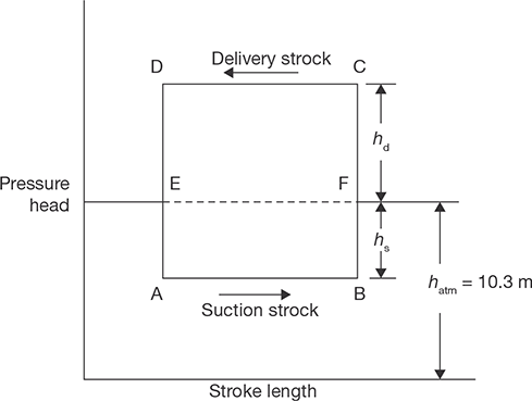
FIGURE 9.21
Ideal Indicator Diagram without Acceleration and Friction Heads
Case II: When acceleration heads are not equal to zero.
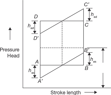
FIGURE 9.22
Indicator Diagram, When Acceleration Heads are not Equal to Zero, But Friction Heads are Zero.
Case III: When acceleration heads and friction heads are not equal to zero
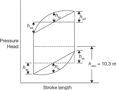
FIGURE 9.23
Indicator Diagram, When Acceleration Heads and Friction Heads are not Equal to Zero
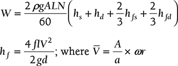
Work done by pump for a single acting reciprocating pump

Work done by pump for a double acting reciprocating pump
9.14.1 Air Vessels
Air vessel is a closed chamber containing compressed air in the top space and liquid at the bottom of the chamber. At the base of the chamber, there is an opening through which the liquid (water) may flow into or out from the vessel. When liquid enters the air vessel, air gets compressed and when liquid exits from the vessel, the air gets expanded. An air vessel is fitted to the suction pipe and to the delivery pipe at a point close to the cylinder of a single acting reciprocating pump. The purposes of its application are as given below:
- to obtain a continuous supply of liquid at a uniform rate,
- to save a considerable amount to work in overcoming the friction resistance in the suction and delivery pipes, and
- to run the pump at high speed without separation.
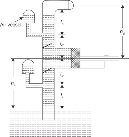
FIGURE 9.24
Reciprocating Pump with Air Vessels
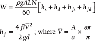
Work done by reciprocating pump with air vessels fitted to suction and delivery pipes
Work done by reciprocating pump with air vessels fitted to suction and delivery pipes
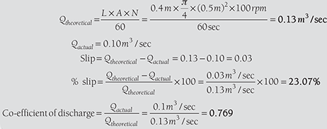
EXAMPLE 9.16
A single acting reciprocating pump running at 100 rpm delivers 0.10 m3/sec of water. The diameter of the piston is 500 mm and the stroke length is 400 mm. Determine: (i) the theoretical discharge, (ii) percentage slip, and (iii) coefficient of discharge.
SOLUTION
EXAMPLE 9.17
A double acting reciprocating pump has a piston of 300 mm diameter and piston rod of 60 mm diameter. Stroke length is 400 mm and speed is 50 rpm. The suction and discharge heads are 8 m and 18 m, respectively. Determine: (i) the force required to run the pump during in and out strokes, (ii) quantity of water in m3/sec raised by the pump, and (iii) power required to run the pump.
SOLUTION
Given: D = 300 mm; d = 60 mm; L = 400 mm; N = 50rpm; Hs = 8 m; and Hd = 18 m
- Force required during in-stroke, F = ρg [ A × Hs + (A − a)Hd ]

-


9.15 GEAR PUMP
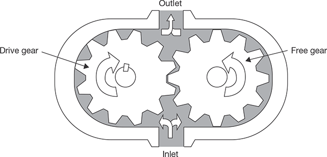
FIGURE 9.25
Schematic Diagram of Gear Pump
A gear pump maintains the flow of fluid by carrying the fluid between the teeth of two meshed gears. One gear is connected to drive shaft and other is meshed with the first gear. The pumping chambers formed between the gear teeth are enclosed by the pump housing and the side plates. A low-pressure region is created at the inlet as the gear teeth separate. As a result, fluid flows in and is carried around by the gears. As the teeth mesh again at the outlet, high pressure is created and the fluid is forced out. Figure 9.25 shows the construction of an internal gears pump; most of the gear type pumps are fixed displacement. They range in output from very low to high volume. Usually, they operate at comparatively low pressure.
9.16 VANE PUMP
In a vane pump, a rotor is coupled to the drive shaft and rotates inside a cam ring. Vanes are fitted to the rotor slots and follow the inner surface of the ring as the rotor turns (Figure 9.26). Centrifugal force and pressure under the vanes keep them pressed against the ring. Pumping chambers are formed between the vanes and are enclosed by the rotor, ring, and two side plates. At the pump inlet, a low-pressure region is created as the space between the rotor and ring increases. Oil entering here is trapped in the pumping chambers and then is forced into the outlet as the volume decreases.
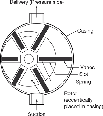
FIGURE 9.26
Vane Pump
9.17 LOBE PUMP
This is also used to pump oils. The schematic diagram of a lobe pump is shown in Figure 9.27. This is a three-lobed pump. The two-lobed pump is also used. Two lobes are arranged in a casing. As the rotor rotates, oil is trapped in the space between the lobe and the casing and is carried to the pressure side. Helical lobes along the axis are used for the smooth operation. Oil has to be filled before starting the pump. The constant contact between the lobes makes a leak tight joint preventing oil leakage from the pressure side. The maximum pressure of operation is controlled by the back leakage through the clearance. This type of pump has a higher capacity compared to the gear pump.

FIGURE 9.27
Lobe Pump
9.18 SCREW PUMP
There are many variants screw type positive displacement, rotary pump. The various design depends on the number of intermeshing screws involved, the pitch of the screws, and the direction of fluid flow. Two common designs are the two-screw, low-pitch, double-flow pump, and the three-screw, high-pitch, double-flow pump.
9.18.1 Two-screw, Low-pitch, Screw Pump
The two-screw, low-pitch, screw pump consists of two crews of right handed and left handed threads mesh with close clearances, mounted on two parallel shafts. The driving shaft drives the other shaft through a set of herringbone timing gears. The gears maintain the clearances between the screws as they rotate and to promote quiet operation. The screws rotate in closely fitting duplex cylinders that have overlapping bores. All clearances are small, but there is no actual contact between the two screws or between the screws and the cylinder walls.

FIGURE 9.28
Two-screw, Low-pitch, Screw Pump
The complete assembly and the flow diagram are shown in Figure 9.28. The liquid is trapped at the outer end of each pair of screws. As the first space between the screw threads rotates away from the opposite screw, a one-turn, spiral-shaped quantity of liquid is enclosed when the end of the screw again meshes with the opposite screw. As the screw continues to rotate, the entrapped spiral turns of the liquid slide along the cylinder toward the center discharge space while the next slug is being entrapped. Each screw works in similar fashion, and each pair of screws discharges an equal quantity of liquid in opposed streams toward the center, thus eliminating hydraulic thrust. The removal of liquid from the suction end by the screws produces a reduction in pressure, which draws liquid through the suction line.
9.18.2 Three-screw, High-pitch, Screw Pump
The three-screw, high-pitch, screw pump has many of the same elements as the two-screw, low-pitch, screw pump, and their operations are similar as shown in Figure 9.29. Three screws, oppositely threaded on each end, are employed. They rotate in a triple cylinder, the two outer bores of which overlap the center bore. The pitch of the screws is much higher than in the low pitch screw pump; therefore, the center screw, or power rotor, is used to drive the two outer idler rotors directly without external timing gears. Pedestal bearings at the base support the weight of the rotors and maintain their axial position. The liquid being pumped enters the suction opening, flows through passages around the rotor housing, and through the screws from each end, in opposed streams, toward the center discharge. This eliminates unbalanced hydraulic thrust. The screw pump is used for pumping viscous fluids, usually lubricating, hydraulic, fuel oil, etc.

RECAP ZONE
Points to Remember
- In fluid mechanics, shape and size of the body are not constant and we study about statics and dynamics of flow of fluid subjected to various types of forces on it.
- The fluid density is the quantity of fluid contained in its unit volume. It can be expressed in three different ways—mass density, specific weight, and relative density.
- Viscosity, μ is a property of a fluid, which offers resistance to shear deformation.
- In any fluid flow, layers move at different velocities and the fluid’s viscosity arises from the shear stress developed between the layers that ultimately oppose any applied force.
- An ideal fluid has zero viscosity.
- Shear force is not involved in its deformation.
- An ideal fluid must be incompressible.
- In Newtonian fluids, a linear relationship exists between the magnitude of the applied shear stress and the resulting rate of deformation.
- Surface tension is the tendency of the surface of a liquid to behave like a stretched elastic membrane.
- Surface tension may also be defined as the work (in Nm/m2 or N/m) required to create a unit surface area of the liquid.
- Capillarity is a phenomenon of rise or fall of the liquid surface in a small tube relative to the adjacent general level of liquid when the tube is held vertically in the liquid.
- The Bernoulli’s equation is an approximate relation between pressure, velocity, and elevation, and is valid in regions of steady and incompressible flow where net frictional forces are negligible.
- Hydraulic machines are the devices that convert hydraulic energy into mechanical energy or mechanical energy into hydraulic energy.
- Hydraulic turbines are the basic prime movers which convert the hydraulic energy (in the form of pressure/kinetic energy) into mechanical energy.
- Pump converts mechanical energy into hydraulic energy (pressure energy).
- Pelton turbine is named after L. A. Pelton an American Engineer; it is a high head, tangential flow, and low specific speed turbine.
- Initially, Francis turbine was designed as a pure radial flow reaction turbine by an American Engineer James B. Francis.
- Modern Francis turbine is mixed flow reaction turbine.
- A taper draft tube is used at the outlet of the turbine to increase the head of water by the height of the draft tube.
- Kaplan turbine is an axial flow, low head, high specific speed, reaction type turbine.
- Cavitation is defined as the phenomenon of formation of vapor bubbles due to fall in pressure below its vapor pressure and sudden bursting of these bubbles in a high-pressure zone.
- Governing of turbines is required to control the speed of the turbine.
- Centrifugal pump works on the reverse of the principle of working of radial inward flow reaction turbine.
- In a reciprocating pump, this energy transformation is done by the reciprocating action of the piston.
- A gear pump maintains the flow of fluid by carrying the fluid between the teeth of two meshed gears.
- Hydraulic coupling is used to transmit the power from one shaft to another.
Important Formulae
-


 for liquid droplets
 for soap bubble
  for liquid jet
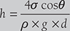

- Hnet = Hg − hf
where, hf (head loss due to friction)

f is coefficient of friction,
L is length of penstock,
v is velocity of water, and
D is diameter of penstock.


- For Pelton Turbine,
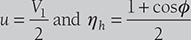
- For maximum efficency,
- Efficiency of draft tube,
- For radial flow reaction Turbine:
The work done per second per unit weight of water

- For Francis Turbine Vω2 = 0:
Work done per second per unit weight of water


- For Kaplan Turbine:
Peripheral velocity at inlet and outlet are equal,
Discharge through runner,

- For Centrifugal pump:

Work done by impeller on water per second = ρQVω2u2

- Minimum speed required for starting a centrifugal pump

- In multistage centrifugal pump
- For high head, pumps are coupled in series;
- For high discharge, pumps are coupled in parallel
Specific speed,

- Priming of centrifugal pump: Priming of a centrifugal pump is defined as the operation in which the suction pipe, casing of the pump and a part of the delivery pipe up to the delivery valve is completely filled with water and air from these parts of the pump is removed.
- For Reciprocating pump:

where A is area of piston and as and ad area as of suction and delivery pipes, respectively.

Atθ = 90° head loss due to friction will be maximum and at θ = 0° head loss will be zero.
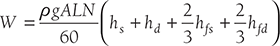
- Work done by pump for a single acting reciprocating pump
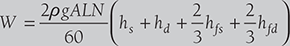
- Work done by pump for a double acting reciprocating pump
- Work done by reciprocating pump with air vessels fitted to suction and delivery pipes
- Work done by reciprocating pump with air vessels fitted to suction and delivery pipes
REVIEW ZONE
Multiple-choice Questions
- Fluid is a substance that:
- Cannot be subjected to shear force
- Always expands until it fills any container
- Has the same shear stress at a point regardless of its motion
- Cannot remain at rest under action of any shear force
- A fluid is said to be ideal, if it is:
- Incompressible
- Inviscous
- Viscous and incompressible
- Inviscous and incompressible
- The volumetric change of the fluid caused by a resistance is known as:
- Volumetric strain
- Compressibility
- Adhesion
- Cohesion
- Surface tension:
- Acts in the plane of the interface normal to any line in the surface
- Is also known as capillarity
- Is a function of the curvature of the interface
- Decrease with fall in temperature
- The stress-strain relation of the Newtonian fluid
is:
- Linear
- Parabolic
- Hyperbolic
- None of these
- Unit of surface tension is:
- Energy per unit area
- Force per unit length
- Both
- None of these
- Capillary action is due to the:
- Surface tension
- Cohesion of the liquid
- Adhesion of the liquid molecules and the molecules on the surface of a solid
- All of the above
- The rise or fall of head ‘h’ in a capillary tube of
diameter ‘d’ and liquid surface tension ‘σ’ and
specifi c weight ‘w’ is equal to:


- None of these
- Cavitation will begin when:
- The pressure at any location reaches an absolute pressure equal to the saturated vapor pressure of the liquid
- Pressure becomes more than the critical pressure
- Flow is increased
- Pressure is increased
- Bernoulli’s theorem deals with the conservation of:
- Mass
- Force
- Momentum
- Energy
- Euler’s equation in the differential form for motion of liquids is given by:
- A fluid which obeys

- Real fluid
- Perfect fluid
- Newtonian fluid
- None of these
- The speed of turbine and discharge through turbine are proportional to:
- Head, H

- H2
- H3/2
- Specific speed of a turbine depends on:
- Speed, power, and discharge
- Discharge and power
- Speed and head
- Speed, power, and head
- An impulse turbine:
- Operates submerged
- Requires draft tube
- Is nor exposed to atmosphere
- Operates by initial complete conversion to kinetic energy
- A Pelton wheel is:
- Tangential flow turbine
- Axial flow turbine
- Radial flow turbine
- Mixed flow turbine
- Pelton wheels are used for minimum heads of:
- 20 m
- 100 m
- 125 m
- 180 m
- The ratio of width of bucket for a Pelton wheel to the diameter of jet is of the order of:
- 15
- 14
- 13
- 12
- Impulse turbine is used for:
- Low head
- High head
- Medium head
- High flow
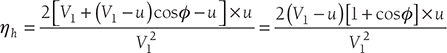
- If α is the angle of blade tip at outlet, then maximum hydraulic efficiency of an impulse turbine is:
- Francis turbine is best suited for:
- Medium head application (24 to 180 m)
- Low head installation (less than 30 m)
- High head installation (more than 180 m)
- None of these
- In reaction turbine, draft tube is used:
- To transport water downstream without eddies
- To convert the kinetic energy to pressure energy by a gradual expansion of the flow cross-section
- For safety of turbine
- To increase flow rate
- Francis, Kaplan and propeller turbines fall under the category of:
- Impulse turbine
- Reaction turbine
- Axial-flow turbine
- Mixed flow turbine
- For pumping viscous oil, the pump used is:
- Centrifugal pump
- Reciprocating pump
- Screw pump
- None of these
- The work requirement of a reciprocating pump
with increase in acceleration head:
- Increases
- Decreases
- Remains same
- None of these
- To avoid cavitation in centrifugal pumps:
- Suction pressure should be low
- Delivery pressure should be low
- Suction pressure should be high
- Delivery pressure should be high
- Overall effi ciency of centrifugal pump is equal to:
- Volumetric efficiency × manometric efficiency × mechanical efficiency
- Volumetric efficiency/manometric efficiency × mechanical efficiency
- Volumetric efficiency × manometric efficiency/mechanical efficiency
- Volumetric efficiency/manimetric efficiency/ mechanical efficiency
- The action of centrifugal pump is that of a:
- Reaction turbine
- Impulse turbine
- Reverse of reaction turbine
- None of these
- In double acting reciprocating pump compared to single acting reciprocating pump will have nearly:
- Double efficiency
- Double head
- Double flow
- Double weight
- Specific speed of pump is:
- Power required to drive a centrifugal pump is proportional to:
- Impeller diameter (D)
- D2
- D3
- D4
- Power required to drive a centrifugal pump is proportional to:
- Speed (N)
- N2
- N3
- N4
Theory Questions
- What do you understand by fluid mechanics? How does it differ from mechanics of solid or mechanics of the rigid body?
- Classify the fluids based on their properties.
- Derive the Bernoulli’s equation.
- Derive the rise and fall of capillary action in a tube.
- Derive an equation for pressure on a submerged body in a fluid.
- What do you mean by a hydraulic turbine? How do you classify the hydraulic turbines?
- Explain the working of Pelton turbine with a neat sketch.
- Discuss the governing of Pelton turbine.
- Derive the expression for work done and mechanical efficiency of Pelton turbines.
- How does a hydraulic turbine differ from the hydraulic pump?
- What are the different types of the efficiency of a turbine? Define each.
- Draw inlet and outlet velocity triangle for Pelton turbine and find expression for hydraulic efficiency.
- Establish a relationship between jet velocity and bucket velocity for maximum efficiency of Pelton turbine?
- What is the basis of turbine selection at a particular place?
- Define velocity coefficient, speed ratio, flow ratio, and jet ratio.
- What are the ranges of specific speed and head of Pelton, Francis, and Kaplan turbines?
- What is a draft tube? Why is it used in a reaction turbine? Describe with a neat sketch.
- What is the centrifugal pump? How is it different from Francis turbine?
- *Explain the working of a centrifugal pump with a neat sketch.
- Differentiate between the volute and vortex casing of a centrifugal pump.
- Explain different types of the efficiency of the centrifugal pump.
- Find the expression for the work done by impeller of a centrifugal pump on water per second per unit weight of water.
- *What is priming? Why is it required in a centrifugal pump?
- What is the reciprocating pump? Explain its working with a neat sketch.
- What are the slip and coefficient of discharge?
- What is air vessel? What are the functions of air vessel?
- Draw indicator diagram and show acceleration head, friction head on the diagram.
- *Explain the working of the double acting reciprocating pump and bucket pump with a neat sketch.
- What is the function of the pump? Classify the pumps. Explain with a sketch the working of the single acting reciprocating piston pump.
- *Explain the working principle of vane pump with a neat sketch?
- *What is the range of specific speed for Pelton, Francis, and Kaplan turbine?
- *Explain how a hydraulic reaction turbine differs from a hydraulic impulse turbine.
- *Discuss and draw the constructional details of Pelton turbine.
- *With the help of neat sketch, explain the working of a Francis turbine.
- *Explain the principle and working of reaction turbine.
- *Define radial flow, axial flow, and mixed flow with respect to water turbine.
- *How are water turbines classified?
- *Sketch and explain the working of a Kaplan turbine.
Numerical Problems
- The dynamic viscosity of lubricating oil used between shaft and sleeve is 12 poise. The diameter of the shaft, which rotates at 240 rpm, is 0.5m The sleeve length is 120 mm. Calculate the power lost if the thickness of oil film is 2.5 mm.
- The surface tension of water in contact with air at ambient temperature is 0.12 N/m. The pressure inside the water droplet is 0.02 N/cm2 greater than the outside pressure. Calculate the diameter of the water droplet.
- Find the surface tension in a soap bubble of 60 mm diameter when the inside pressure is 5 N/m2 above atmospheric pressure.
- Calculate the capillary rise in a glass tube of diameter 1.8 mm when immersed vertically in: (i) water and (ii) mercury. Assume surface tension for water as 0.07 and for mercury as 0.5 in contact with air. The specific gravity for mercury is 13.6 and angle of contact is 130°.
- The water is flowing through a pipe having diameters 32 cm and 18 cm at two sections 1 and 2, respectively. The rate of flow through the pipe is 100 L/sec. Section 1 is 8 m above the datum and section 2 is 8 m above the datum. If the pressure at section 1 is 5 bar, find the intensity of pressure at section 2.
- A penstock supplies water to Pelton turbine with a head of 80 m. One-third of head is lost in penstock due to friction. The flow rate of water from the nozzle is 2.5 m3/sec. The deflection angle of the jet is 165°. Speed ratio, Cu = 0.45 and Cv =0.95. Calculate power developed by the turbine and its hydraulic efficiency.
- A Pelton wheel is to be designed with following specifications:
Shaft power = 10,000 kW, Head = 500 m, Speed = 500 rpm, Overall efficiency = 85%, jet diameter is one-tenth of wheel diameter. Determine: (i) the wheel diameter, (ii) the number of jets required, and (iii) diameter of the jet. Assume Cv = 0.98 and Cu = 0.46.
- A Francis turbine working under a head of 10 m. The overall efficiency is 75% and power required to produce 180 kW. The peripheral and radial velocities at inlet are 0.3
 and 0.96 , respectively. The wheel runs at 200 rpm and hydraulic efficiency of the turbine is 84%. Assuming radial discharge, find: (i) the guide blade angle, (ii) vane angle at inlet, (iii) diameter of the wheel at the inlet, and (iv) width of the wheel at the inlet.
 - An inward flow reaction turbine rotates at 420 rpm. The wheel vanes are radial at the inlet and the inner diameter of the wheel is one-third of the outer diameter. The constant velocity of flow in the wheel is 2.8 m/sec. Water enters the wheel at an angle of 150 to the tangent at the wheel at the inlet. The width of the wheel at the inlet is 85 mm and area of flow blocked by vane is 2.5% of the gross area of flow at the inlet. Assuming radial discharge, find: (i) head available, (ii) vane angle at the outlet, (iii) the outer and inner diameter of the wheel, and (iv) the theoretical water power developed by the wheel.
- A Kaplan turbine is working under a head of 18 m. The hub diameter is 0.25 times the runner diameter. The rpm of the turbine is 550. Runner angle at the outlet is 15° and flow ratio is 0.6. Calculate: (i) diameter of runner and (ii) discharge rate of water.
- A Kaplan turbine is designed to develop 8,000 kW shaft power. The head available is 12 m. Assuming speed ratio as 2.1, flow ratio as 0.6, overall efficiency as 80%, and diameter of the boss as one-third of the diameter of runner. Find the diameter of runner and its speed.
- A conical draft tube having inlet and outlet diameters 2.5 m and 3.0 m discharges water at the outlet with a velocity of 5 m/sec. The total length of the draft tube is 10 m out of which 3 m of the length of the draft tubes immersed in water. If atmospheric pressure head is 10.3 m of water and loss of head due to friction in the draft tube is equal to 0.2 times of velocity head at the outlet of the tube. Find: (i) pressure head at inlet, and (ii) Efficiency of draft tubes.
- A centrifugal pump running at 2,000 rpm has internal and external impeller diameter of 250 mm and 350 mm, respectively. The vane angles of the impeller at inlet and outlet are 25° and 30°, respectively. If water enters the impeller radially and velocity of flow remains constant. Determine the work done by the impeller per unit weight of water.
- A centrifugal pump having an internal and external diameter of impeller 150 mm and 450 mm, respectively, is running at 1,000 rpm. It has a constant velocity of flow of 5 m/sec and discharges through the pump is 0.04 m3/sec. The diameters of suction and delivery pipes are 100 and 80 mm, respectively and suction and delivery heads are 8 and 20 m of water, respectively. If outlet vane angle is 30° and power required to drive the pump is 18 kW. Determine: (i) vane angle at the inlet, (ii) overall efficiency of the pump, and (iii) manometric efficiency of the pump.
- Following data of a centrifugal pump are given as: Diameter at inlet = 0.4 m; Diameter at outlet = 1.0 m; Speed = 400 rpm; Flow rate = 2000 liters/sec; Vane exit angle = 30°; Velocity of flow = 3 m/sec; head = 10 m. Find the least speed to start the pump and Manometric efficiency.
- A double acting reciprocating pump has a piston of 400 mm diameter and piston rod of 40 mm diameter. Stroke length is 300 mm and speed is 60 rpm. The suction and discharge heads are 8 m and 18 m, respectively. Determine: (i) the force required to run the pump during in and out strokes, (ii) quantity of water in m3/sec raised by the pump, and (iii) power required to run the pump.
- A single acting reciprocating pump running at 50 rpm delivers 0.10 m3/sec of water. The diameter of the piston is 600 mm and the stroke length is 500 mm. Determine: (i) the theoretical discharge, (ii) percentage slip, and (iii) coefficient of discharge.