
CHAPTER 21
Mechanical Working of Metals, Sheet Metal Work, Powder Metallurgy, and Smithy
Learning Objectives
By the end of this chapter, the student will be able:
- To differentiate hot working and cold working
- To describe the various mechanical forming processes
- To demonstrate the various tools used in sheet metal operations To describe the sheet metal processes
- To demonstrate the powder metallurgy processes
- To describe the various processes and tools used in Smithy
MECHANICAL WORKING PROCESS
21.1 INTRODUCTION
Mechanical working is a process of shaping of metals by plastic deformation. When a metal is subjected to an external force beyond yield strength but less than the fracture strength of the metal, metal is deformed by slip or twin formation. There are two types of mechanical working process:
- Cold working.
- Hot working.
When metal is deformed between room temperature and recrystallization temperature, it is called cold working. This process is suitable for highly ductile metal. Recrystallization temperature is the temperature at which the crystal structure of the metal starts to change. For low ductility, hot working is used. When metal is deformed between recrystallization temperature and a melting point of the metal, it is called hot working. In this process, the crystal structure of the metal is not deformed or distorted but it is rearranged.
Comparison between Cold Working and Hot Working
| Cold working | Hot working |
|---|---|
|
Advantages:
Disadvantages:
|
Advantages:
Disadvantages:
|
21.1.1 Advantages of Mechanical Working Process Over other Manufacturing Processes
- They have higher productivity compared to other manufacturing processes.
- Forged products have higher strength, better corrosion and wear resistance as compared to the casting and machined processes.
- There is minimum wastage of materials.
- The forged products have high dimensional accuracy and surface finish.
- Some special products like thin foil, wire, sheet steel and other products can be manufactured by only mechanical working.
Recrystallization Temperature: According to ASME (American society of mechanical engineers). The recrystallization temperature is defined as “the approximate minimum temperature at which the complete recrystallization of cold worked metal occurs within a specified period of time. Recrystallization reduces the strength and increases the ductility of the metal.
Factors which affect the recrystallization temperature:
- Grain size: Smaller grain size decreases recrystallization temperature.
- The function of time: Recrystallization temperature depends on the function of time of heating.
- Type of metal: For pure metal, it is lower in comparison to alloys.
- The extent of prior cold work: Higher the prior cold work, lower will be recrystallization temperature.
- Rate of deformation: Increasing the rate of deformation decreases the recrystallization temperature.
For pure metal, critical temperature, (Tcr) =0.3 Tm.
For Alloys, Tcr =0.5 Tm, where, Tm is a melting temperature.
21.2 ROLLING
Rolling is the process of reducing the thickness or changing the cross-sectional area of the workpiece by means of rolling mills. It is performed through hot working or cold working. The metal is drawn into the opening between the rolls by frictional forces between the metal and roll surface as shown in Figure 21.1. The metal is subjected to high compressive force between the rolls for deformation.

FIGURE 21.1
A Schematic Diagram of Rolling Process
21.2.1 Terminology
Bloom: 150 × 150 mm2 to 250 × 250 mm2.
Billet: 50 × 50 mm2 to 125 × 125 mm2.
Slab: Thickness: 50 to 150 mm, Width: 0.6 to 1.5 m.
Sheet and Plate: Maximum thickness: 6.35 mm.
Foil: 1.5 mm thickness.
21.2.2 Types of Rolling Mills
The different types of rolling millsare shown in Figure 21.2.
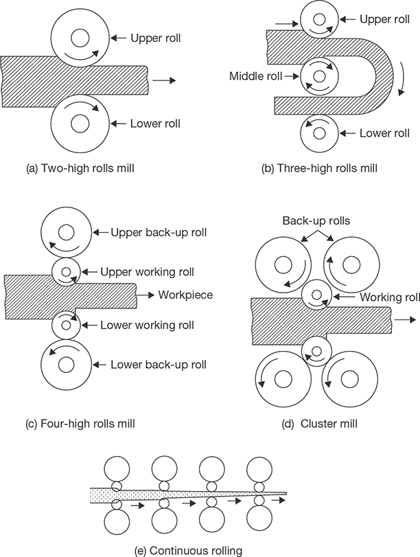
FIGURE 21.2
Types of Rolling Mills
In two high rolls mill (Pullover), the stock is returned to the entrance for further reduction. In two-high mill (reversing), the work can be passed back and forth through the rolls by reversing their direction of rotation. In three high rolls mill, upper and lower rolls are the driver and the middle roll rotates by friction. In four high rolls mill, small-diameter rolls of less strength and rigidity are supported by larger-diameter backup rolls. In cluster mill, each of the work rolls is supported by two backing rolls. Continuous rolling uses a series of rolling mill and each set is called a stand. The strip moves at different velocities at each stage in the mill.
21.2.3 Rolling Defects
There are two types of rolling defects: Surface Defects and Internal Defects as shown in Figures 21.3 and 21.4 respectively.
- Surface defects: Scale, rust, scratches, cracks, pits, and gouges.
- Internal structural defects: Wavy edges, crack in the center of the sheet (Zipper cracks), edge cracks, folds, etc.
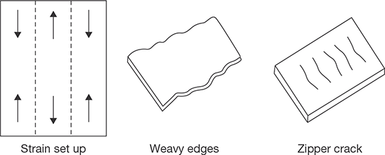
FIGURE 21.3
Surface Rolling Defects
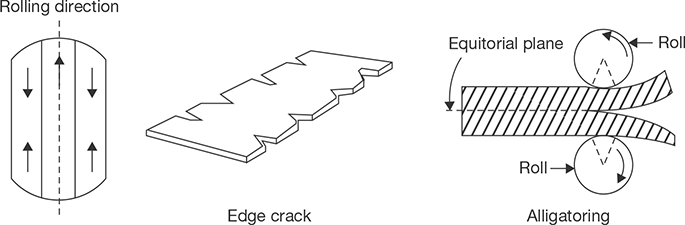
FIGURE 21.4
Internal Rolling Defects
21.3 FORGING
Forging is a process of plastic deformation for shaping. The force applied in this case is an intermittently compressive force while in a rolling process force applied is a continuous compressive force.
Advantages
- Homogeneous distribution of impurities.
- Porosity, voids and blow holes are largely eliminated.
- Refinement of grains and increase in strength.
- Fiber flow lines are properly directed, hence, better mechanical properties.
- Close dimensional tolerance, smooth surface.
Disadvantages
- Poor surface finish due to oxidation and scaling of the surface in hot forging.
- High operation cost.
- Complicated shape cannot be produced by this process.
21.3.1 Different Types of Forging
Open Die Forging
In open die forging, the hot workpiece is placed between two flat dies and is hammered to produce the desired shape. There is no flow of metal in this process. This is a slow process and may be performed by presses in addition to hammer (Figure 21.5a). It is repeatedly manipulated between the dies until the final shape is achieved. Cogging is a successive deformation of a bar along its length using an open-die drop forge. It is commonly used to work a piece of raw material to the proper thickness. Once the proper thickness is achieved the proper width is achieved via edging. Edging is the process of concentrating material using a concave shaped open die. The process is called edging because it is usually carried out on the ends of the workpiece. Fullering is a similar process that thins out sections of the forging using a convex shaped die. These processes prepare the workpieces for further forging processes.
Limitations of Open Die Forging
- It is limited to short run production.
- It has less control on mechanical properties and dimensions.
- It is restricted to simple shapes only.
- Machining is often required after forging.
- It has poor material utilizations.
Closed Die Forging
This is a variation of impression-die forging without flash (Figure 21.5b). It has better utilization of material than open flat dies, better physical properties, closer dimensional, tolerance, high production rate, etc. In impression-die forging the heated workpiece is placed between two required shaped die and is pressed or hammered. During hammering or pressuring it takes the shape of the die. A small amount of material is forced outside the die impression, which is finally trimmed. The flash helps to build up pressure on the material between the dies which ensures the filling of dies cavity.
Advantages
- There is saving of time because trimming is not required in this process.
- There is a better utilization of work materials.
- It has excellent reproductivity with good dimensional accuracy.
- Forging of complicated shape may be made.
- The products have good mechanical properties due to proper control of grain flow of the metal.
- It has high production rate.
Disadvantage
- Tooling cost is high, therefore, it is suitable for a large production run.
Drop Forging
In this forging, the metal is deformed by the impact of a hammer or die and hot metal is forced to confirm the die shape. The proper flow of metal during the intermittent blows is ensured and operation is divided into a number of steps. Each step changes the shape of the workpiece progressively. For complex forgings, more than one set of dies may be required.
Press Forging
Press forging employs a slow squeezing action produced by mechanically or hydraulically operated press as compared to rapid impact blows of hammer in drop forging. The slow squeezing action penetrates completely through the metal producing a more uniform deformation and flow of metal during the process. In this process, there is maximum utilization of energy by the workpiece while is drop forging some part of the energy is transferred to machine and foundation. The dimensional accuracy is also very good in this process.
Advantages of Press Forging over Drop Forging
- It produces low Noise level.
- It is faster than drop forging since only one squeeze is needed at each die impression.
- Control of two die halves is easier than hammering in drop forging.
- The product has superior structural quality.
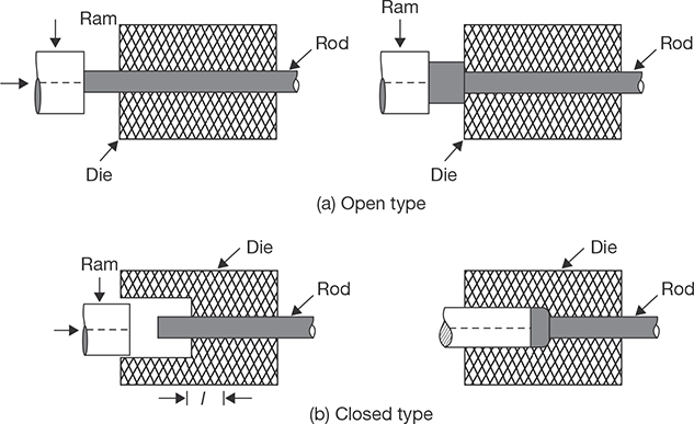
Upset Forging
Upset forging is used to produce head in a bolt, screw, bar, etc. Only a certain portion of the material is deformed and rest is unaffected from the deformation. Upset forging generally employs split dies that contain multiple positions or cavities and may be opened and closed type. The heated bar or rod is positioned in the die and clamped. A hydraulic ram moves longitudinally against the bar, upsetting it into the die cavity.
In open upset forging, the unsupported length (l) of the rod does not exceed 3d to prevent its buckling, ‘d’ being rod diameter. If l > 3d, then closed upset forging is preferred with die diameter, D ≤ 1.5d.
Advantages
- It has better forging quality than obtained by drop forging.
- There is very little flash.
- It has cheaper maintenance and higher productivity.
- The upsetting process can be automated.
Disadvantages
- It is not suitable for forging of the heavier job.
- The maximum diameter of the stock which can be upsetting is limited (about 25cm).
- Intricate nonsymmetrical and heavy jobs are difficult to be forged by this process.
- It has high tooling cost.
Defects in Forging and its Remedies
- Cold Shuts or Laps: It is short cracks at the corners and at right angles to the surface. It is caused by metal surface folding against itself during forging. Sharp corners in dies can result in hindered metal flow which can produce laps. It can be eliminated by proper design of die; the crack on the surface is removed by machining or grinding.
- Pitting: Pitting of the forging surface is caused by scale, which if not removed thoroughly from the die cavity is worked into the surface of forging. When this scale is cleaned from the forging depression remains which are known as ‘Scale pits’. Pitting may be avoided as much as possible during manufacture of forging by proper control of furnace and frequent cleaning of dies.
- Die Shift: Die shift is caused by misalignment between the top and bottom forging dies. This may be caused due to loose wedges.
- Incomplete filling dies: This defect may occur due to an insufficient number of blows during forging, the wrong amount of metal, forging at too low-temperature, poor forging and die design, etc.
- Burnt and Overheated Metal: This defect is caused by improper heating conditions and soaking the metal too long.
- Fins: Fins are small projections or loose metal driven into the surface of the forging.
- Ruptured Fiber Structure: This is a discontinuity in the flow lines of the forging which is revealed only when observing the microstructure. This defect is caused by working some of the alloys too rapidly during the forging operation, inadequate stock size or improper die design.
- Cracks: It occurs on the forging surface which may be longitudinal or transverse. Their occurrence may be due to the poor quality of ingot, improper heating, forging at lowtemperature or incorrect cooling of alloy steel forging.
- Decarburization: If the raw stock is subjected to high-temperature for too long period. It can produce decarburized surface on the forgings, particularly in high carbon steels.
21.4 EXTRUSION
Extrusion is a primary shaping process in which a metal kept in a cylinder is forced to pass through the opening of a die. The metal is subjected to plastic deformation and it undergoes reduction and elongation during extrusion.
There are two types of extrusion—hot extrusion and cold extrusion.
21.4.1 Hot Extrusion
In a hot extrusion the metal billet is heated up to a plastic state and put into a cylinder and it is forced to flow through the opening of a die. On the basis of the direction of flow of the metal with respect to the direction of the force applied hot extrusion is divided into two classes: forward extrusion and backward extrusion.
In forward extrusion, plunger moves in a forward direction and the metal is forced through the die opening in the same direction but in the backward direction, metal forced through the die opening in plunger itself in the backward direction as shown in Figure 21.6.
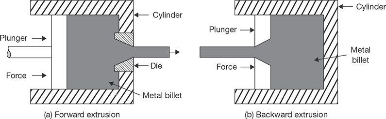
FIGURE 21.6
Forward and Backward Extrusion
Backward hot extrusion involves no friction between the metal billet and chamber walls because the billet does not move in the chamber compared with the forward hot extrusion. Total force required due to low friction in the backward extrusion is less but equipment used is more mechanically complicated in order to accommodate the passage of the extruded shape through the center of the plunger.
21.4.2 Cold Extrusion
Cold extrusion is carried out at room temperature. Because of the large forces required in extrusion, most metals are extruded hot where the deformation resistance of a metal is low. At the same time strain hardening is also eliminated in hot extrusion.
21.4.3 Impact Extrusion
It is essentially a cold process which is mostly used for making collapsible medicine tubes, toothpaste tubes, shaving cream tubes and food canes from more ductile metals such as zinc, lead, tin, aluminum, copper, etc. During the process, the billet is placed in a die cavity and is given a strong single blow through the punch which causes the metal to flow plastically around the punch. The tube thickness is controlled by the clearance between the die and punch. Impact extrusions are low in cost and have an excellent surface finish.
Advantages of Extrusion Process
- The surface finish of the product is quite smooth with relatively close tolerance.
- High production rate since it is a very rapid process.
- A very dense structure of the metal is obtained because of high-pressure used and compressive nature of the process.
- It is an ideal process for producing parts of uniform cross section in large quantities.
- Cheaper than pressure die casting.
(Extrusion ratio, R for Steel = 40:1, and for Aluminum = 400:1)
Where,
 ri = radius of billet, rf = radius of extruded part.
21.5 WIRE DRAWING
Wire drawing is a process to produce a small diameter wire from billet by applying tensile force. A leading end of a wire to be drawn is pointed in a rotary-swaging machine or by some other means. The point is then inserted into the die; and the wire point is properly gripped and pulled sufficiently by a suitable means so that the end can be attached to the power real as shown in Figure 21.7. Then the power reel rotates at the proper speed and pulls the entire piece through the die opening which actually contacts the workpiece, is a smoothly surfaced, truncated, conical opening in a material of the opening is never in contact with the wire being drawn but is filled with lubricant.
The die angle depends upon the metal to be drawn including its hardness from previous cold working and the reduction of area to be affected. A die angle of about 12° is average for the drawing of steels with carbide. Two lubricant methods are currently employed. The mechanism of wire drawing is shown in Figure 21.8. In one method, the wire surface is cleaned, coated with lime, and this is thoroughly dried. Before, entering the die lubricant such as a grease or soap is applied to this surface. The dried lime coating helps to hold this lubricant to the surface as it passes through the die. In the other method, the surface of the wire is first coated with copper or tin. Then, as the metal enters the die, a water carried lubricant is applied. This method is more suitable for final drafts of fine wire.
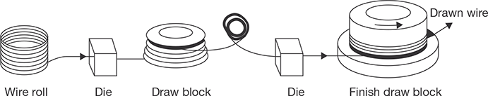
FIGURE 21.7
Wire Drawing Process
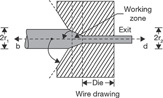
FIGURE 21.8
Mechanism of Wire Drawing
Considerable heat is generated during a wire drawing operation, and water may be circulated around the die to cool it. When the metal of the wire has reached its work hardening limit, annealing is necessary before additional drawing can be done.
21.6 BAR DRAWING
An important difference between the bar drawing and wire drawing is that the bars must remain straight. The length of the bar which can be drawn is limited by the maximum travel of the carriage, which may be from 50 to 100 feet. The first operation, preliminary to drawing is the pointing of the bars by rotary swaging or hammer. After the pointed end is inserted into the die and gripped by the jaws of the carriage, the hook is lowered to engage the moving chain.
21.7 TUBE DRAWING
Like bar drawing, tube drawing is accomplished in most cases with the use of draw bench. Fixed mandrel (Figure 21.9 (a) is most commonly used to control the tube’s internal diameter; Figure 21.9 (b) uses floating mandrel which adjusts itself to the correct position because of its stepped contour; cylindrical mandrel (Figure 21.9 (c) is usually used for small sized tubing, and Figure 21.9 (d), which uses no mandrel or rod and has no control over inside diameter. By repeated cold drawing and annealing when necessary it is possible to reduce a 2-inch diameter to the size of hypodermic needle, which has an outside diameter of about 0.008 inch.
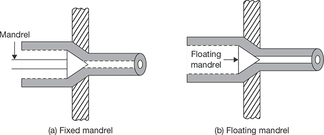
FIGURE 21.9
Tube Drawing Processes
(a) Fixed Mandrel; (b) Floating Mandrel

21.8 HIGH ENERGY RATE FORMING
If the rate of energy flow for forming is high, it is known as high energy rate forming. Energy used may be chemical, magnetic and electro discharge, etc. In high energy rate forming, operation is performed in very less time. Explosive forming, electro-hydraulic forming, and electromagnetic forming are the examples of high energy rate forming.
21.8.1 Explosive Forming
In the explosive forming (Figure 21.10), a shock wave is generated in a fluid medium by detonating an explosive charge. The entire wavefront is utilized in a confined space. But, for the large object, the wavefront may be used for unconfined space and it is less effective than confined space. The typical explosives include TNT and dynamite for higher energy and gun powder for lower energy. With high explosives placed directly over the workpiece, pressure up to 35 kN/mm2 can be generated. With low explosives, the pressure is limited to 350 N/mm2.
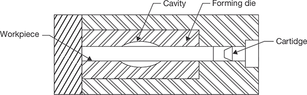
FIGURE 21.10
Explosive Forming
21.8.2 Electrohydraulic Forming
Electric discharge in the form of sparks in the place of explosives can also be used to generate a shock wave in a fluid. An operation using the principle of generating a shock wave is called electro-hydraulic forming. The characteristics of this process are very similar to those of explosive forming. The capacitor bank is charged through the charging circuit; subsequently, the switch is closed resulting in a spark within the electrode gap to discharge the capacitors. The energy level in this process is lower than in explosive forming. The peak pressure developed over the workpiece is a function of the amount of energy discharged (through the spark) and the standoff distance.
21.8.3 Electromagnetic Forming
Just as in electro-hydraulic forming, the electrical energy is first stored in a capacitor bank. This energy is then discharged through a coil by closing the switch. The coil produces a magnetic field, the intensity of this field depends on the value of the current. Since the metallic workpiece is in this magnetic field, a current is induced in the job which sets up its own magnetic field. The directions of these fields are such that the rigidly held coil repels the workpiece into the die. The workpiece obviously has to be electrically conductive but need not be magnetic. The short life of the coil is the major problem in such an operation.
21.9 THREAD ROLLING
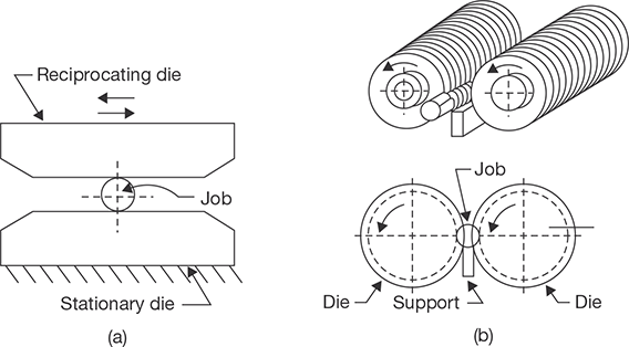
In thread rolling there is no chips formation, i.e., the threads are produced by plastic deformation. Two types of machines are used, namely reciprocating flat die machine and rotating cylindrical die machine.
In a flat die method (Figure 21.11 (a) the cylindrical blanks are automatically fed from a hopper and placed upon a stationary flat hardened steel die plate. Another flat hardened steel die plate which reciprocates and advances and rolls the blank along between them until the thread is complete.
The rotating cylindrical die method (Figure 21.11 (b) may involve either two or three cylindrical dies having a negative impression of the threads. These dies are rotated together on parallel axes, which may be horizontal or vertical. If two cylindrical dies are used, the shafts are normally horizontal and sufficient additional support for the blank between them must be provided. After the blank has been placed on the support, two rotating dies move toward each other to impress the thread on the rotating blank. Cylindrical die machines are more suitable for larger threads, over 3/8 inch outside diameter.
Advantages
- They are cheaper in sufficiently large quantities.
- They are stronger on a result of the cold working and favorable fiber flow line positioning.
Limitations
- It is not suitable for producing internal threads.
- It involves excessive costs in smaller quantities.
21.10 PIERCING OR SEAMLESS TUBING
It is a method to produce seamless tubes. The piercing machine consists of two taper rolls and a cylindrical hot billet passed between these rolls over a mandrel as shown in Figure 21.12. Both the rolls revolve in the same direction and the billet is center punched. The hot billet is pushed forward into the rolls. The rolls grip the billet and pull it. The axes of rolls are crossed at 10°–12° so that they revolve the billet as well as draw it in forward direction and force onto the mandrel. The mandrel can also revolve in its own position. The combination of the revolving motion of the billet and mandrel together with the axial advancement of the billet provides a helical roiling effect of the billet material over the mandrel. If a tube of the larger bore is required, a second piercing operation is required after the completion of the first piercing operation.

FIGURE 21.12
Piercing or Seamless Tubing
21.11 SOME OTHER FORMING PROCESSES
Trimming: The excess metal which remains around parting lines or around other edges after previous operations, such as forging, die-casting and drawing of sheet metal parts is removed by “trimming”. Trimming die is similar to blanking die and the parts are forced through the die by a suitable punch.
Shaving: A very small amount of metal (about 10% of the metal thickness) is removed or “shaved” from blanked or pierced edge in order to obtain edges which are smooth, square, and within closer dimensional tolerances. The parts to be shaved are placed in a locating recess above the die opening and during the downward stroke of the punch, the edge is shaved as the part is forced through the die.
Notching: Notching is the cutting of relatively small indentations in the edge of workpieces. A rubber, used for only small quantities of workpieces, is designed to remove, by a notching action, some metal from an edge of a workpiece.
Embossing: The production of raised or projected designs is relief on a surface is known as “embossing” sheet metal may be embossed between two matching die halves and the operation consists of a combination of drawing and stretching.
Coining: Coining consists of placing a proper amount of metal within a confined de space and exerting sufficient pressure to cause the metal to flow to all properties of the die cavity. The metal is caused to flow in directions perpendicular to the corresponding force along the de surfaces. Since lubrication is not used when good impression details are required, the compressive force required may be enormous.
Peening: This method is employed to set up a superficial state of surface compressive stress, causing the interior of the member to assume an opposite tensile stress. Because fatigue generally occurs from surface cyclically loaded in tension, the useful lives of such member are frequently extended by shot peening.
Hobbing: It is a method of making moulds for the plastic and die casting industries. A punch from tool steel to the shape of the cavity, heat treated for hardness, and polished. It is then pressed into a blank of soft steel method is that one hob properly applied can make a number of cavities in one mould or in a series of mould.
SHEET METAL PROCESS
21.12 INTRODUCTION
Sheet metal is thin and flat pieces of metals. It is one of the fundamental forms used in the metal working, and can be cut and bent into a variety of different shapes. Countless everyday objects are constructed of the material. Thicknesses can vary significantly, although extremely thin thicknesses are considered as foil or leaf, and pieces thicker than 6 mm (0.25 inch) are considered plate. In this text, we will discuss the basic operations in sheet metal.
21.13 SHEET METAL JOINTS
Figure 21.13 shows the common types of sheet metal joints.
Lap Joint: It is the simplest and common type of joint that can be prepared by means of soldering or riveting processes.
Seam Joint: A seam is a joint made by fastening two edges to each other.
Hem Joint: Hem is an edge or border made by folding. It stiffens the sheet and does away with the sharp edge. Generally, two types of Hem joint—single hem and double hem are there. Single Hem joints are made by folding the edges of the sheet over once to make it smooth and stiff while the double hem is made by folding the edges over twice to make it smooth and stiff.
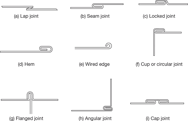
FIGURE 21.13
Sheet Metal Joints
Wired Edge: The wired edge is smooth and very strong as it is prepared by folding the edges along a piece of wire.
Flange Joint: It is commonly used in making pipe connection.
Angular and Cup Joint: Angular and cup joints are mainly used for joining two pieces at an angle of 90o.
Cap Joint: It is a useful form of locked-seam. Soldering or riveting or both processes are generally used with this type of joint to make it more effective in the practical field.
21.14 MATERIALS USED FOR SHEET METAL
The sheet of black iron, tin, galvanized iron (GI), stainless steel, copper, zinc, and aluminum, etc., are widely used in tin smithy work. The sheets are specified by gauge numbers. The larger the gauge number, the lesser the thickness.
Black Iron Sheet: It is the cheapest type of metallic sheet. It has a bluish-black appearance and is often referred to as uncoated sheet. The use of this sheet is limited to articles that are to be painted after fabrication work such as tanks, stoves, and pipes.
Galvanized Iron (GI) Sheet: The zinc coating resists rust and improves the appearance of the metal and permits it to be soldered easily. Welding work on this sheet is not so easy as zinc gives toxic fumes and residues. As it is coated with zinc, galvanized iron sheet withstands contact with water and exposure to weather. It is mainly used to make the articles such as furnaces, cabinets, buckets, pans, and gutters, etc.
Tin Sheet: This is an iron sheet coated with the tin to protect it against rust. This is specially used for soldering work as it is the easiest metal to join by a soldering process. It has the very bright silvery appearance and is used mainly in making of roofs, canes, pans, dairy equipment, and food containers, etc.
Stainless Steel Sheet: Stainless steel sheet used in tin smithy shop can be worked as galvanized iron sheet, but is tougher than galvanized iron sheet. Stainless steel is an alloy of steel with chromium and nickel. It has good corrosive resistance and can be welded easily. It is costly metal. This type of sheet is used in food processing items, chemical plants, canneries, dairies items and kitchen wares, etc.
Copper Sheet: This type of sheet has a better appearance than other metals. The cost of copper sheet is higher in comparison to Galvanized iron sheet. Being resistant to corrosion, it is used for making the articles such as hoods, roof flashing, expansion joints and gutters, etc.
Aluminum Sheet: Aluminum cannot be used in pure form, but is used with a small amount of silicon, manganese, copper and iron. It is highly resistant to corrosion and abrasion, whitish in color and light in weight. It is now widely used in the manufacturing of a number of articles such as trays, refrigerators, household appliances, lighting fixtures, parts of airplanes, electrical and transport industries and in the fitting and fixture used in windows, doors and building requirements, etc.
21.15 HAND TOOLS USED IN SHEET METAL WORK
Steel Rule
It is particularly useful in measuring and laying out small size of work. It is shown in Figure 21.14.
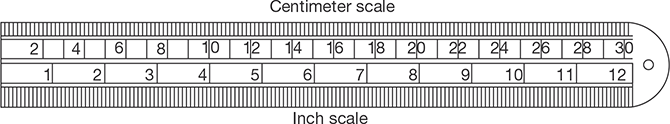
FIGURE 21.14
Steel Rule
Steel Square
This is L-shaped hardened steel piece. It has two parts:
- Tongue
- Body
The narrow arm of the square is known as tongue while the wider part is called as the body as shown in Figure 21.14. It is used for checking the 90° between two adjacent surfaces and for making the line in a perpendicular direction to any baseline.
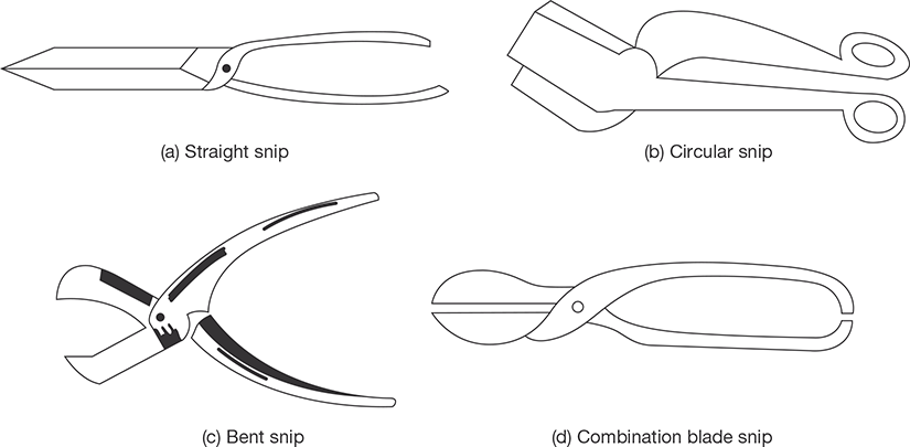
Snips
These are made of high carbon steel and used for cutting thin and soft metallic sheets. There are different types of snips (Figure 21.15) but straight and curved or bent types of snips are commonly used in practice. The straight snip or shear is used for cutting along a straight line while the curved or bent type of snip is used for cutting the sheet along a curvature. Both these snips are very light and can be easily handled by only one hand. A heavier class of snips is known as bench-strip or bench-shear which is fitted on the bench.
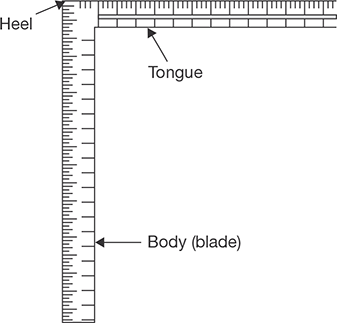
FIGURE 21.14
Steel Square
Punches
These are also made of hardened steel. Punches are used for marking out work and to locate the center in a permanent manner. Punches may be divided into two types:
- Prick Punch or Dot punch
- Center Punch
Prick punch is used to make small marks and to make this prick punch marks larger, we have to use a center punch. Center of the hole that is to be drilled is marked by a center punch.
Dividers
It is made of hardened steel and generally used for drawing or scratching the circles or arcs on the metallic sheet.
Trammel
It consists of a steel bar with two movable steel heads which have bottom part sharply pointed and hardened. The main function of this trammel is to draw large sizes of circles or arcs that are beyond the limit of dividers.
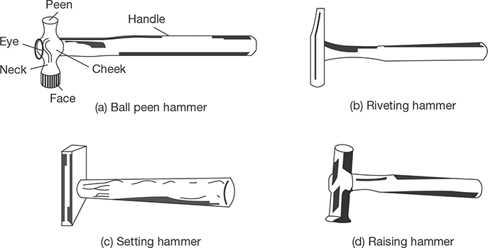
Hammers
To suit the different types of work on the tin sheet, various sizes and shapes of hammers are used (Figure 21.16). They are made to have a square or round heads to suit for striking or hammering the corners and round surfaces respectively. If the peen of the hammer is straight and parallel to axis of hammer (handle), this is known as straight peen hammer; if the peen of the hammer is straight and perpendicular to axis of hammer (handle), this is known as straight peen hammer; and is the peen of the hammer is round, this is known as ball peen hammer. For avoiding the damage of sheet, soft faced hammers are frequently used.
Mallet
This is also used for the striking purpose and made of hard rubber, lead, copper, or mostly of hardwood.
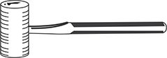
FIGURE 21.17
Mallet
Pliers
These are used for holding and forming the various shapes and patterns (Figure 21.18) In general, flat nose and round nose pliers are widely used.
Slip Gauge or Thickness Gauge
It is also known as slip gauge and is used to measure the clearance between two assembled parts (Figure 21.19).
Sheet Metal Gauge
This is used to measure the thickness of sheets as shown in Figure 21.20.

FIGURE 21.18
Pliers
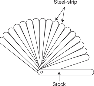

FIGURE 21.20
Sheet Metal Gauge
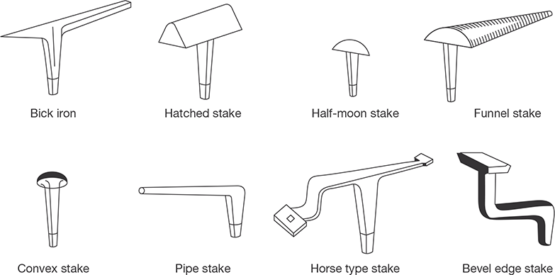
Stakes
Stakes are used for seaming, bending or forming operations. They actually work as supporting tools as well as forming tools. As per nature of work some useful forms of stake are shown in Figure 21.21. In forming operation for long tapered cylindrical items, a bick iron is used while the hatched stake is preferred for forming, seaming and bending the edges. For conical work, a funnel stake is very useful. Half moon stake is very useful for working the edges on discs. For spherical work, a convex stake is preferred. Pipe stake is used for forming tubes. Horse type of stake is used for bending and general work for holding and supporting the other stakes.
21.16 SHEET METAL OPERATIONS
21.16.1 Shearing
It is a general name for a most sheet metal cutting operation in a specific sense. It designates a cut in a straight line across a sheet, bar or strip. It shows clean edges on the metallic job that is to be sheared or cut. Some of the basic shearing operations are described below:
Punching and Blanking
Punching is a process of producing a hole in a flat sheet while blanking is a process of cut out an intricate shape from the sheet which is known as blank (Figure 21.22). The main difference between punching and blanking is that the main ambition in punching holes but in blanking cut out the intricate shape from the sheet. Generally, punching is also called piercing but in piercing the hole is produced in the sheet without removing the metal. There are following points which must be considered during the design of punching and blanking:
- Clearance provided on the die or punch = 10% of the strip thickness.
- In punching, clearance is provided on the die while in blanking, clearance is provided on the punch.
- The shear angle is provided on die in blanking, and on punch in punching.
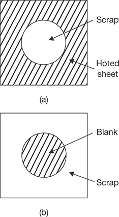
FIGURE 21.22
(a) Punching and (b) Blanking
Perforating: This is a process of punching a number of holes in a sheet.
Parting: This is a process of shearing the sheet into two or more pieces.
Notching: This is a process of removing pieces from the edges.
Lancing: This is a process of leaving a tab without removing any material.
21.16.2 Bending
This is the forming process causes the sheet metal to undergo the desired shape by bending without failure (Figure 21.23).
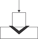
FIGURE 21.23
Bending
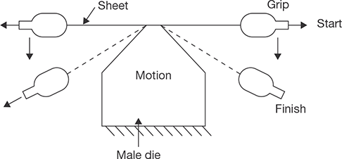
21.16.3 Stretch Forming
In a stretch forming operation, a sheet metal is stretched to yield point in tension and then wrapped over and around the form block (die). This method has the advantage over other forming methods that spring back is either greatly reduced or completely eliminated, since direct bending stress is never introduced. All the plastic deformations occur in the direction of pulling force. Figure 21.24 shows that the jaws grip the work and first stretch and then the wrap it around the die. This method avoids most of the friction which somewhat limits the degree of forming obtainable with the moving die.
21.16.4 Deep Drawing
Deep drawing or drawing is defined as a process of making a cup-shaped part from flat sheet metal blanks. The blank is first heated to provide necessary plasticity for working.
The heated blank is then placed in position over the die or cavity. The punch descends and pushes the metal through the die to form a cup. So this process is also known as cupping (Figure 21.25).
Blank Diameter: If D is the blank diameter in mm, r is the corner radius (in mm), h is the height of the shell as shown in Figure 21.25.
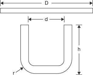
FIGURE 21.25
Cupping or Deep Drawing
Then for thin shells whose wall thickness is t and bottom thickness is T,
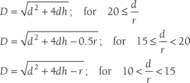
If wall thickness ‘t’ is not equal to bottom thickness ‘T’ which is also the blank thickness.
Since the volume before and after drawing are equal. Therefore, 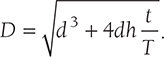
To find a blank diameter for a shell of irregular cross-section equal the weight before and after when a sample is available.
where W − weight of finished shells (grams), w − weight of metal per cubic mm, t − thickness of blank(mm.)
Number of Draws: The number of draws is based on the ration of height and diameter of the cup as shown in the Table 21.1.
Table 21.1: Number of Draws in Deep Drawing

Where, h-depth of the cup, d-shell diameter, D-blank diameter.
Both the factor limit the reduction percentage top limit for the first draw in between 45 and 48% reduction. It is 30% for the second draw and 20% for the third and subsequent draws. The total reduction should not be increased to 70 to 75% when it should be annealed and reduction may again start at the maximum percentage, a number of draws do not exceed 3 to 4 in the way.
21.16.5 Hot Spinning
The parts having circular cross-section can be made by spinning from thin sheet metal. The principle of metal spinning is that a heated circular blank of sheet metal is lightly held against a chuck by the pressure of a freely rotating pad on the lathe tailstock. A rounded stick or roller is pressed against the revolving piece and moved in a series of sweeps as shown in Figure 21.26. This displaces the metal in several steps to conform to the shape of the chuck. Once the operation is started considerable frictional heat is generated which aids in maintaining the metal at a plastic state.
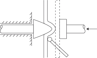
FIGURE 21.26
Hot Spinning

FIGURE 21.27
Eight-roll Sequence for the Roll Forming of a Box Channel
Roll Forming: Roll forming is a process by which a metal strip is progressively bent as it passes through a series of forming rolls.
POWDER METALLURGY
21.17 INTRODUCTION
Powder metallurgy is a process of making components from metallic powders. Initially, it was used to replace castings for metals which were difficult to melt because of high melting point. The development of technique made it possible to produce a product economically, and today it occupies an important place in the field of the metallurgical process. The number of products made by powder metallurgy is increasing including tungsten filaments of lamps, contact points, self-lubricating bearings, and cemented carbides for cutting tools.
The manufacturing of parts by powder metallurgy process involves the following steps:
- Manufacturing of metal powders
- Blending and mixing of powders
- Compacting
- Sintering
- Finishing operations
21.18 MANUFACTURING OF METAL POWDERS
21.18.1 Characteristics of Metal Powder
The performance of metal powders during processing and the properties of powder metallurgy depends on the characteristics of the metal powders that are used. Following are the important characteristics of metal powders: (a) Particle shape, (b) Particle size, (c) Particle size distribution, (d) Flow rate, (e) Compressibility, (f) Apparent density, and (g) Purity.
21.18.2 Methods of Production of the Metal Powders
There are various methods available for the production of powders. Some of the important processes are:
- Atomization
- Machining
- Crushing and Milling
- Reduction
- Electrolytic deposition
- Shotting
- Condensation
Automization: In this method, molten metal is forced through a small orifice and is broken into small particles by a powerful jet of compressed air, inert gas or water jet. These small particles are then allowed to solidify. These are generally spherical in shape. Automation is mostly used for low melting point metals such as brass, bronze, zinc, tin, lead and aluminum, etc.
Machining: In this method, first chips are produced by filing, turning, etc., and then pulverized by crushing and milling. The powders produced by this method are coarse in size and irregular in shape. Hence, this method is used for only special cases such as the production of magnesium powder.
Crushing and Milling: These methods are used for brittle materials. Jaw crushers, stamping mills, ball mills are used to break down the metals by crushing and impact.
Reduction: Pure metal is obtained by reducing its oxide with a suitable reducing gas environment at an elevated temperature (below the melting point) in a controlled furnace. The reduced product is then crushed and milled to a powder. Sponge iron powder is produced this way.
Electrolytic Deposition: This method is specially used to produce iron and copper powders. This is similar to the electroplating process. To produce copper powder, copper plates are placed as anodes in the tank of electrolyte, whereas the aluminum plates are placed into the electrolyte to act as an anode. When D.C. current is passed through the electrolyte, the copper gets deposited on the cathode. The cathode plates are taken out from electrolyte tank and the deposited powder is scraped off. The powder is washed, dried and pulverized to produce a powder of the desired grain size.
Shotting: In this method, the molten metal is poured through a siever or orifice and is cooled by dropping into the water. This produces spherical particles of large size. This method is commonly used for metals of low melting points.
Condensation: In this method, metals are melted and boiled to produce metal vapors and then condensed to obtain metal powders. This process is applied to volatile metals such as zinc, magnesium, and cadmium.
21.19 BLENDING/MIXING OF THE METAL POWDERS
The proper mixing of the powders are essential for uniformity of the product. Lubricants (such as graphite) are added to the blending of powders before mixing. The function of the lubricant is to minimize the wear, to reduce friction. The different types of metal powders are thoroughly mixed in correct proportions in a ball mill, to control the mechanical properties of the products.
21.20 COMPACTING
The main purpose of compacting is converting loose powder into a green compact of accurate shape and size. The adopted for compacting are: pressing, centrifugal compacting, extrusion, gravity sintering, and rolling.
Pressing: The metal powders are placed in a die cavity and compressed to form a component shaped to the contour of the die (Figure 21.28). Mechanical presses are used for compacting objects at low-pressure. Hydraulic presses are for compacting objects at high-pressure.
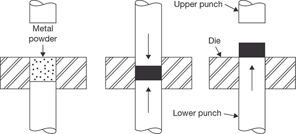
FIGURE 21.28
Compacting (Pressing)
Centrifugal Compacting: In this method, the mold after it is filled with powder is rotated at high speed to get a compact of high and uniform density at a pressure of 3 MPa due to centrifugal force. This method is normally employed for heavy metals such as tungsten carbide.
Extrusion: This method is employed to produce the components with high density. Both cold and hot extrusion processes can be used. In cold extrusion, the metal powder is mixed with a binder and then this mixture is compressed in the form of a billet. The binder is removed before or during sintering. The billet is charged into a container and then forced through the die by means of a ram. The cold extrusion process is used for cemented carbide tools.
In the hot extrusion, the powder is compacted into a billet and is heated to extruding temperature in the non-oxidizing atmosphere. The billet is placed in the container and extruded through a die. This method is used for refractive Barium and nuclear solid materials.
Gravity Sintering: This process is used for making sheets for controlled porosity. In this process, the powder is poured on a ceramic tray to form a uniform layer and is then sintered up to 48 hours in ammonia gas at high-temperature. The sheets are then rolled to desired thickness. The porous sheet of stainless steel is made by this process and popularly used for filters.
Rolling: This method is used for making strips and rods having controlled porosity with uniform mechanical properties. In this method, the metal powder is fed between two rolls which compress and interlock the powder particles to form a sheet of sufficient strength. The metals that can be rolled are Copper, Brass, Bronze, Nickel, Stainless steel and Monel.
21.21 SINTERING
Sintering involves heating of the green compact at high-temperatures in a controlled atmosphere to protect from the oxidation of metal powders. Sintering increases the bond strength between the particles. Sintering temperature is usually 0.6 to 0.8 times the melting point of the powder. In the case of mixed powders of different melting temperature, the sintering temperature will usually be above the melting point of one of the minor constituent.
21.22 FINISHING OPERATIONS
These are secondary operations intended to provide dimensional tolerances, and better surface finish. They are—sizing, coining, machining, impregnation, infiltration, heat treatment, and plating.
Sizing: It is repressing the sintered component in the die to achieve the required size with accuracy.
Coining: It is repressing the sintered components in the die to increase density and to give additional strength.
Machining: Machining operation is carried out on sintered part to provide undercuts, holes, threads, etc., which cannot be removed on the part in the powder metallurgy process.
Impregnation: It is filling with oil, grease, or other lubricants in a sintered component such as bearing.
Infiltration: It is filling of pores of sintered product with molten metal to improve physical properties.
Heat Treatment: The processes of heating and cooling sintered parts are used to improve wear resistance, grain structure, and strength of the product.
21.23 ADVANTAGES OF POWDER METALLURGY
- There is a minimum loss of material.
- The components produced are clean, bright and ready for use.
- The composition of the product can be easily controlled.
- Components can be produced with good surface finish and close tolerance.
- Production rate is high.
- Complex shapes can be produced.
- A wide range of properties such as density, porosity and particle size can be controlled for a specific application.
- There is usually no need for subsequent machining or finishing operations.
- This process facilitates mixing of both metallic and non-metallic powders to give products of special characteristics.
- Porous parts can be produced that could not be made any other process.
- Less skilled labor can be employed.
21.24 LIMITATIONS OF POWDER METALLURGY
- The metal powders and the equipment are very costly.
- Storing of powders offer great difficulties because of the possibility of fire and explosion hazards.
- Parts manufactured by this process have poor ductility.
- Sintering of low melting point powders like lead, zinc, tin, etc., is very difficult.
21.25 APPLICATIONS OF POWDER METALLURGY
Powder metallurgy techniques are applied in the manufacturing of a different kind of products. Some of them are mentioned below as:
- Self-Lubricating Bearing and Filters
- Friction materials
- Gears and Pump Rotors
- Refractory materials
- Electrical contacts and Electrodes
- Magnetic materials
- Cemented carbides
SMITHY
21.26 INTRODUCTION
Smithy is a workplace where metal is worked with heating and hammering. A smithy’s work is concerned with the heating of a metal stock to the desired temperature and enables it to obtain sufficient plasticity so that it can be given the desired shape by the operations like hammering, bending, pressing, etc.
These operations can either be carried out by hand hammering or power hammers. Hand hammering is the process in which forging is done by hand tools. Similarly, forging done with the help of power hammers is known as power forging. Applying pressure for deforming the metal for the required shapes, the primary requirement is to heat the metal to a definite temperature to bring it into the plastic state. This may be done either in an open hearth, known as Smith’s forge or in the closed furnace, i.e., electric furnace or oil furnace. Smaller jobs are normally heated in the Smith’s forge and larger jobs in closed furnaces. The hand forging process is employed for relatively smaller components and the power or machine forging is used for larger jobs requiring very heavy blows and drop forging for mass production of identical parts.
21.27 MAJOR TOOLS USED IN SMITHY SHOP
21.27.1 Smith’s Forge or Hearth
It has a robust cast iron structure having four legs support, an iron bottom known as hearth, a hood at the top and tuyere opening into the hearth either from the rear or from the bottom as shown in the Figure 21.29. The hearth carries the coal and provided with bricks lining. Air, under pressure, is supplied through the tuyere opening in the hearth with the help of a blower. At suitable points, auxiliary pipes are used to connect the tuyere with the main pipeline. A valve is incorporated in the auxiliary pipe, just before the place where it is connected with the tuyere, to control the supply of air to the furnace. The chimney provided at the top to escape of smoke and gases produced due to the burning of coal. A water tank is provided, in front of the forge, which carries water for the purpose of quenching. The metal block is heated in at the coal bed up to plastic state before forging.
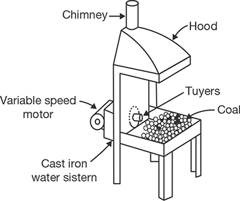
FIGURE 21.29
Smith’s Forge or Hearth
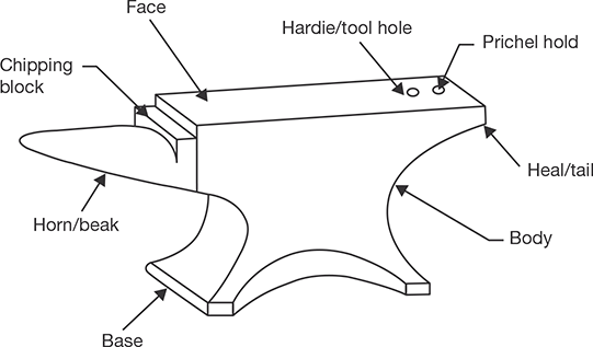
21.27.2 Anvil
Anvil is a type of rigid support to the job to be forged or hammered. It has the capability to bear heavy blows rendered to the job as shown in the Figure 21.30. It is made of cast iron/wrought iron with a hardened top about 20 to 25 mm thick. It consists of a horn/ beak, which is used to provide bend or curved shapes to the job. A flat step between the top and beak is provided to support the job during cutting and is known as chipping block. The flat projecting part of the back of the anvil is known as the tail. It carries a square hole to accommodate the square shank of the bottom part of various hand tools like swages, fuller. It is called a hardie hole. The circular hole provided near the hardie hole is known as pritchel hole. The top face of the anvil should stand at about 0.75 m from the floor. However, anvil may be of different weight and sizes depending on its applications.
21.27.3 Hammer
Hammers are used to blow the job by striking on it. The hammer is classified according to its shape and weight. The heavy hammer in a larger size is known as sledge hammer and used by a separate person, known as hammer man. The lighter in weight and small size hammers, i.e., Smith’s hammers are also classified into ball peen hammer, cross peen hammer, and straight peen hammer. The different parts of the hammer are shown in the Figure 21.31.
In ball peen hammer, the shape of the peen is spherical; in cross peen hammer the shape of the peen is linear but perpendicular to the axis and in straight peen hammer, the peen is linear but parallel to the axis. All the hammers are mainly divided into four parts; namely peen, eye, cheeks, and face. The peen is the top part made slightly tapered from the cheeks and rounded at the top. Just below the peen, the part is known as the neck. The face is hardened and polished well and is given slight rounding along the circular edges so that the metal surface is not spoiled by the sharp edges when the former is struck by the hammer. The eye is normally made oval or elliptical in shape and accommodates the handle. For small sized hammers these handles are made of wood or bamboo, but in the case of sledge hammers, the handles made of solid bamboos. An arrangement of the wedge is done in the handle so that slipping of the hammer off the handle during striking can be avoided. Sledge hammers are comparatively 3 to 4 times heavier than the hand hammers. They are available in varying sizes and weights from 3 to 8 kg. They are employed when heavy blows are needed in forging and other operations done on heavy jobs.

21.27.4 Swage Block
Swage block is made of cast iron having a number of slots of different shapes and sizes along its four side faces and through holes from its top face to bottom face as shown in the Figure 21.32.
It is used as a support in punching holes and forming different shapes. The job to be given a required shape is kept on a similar shaped slot, which acts as a bottom swage, and then the top swage is applied on the other side of the job. Swages consist of two parts: the top part having handle and a bottom part having a square shank, which fits in the hardie hole in the anvil. The holes in the top and bottom face are used in punching. Their use prevents the punch from spoiling by striking against a hard surface after the hole has been punched.

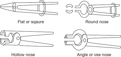
FIGURE 21.33
Tongs
21.27.5 Tongs
Tongs are used to hold the jobs in a specific position and turning over during forging. They are made of mild steel. Tongs are made of mild steel generally in two pieces, which are riveted together to form a hinge as shown in the Figure 21.33. Smaller length on one side of the hinge consists of the holding jaws, which are made of different shapes and sizes to hold the jobs of various shapes and sizes, and the longer portions on the other side of the hinge form the arms, which are held in hand by the smith to apply the pressure on the job through the jaws. Tongs may be made of different shapes and size to handle the different shapes of the jobs, but the commonly used lengths of the tongs in hand forging vary from 400 to 600 mm with the jaws’ opening ranging from 6 to 55 mm. The nomenclature of the tongs is based on the shapes of the jaws, e.g., flat or square tong, round tong, hollow nose tong, the angle of vee nose tong, etc.
21.27.6 Chisels
Chisels are used to cut metals in the hot or cold state. The chisels which are used for cutting the metal in hot state are termed as hot chisels and the others used for cutting in cold state are known as cold chisels as shown in the Figure 21.34. A cold chisel carries an included angle of 60° at the cutting edge and the latter is well hardened and tempered. It is made of high carbon steel. A hot chisel can be made of medium carbon steel as there is no need of hardening. It is used to cut the metal in a plastic state. The included angle of its cutting edge is 30°.
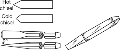
FIGURE 21.34
Chisel
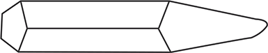
21.27.7 Punches
Punches are used to produce holes in red hot jobs as shown in the Figure 21.35. They are tapered tools made in various shapes and sizes. A larger tapered punch is called a drift. The job is placed on the anvil and the punch is hammered through it up to about half its depth. It is then turned over and the punch made to pass through it. Completion of this operation in two stages prevents the job from splitting and full to bursting.
21.27.8 Flatters
Flatters are made of high carbon steel. They are used to give smoothness and accuracy to articles, which have already been shaped by fullers and swages. These are also known as smoothers. They consist of a square body, fitted with a handle, and a flat square bottom as shown in the Figure 21.36. They are used for leveling and finishing a flat surface after drawing out or any other forging operation.
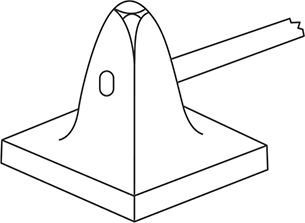
FIGURE 21.36
Flatter
21.27.9 Set Hammer
Set hammer is used to finish the corners of the jobs, formed by two adjacent surfaces at right angles as shown in the Figure 21.37. The job is supported on the anvil and the tool is hammered from the top. It is a type of hammer, but not used for hammering or blowing purposes. It is made of tool steel and hardened. Its construction is also similar to that of a flatter but is smaller in size and it does not carry an enlarged bottom face.
21.27.10 Fullers
Fullers are used to produce a neck in the jobs. They are made in the top and bottom tools as shown in the Figure 21.38. Fullers are made in various shapes and sizes according to needs, the size denoting the width of the fuller. These tools are made of high carbon steel in different sizes to suit the various types of jobs. They are generally used in pairs, consisting of a top and bottom filler. Their working edges are normally rounded.
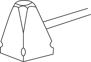
FIGURE 21.37
Set Hammer
FIGURE 21.38
Fullers

FIGURE 21.39
Swages
21.27.11 Swages
Swages are very similar to fullers made of high steel in two parts called the top and bottom swage, but their faces carry circular grooves to suit the size of the work as shown in the Figure 21.39. The top swage carries a handle and the bottom swage carries a square shank, which is fitted in the hardie hole of the anvil during the operation.
RECAP ZONE
Points to Remember
- Mechanical working is a process of shaping of metals by plastic deformation.
- When metal is deformed between room temperature and recrystallization temperature, it is called cold working.
- When metal is deformed between recrystallization temperature and a melting point of the metal, it is called hot working.
- The recrystallization temperature is defined as “the approximate minimum temperature at which the complete recrystallization of cold worked metal occurs within a specified period of time.
- Rolling is the process of reducing the thickness or changing the cross-sectional area of the workpiece by means of rolling mills.
- Forging is a process of plastic deformation for shaping. The force applied in this case is an intermittently compressive force while in a rolling process force applied is a continuous compressive force.
- In open die forging, the hot workpiece is placed between two flat dies and is hammered to produce the desired shape.
- In impression-die forging the heated workpiece is placed between two required shaped die and is pressed or hammered.
- Closed die-forging is a variation of impression-die forging without flash.
- In drop forging, the metal is deformed by the impact of a hammer or die and hot metal is forced to confirm the die shape.
- Press forging employs a slow squeezing action produced by mechanically or hydraulically operated press as compared to rapid impact blows of hammer in drop forging.
- Upset forging is used to produce head in a bolt, screw, bar, etc. Only a certain portion of the material is deformed and rest is unaffected from the deformation.
- Extrusion is a primary shaping process in which a metal kept in a cylinder is forced to pass through the opening of a die.
- Wire drawing is a process to produce a small diameter wire from billet by applying tensile force.
- An important difference between the bar drawing and wire drawing is that the bars must remain straight. The length of the bar which can be drawn is limited by the maximum travel of the carriage, which may be from 50 to 100 feet.
- Like bar drawing, tube drawing is accomplished in most cases with the use of draw bench.
- If the rate of energy flow for forming is high, it is known as high energy rate forming. Energy used may be chemical, magnetic, and electro discharge, etc.
- In thread rolling there is no chips formation, i.e., the threads are produced by plastic deformation.
- Sheet metal is thin and flat pieces of metals. It is one of the fundamental forms used in metalworking and can be cut and bent into a variety of different shapes.
- Punching is a process of producing a hole in a flat sheet while blanking is a process of cut out an intricate shape from the sheet which is known as blank.
- In a stretch forming operation, a sheet metal is stretched to yield point in tension and then wrapped over and around the form block (die).
- Deep drawing or drawing is defined as a process of making the cup-shaped parts from flat sheet metal blanks.
- Powder metallurgy is a process of making components from metallic powders.
- Smithy is a workplace where metal is worked with heating and hammering.
- A smithy’s work is concerned with the heating of a metal stock to a desired temperature and enables it to obtain sufficient plasticity so that it can be given a desired shape by the operations like hammering, bending, pressing, etc.
- Anvil is a type of rigid support to the job to be forged or hammered.
- Hammers are used to blow the job by striking on it. The hammer is classified according to its shape and weight.
- Swage block is used as a support in punching holes and forming different shapes.
- Tongs are used to hold the jobs in a specific position and turning over during forging.
- Chisels are used to cut metals in the hot or cold state.
- Punches are used to produce holes in red hot jobs.
- Fullers are used to give smoothness and accuracy to articles, which have already been shaped by fullers and swages.
- Set hammer is used to finish the corners of the jobs, formed by two adjacent surfaces at right angles.
- Fullers are used to produce a neck in the jobs.
- Swages are very similar to fullers made of high steel in two parts called the top and bottom swage, but their faces carry circular grooves to suit the size of the work.
REVIEW ZONE
Multiple-choice Questions
- The important property of a material in all metal forming process is:
- Elasticity
- Plasticity
- Ductility
- Brittleness
- Which of the following material cannot be forged:
- Wrought iron
- Cast iron
- Mild steel
- High carbon steel
- Mechanical properties of the metal improve in hot working due to:
- Recovery of grains
- Recrystallization
- Grain growth
- Refinement of grain size
- The increase in hardness due to cold working is called:
- Cold hardening
- Hot hardening
- Strain hardening
- Age hardening
- The extruded product moves in the backward direction opposite to that of the deforming force in:
- Forward extrusion
- Die extrusion
- Backward extrusion
- Wire drawing
- Hot working operations are carried at:
- Recrystallization temperature
- Below crystallization temperature
- Above crystallization temperature
- Above room temperature
- Seamless tubes are made by:
- Piercing
- Extrusion
- Rolling
- Plug rolling
- The operation of removing the burr or flash from the forged parts in drop forging is known as:
- Lancing
- Coining
- Trimming
- Shot peening
- In four high rolls mill, the bigger roll is called:
- Guide rolls
- Back up rolls
- Main rolls
- Support rolls
- Large size bolt heads are made by:
- Swaging
- Roll forging
- Tumbling
- Upset forging
- Symmetrical hollow parts of circular cross section are made by hot:
- Forging
- Extrusion
- Piercing
- Spinning
- In drawing operation, the metal flows due to:
- Ductility
- Work hardening
- Plasticity
- Shearing
- Hemming is the operation:
- In which the edges of the sheet are turned over to provide stiffness and a smooth edge.
- Of producing contours in sheet metal and bending previously roll formed sections.
- Employed to expand a tubular or cylindrical part.
- None of these
Fill in the Blanks
- 14. If the rate of energy flow for forming is high, it is known as _____.
- 15. _____ is defined as process for the making of cup shaped parts from flat sheet metal blanks.
- 16. Punching is a process of producing ______ in a flat sheet.
- 17. Powder metallurgy is a process of making components from ______.
- 18. When metal is deformed between recrystallization temperature and melting point of the metal, it is called _______.
- 19. When metal is deformed between room temperature and recrystallization temperature, it is called ______.
- 20. ______is a process to produce a small diameter wire from billet by applying tensile force.
Answers
Theory Questions
- What do you mean by mechanical working? Differentiate between hot working and cold working.
- What is forging? Explain different forging process.
- Explain the various forging defects and its remedies.
- Explain the rolling process and the defects occurred in rolling.
- Differentiate between backward and forward extrusions.
- Write notes on high energy rate forming.
- Explain the process of tube drawing.
- What is the basic difference between bar drawing and wire drawing?
- What do you mean by stretch forming?
- Write the name and applications of different hand tools used in sheet metals.
- What are the various sheet metal operations?
- Differentiate between punching and blanking.
- Explain the process of deep drawing.
- Explain the process to manufacture internal and external threads using forming process.
- What is powder metallurgy? Explain the various steps used in powder metallurgy.
- Explain the methods to produce metal powders.
- Explain the advantages, disadvantages, and applications of powder metallurgy.
- What do you mean by smithy?
- Write short notes on: (i) Hearth, (ii) Anvil, (iii) Set hammers, (iv) Swage blocks, (v) Fullers,(vi) Flatters, and (vii) Swages.