
CHAPTER 5
Steam and Gas Turbines
Learning Objectives
By the end of this chapter, the student will be able:
- To understand the utilization of heat energy of steam and flue gas in producing shaft/mechanical power
- To demonstrate the construction and working of steam and gas turbines
- To solve the design problems of steam and gas turbines
- To describe the principle of working of the Rankine and Jule cycle
5.1 INTRODUCTION
The steam power system is a system in which the heat energy of the steam is used to produce mechanical power. Various types of fuels (coal, diesel, natural gas, geothermal, nuclear, etc.) are used to produce the high quality of steam, i.e., superheated steam and then the thermodynamic expansion process is used to convert the heat energy of the steam into mechanical power. If mechanical power is developed in the form of shaft power and the shaft is coupled with electricity generator then the mechanical power is transformed into electrical energy. The steam engine was developed by James Watt in 1763 after that steam turbines, gas turbines, and I.C. Engines came into the picture.
5.2 STEAM ENGINE AND ITS WORKING PRINCIPLES
A steam engine is a reciprocating heat engine that performs mechanical work using steam as its working fluid. Steam engines are external combustion engines based on modified Rankine cycle, where the working fluid is separate from the combustion products. Water is heated into steam in a boiler until it reaches a high pressure and then expanded through pistons to do some mechanical work. The reduced-pressure steam is then released into the atmosphere or condensed and pumped back into the boiler. The working of steam engine is shown in Figure 5.1.
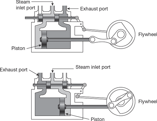
In a steam engine, the movement of the valve ensures that steam is admitted to and exhausted from the cylinder at the right moment. For a typical cylinder that has two ports, i.e., double acting reciprocating steam engine, the function of the valve is to admit superheated steam at one end while allowing the exhaust steam to escape at the other. As a result of covering and uncovering these ports in sequence, the piston is pushed forward and backward by the high-pressure steam from the boiler. To regulate the movement of the valve, a mechanical valve gear system is used.
Lap refers to the amount of overlap between the valve and the port. In slow moving locomotives, the long lap on the exhaust port gives time for the steam trapped in the cylinder to expand fully to push the piston. On the other hand, on higher speed locomotives the exhaust port is made to open early (short lap) when the valve is in mid-position thus allowing the steam to escape faster. Higher speed locomotives also have a long lead, which means that the admission port is already open when the piston is at the end of its movement so there is a sufficient steam pressure that will immediately push the piston back to begin its next movement.
The indicator diagram such as shown in Figure 5.2 was used by steam locomotive engineers during the steam era to estimate the locomotive’s efficiency in converting the steam’s energy into useful power at various speeds and cut-offs. The horizontal line at the top of the indicator diagram shows the pressure as the steam enters the cylinder. At cut-off, the pressure drops as the steam expands and does work to push against the piston. Cut-off denotes the position of the piston, at the moment the valve is closing the admission port. When the engine is working hard and slowly, long cut-off admits steam for most of the stroke of the piston. On fast running locomotives, this will cause back pressure to the boiler. To avoid unnecessary back pressure, the cut-off is reduced so that steam is admitted for only 20% of the piston stroke and the remainder of the stroke is due to the expansion of the highpressure steam.

After the exhaust port opens, the horizontal line at the bottom of the indicator diagram indicates the return stroke of the piston. It shows the low pressure as the steam is exhausted. The curve at the end of the return stroke shows a pressure rise due to the compression of the remaining steam after the exhaust port has closed. As fresh steam is admitted into the cylinder, the pressure rises and the cycle repeats.
5.2.1 Modified Rankine Cycle: Theoretical Indicator Diagram
Theoretical indicator diagram of a steam engine is shown in Figure 5.3 without clearance volume and with clearance volume in Figure 5.4. In this diagram, clearance volume is zero. Steam at boiler pressure enters into the cylinder at the point 1 and cut-off at point 2. Then the steam expands inside the cylinder isothermally from point 2 to point 3. Point 3 represents atmospheric pressure and the exhaust of the steam occurs at point 4, i.e., below the atmospheric pressure. Point 4 is known as the point of release. Exhaust occurs at constant pressure line 4-5. Again, steam enters into the cylinder at point 5 but suddenly the pressure increases to point 1.
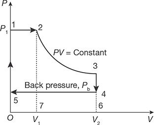
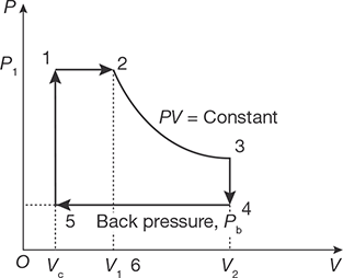
FIGURE 5.4
Theoretical Indicator Diagram of Steam Engine with Clearance Volume
Work done per cycle = Area of 12345
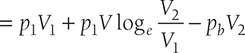
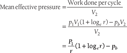
Work done per cycle with clearance volume
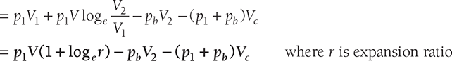
Mean effective pressure with clearance volume
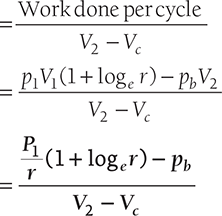
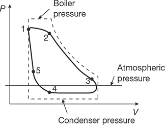
FIGURE 5.5
Actual Indicator Diagram for Steam Engine
Actual Indicator diagram: Actual indicator diagram is shown in Figure 5.5.
In actual indicator diagram (Figure 5.5), points 1, 2, 3, 4, and 5 show actual admission pressure, point of cut-off, point of release, point of closing the exhaust port and starting of compression, and point of opening of admission port respectively.
The area of actual indicator diagram is less than the theoretical indicator diagram.

Indicated power of single acting reciprocating steam engine
Indicated power of double acting reciprocating steam engine
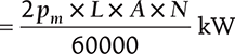
where pm is a mean effective pressure, L is a length of stroke, A is a piston c/s area, and N is rpm.
5.2.2 Rankine Cycle
The Rankine cycle is most commonly used in thermal power plants: steam engine and steam turbines. The Rankine cycle is sometimes referred to as a practical Carnot cycle because, when an efficient turbine is used, the TS diagram begins to resemble the Carnot cycle. The main difference is that heat addition and rejection are at constant pressure in the Rankine cycle and isothermal in the theoretical Carnot cycle. A pump is used to pressurize the water received from the condenser. To pump the working fluid through the cycle as a liquid requires a very small fraction of the energy needed to transport it as compared to compressing the working fluid as a gas in a compressor (as in the Carnot cycle). Carnot efficiency of about 63% compared with an actual efficiency of 42% for a modern coal-fired power station.

The working fluid in a Rankine cycle follows a closed loop and is reused continuously. Work is required to drive the pump, the working fluid is in its liquid phase at this point. By condensing the fluid, the work required by the pump consumes only 1% to 3% of the turbine power and contributes to a much higher efficiency for a real cycle.
Four Processes in the Rankine Cycle
There are four important processes in the Rankine cycle. These states are identified by numbers as shown in Figure 5.6.
Process 1–2 (Pumping Process): The working fluid is pumped from low pressure to high pressure, as the fluid is a liquid at this stage the pump requires some small amount of input energy.
Process 2–3 (Heating Process): The high-pressure liquid enters a boiler where it is heated at constant pressure by an external heat source to become a dry saturated/superheated steam. The input energy required can be easily calculated using mollier diagram or h-s chart or enthalpy-entropy chart also known as steam tables.
Process 3–4 (Expansion Process): The dry saturated or superheated steam expands in the turbine. This decreases the temperature and pressure of the steam, and some condensation may occur. The output in this process can be easily calculated using the Enthalpy-entropy chart or the steam tables.
Process 4–1 (Condensation Process): The wet vapor then enters a condenser where it is condensed at a constant temperature to become a saturated liquid.
The flow diagram of a steam power plant is shown in Figure 5.7
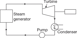
FIGURE 5.7
Flow Diagram of Power Plant
Suppose
Q̇in heat suppliedtowater inturbine
Q̇out Heat librated in condensor
Ẇpump Work done on pump
Ẇturbine Work done by turbine
The thermal efficiency of Rankine cycle can be given as:
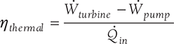
Where Ẇturbine = h3 − h4 ; Ẇ pump = h2 − h1;
Q̇ in = h3 − h2; Q̇out = h4 − h1
5.3 STEAM TURBINES
Steam turbine is a prime mover, which converts the heat energy of steam into mechanical energy by rotating motion of the blade. Total energy conversion involves two types of steam expansion: expansion of steam in the nozzle and expansion of steam in turbine blades. The function of steam engines and steam turbine are similar, but the steam engine converts the heat energy of steam into mechanical energy by the reciprocating motion of the piston whereas in steam turbine the energy conversion takes place due to rotation of the turbine shaft. Steam energy is used for low power generation and efficiency is lesser than that of the steam turbine.
5.3.1 Classification of Steam Turbine
Broadly, steam turbine can be classified into two categories as follows:
- Impulse Turbine
- Impulse-Reaction Turbine
Pure reaction turbine cannot be used for practical purposes; therefore, the impulsereaction turbine is referred as reaction turbine.
Impulse Turbine (de-Laval Turbine)
If torque produced on the shaft of the turbine is only due to change in momentum of steam and pressure of steam at the inlet and outlet of the turbine being same, it is known as impulse turbine. In this turbine, the expansion of high-pressure steam occurs only in the nozzle as shown in Figure 5.8 (a) and (b). During passage of steam through the blade, its direction changes which results in change in momentum equal to impulse on the blade.
Working of Impulse Turbine
In the impulse turbine, all the pressure drops occur in the nozzle and there is no pressure drop of steam passing through the blades. Let us consider steam enters the nozzle with the pressure of P0 and velocity of V0 after expansion of steam in nozzle pressure drops to P1 and velocity increases to V1. High-velocity jets of steam impinge on the blades with velocity V1 gets deflected by an angle and comes out with a smaller velocity V2 producing an impulse on the blades. The pressure P1 remains constant passing through the blades.
Now, momentum at the inlet of the blade – momentum at the exit of the blade = Impulse on the blade absorbed in producing shaft work.
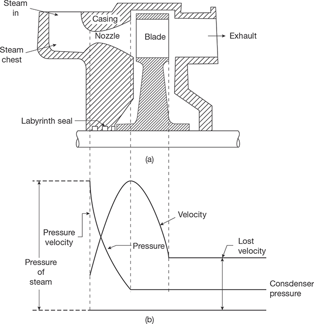
FIGURE 5.8
(a) Impulse Turbine (b) Pressure and Velocity Diagram
After expansion of steam in the nozzle, it strikes the blades with absolute velocity V1 which rotates the blade with mean peripheral velocity u, steam leaves the blade with relative velocity Vr2 and absolute velocity V2 as shown in Figure 5.9.
α = nozzle angle with direction of rotation of wheel
β1 = inlet blade angle
β2 = outlet blade angle
u = peripheral velocity of wheel
Here,
- γ = Exit blade angle
- δ = Angle made by absolute exit velocity of steam leaving the blades with the plane of rotation of wheel
- Vω = Velocity of whirl
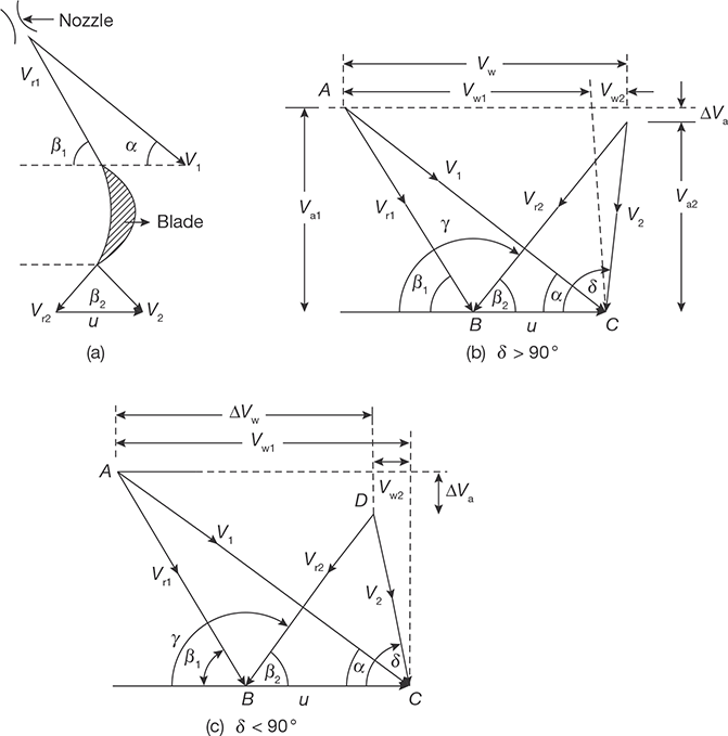
FIGURE 5.9
Velocity Diagram for Impulse Turbine
ΔVω, (change in velocity of whirl) = Vω1 − Vω2 = V1cosα − V2 cosδ
If δ > 900 ; ΔVω = Vω1 + Vω2
If δ < 900; ΔVω = Vω1 − Vω2
In figure 5.9 (b), in ΔABC

In ΔCBD
Similarly, in Figure 3.2(c)
Blade Friction Factor
It is a ratio of the relative velocity of steam at the exit to the relative velocity at the inlet of the blade. It is denoted by Kb
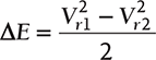
Energy loss due to friction in blade
In terms of Kb, ΔVw = (V1 cosα − u)(1 + Kb ); If blades are symmetrical, i.e., β1 = β2
Tangential Thrust
Axial Thrust
Blade Work or Diagram Work
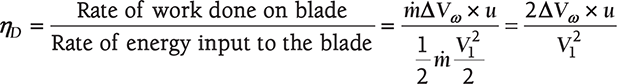
Blade or Diagram Efficiency
Maximum Blade Efficiency and Optimum Velocity Ratio
Substituting ΔVw in equation of blade efficiency as

Velocity ratio is the ratio of mean velocity to the jet velocity

as
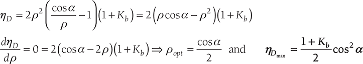
Putting the value of ρ as ![]() and if loss of energy due to friction is zero, i.e., K = 1
and if loss of energy due to friction is zero, i.e., K = 1
Thus, the lower is the nozzle angle, the higher is the blade efficiency. But, too low nozzle angle causes energy loss at the blade inlet. Therefore, the nozzle angle is to be maintained within a certain range which varies from 16° to 22°.
EXAMPLE 5.1
Steam enters is an impulse turbine at 1000 m/s and at a nozzle angle of 18°. The mean peripheral velocity of the blades is 600 m/s and blades are symmetrical. If the steam is to enter the blades without shock, what will be the blade angles?
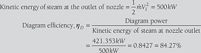
- If the friction effect is negligible on the blades, calculate the tangential thrust on the blades and diagram power for a unit mass flow rate of steam.
- If blade friction (Kb) is 0.8, estimate the axial thrust, diagram power, and diagram efficiency.
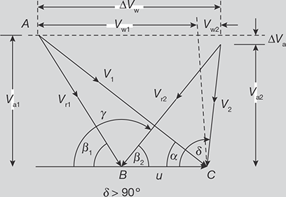
FIGURE 5.10
Velocity Triangle
Velocity triangle is shown in Figure 5.10
V1 = 1000 m/s, α = 180, u = 600 m/s.
Blades are symmetrical, i.e., β1= β2; ṁ = 1 kg/s.

- From Equation (5.1),
Vr1 sin 42.350 = 309.01m /sec or, Vr1 = 467.74m / sec = Vr2ΔVω = Vr1 cosβ1 + Vr2 cosβ2 = 2Vr1 cosβ1= 2 × 467.74 m/sec × 0.7506 = 702.25 m /secΔVα = Vr1 sinβ1 − Vr2 sinβ2 = 0Tangential thrust, Ft = ṁ × ΔVω = 1 kg /sec × 702.25 m/sec = 702.25 NAxial thrust, Fα = ṁ × ΔVα = 0Diagram Power, WD = Ft × u = 702.25 N × 600 m / sec = 421.353 kW
-
Vr2 = 0.8Vr1 = 0.8 × 467.74m / sec = 374.192m / sec; β1 = β2 = 41.350
ΔVω = Vr1 cosβ1 + Vr2 cos β2 = 632.028m / sec
ΔVα = Vr1 sin β1 − Vr2 sin β2 = 61.803m / sec
Tangential thrust, Ft = ṁ × ΔVω = 1kg / sec× 632.028m / sec = 632.028NAxial thrust, Fα = ṁ× ΔVα = 1kg / sec× 61.803m / sec = 61.803NDiagram Power, WD = Ft × u = 632.028N × 600m / sec = 379.216 kW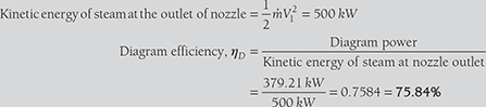
5.3.2 Compounding of Impulse Turbine
Single row of the nozzle with a single row of the blade is called one stage of the turbine. If steam at very high pressure is allowed to expand in a single stage of the turbine, the blade velocity will be too high. Such a high rotational speed cannot be used properly and also there will be velocity loss at the exit of the blade due to high exit velocity of steam. Therefore, to overcome these difficulties, the turbine is compounded or staged. In compounded turbines, steam is made to expand in a number of stages instead of single stage and turbine speed is reduced, which secures the same enthalpy drop of steam. There are three types of compounding of impulse turbine:
- Pressure compounding or Reteau staging
- Velocity compounding or Curtis staging
- Pressure-velocity compounding.
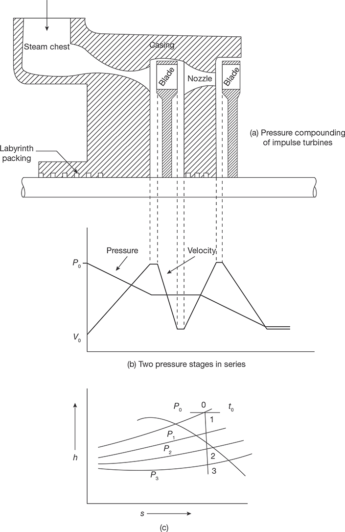
Pressure Compounding or Reteau Staging
Pressure compounding is splitting of whole pressure drops of steam from the steam chest pressure to condenser pressure into a series of small pressure drops across several stages of impulse turbine. The whole pressure drops occur in the series of nozzles and there is no pressure drop in fixed blades as shown in Figure 5.11. The kinetic energy of steam increases in nozzles at the expense of the pressure drops and it is absorbed by the blades in producing a torque on the shaft.
The pressure compounding of the turbine is shown in Figure 5.11 (a) and pressure-velocity diagram in Figure 5.11 (b). The enthalpy drop in one stage is equal to the total enthalpy drop divided by the number of stages as shown in Figure 5.11 (c).
Velocity Compounding or Curtis Stages
In this compounding, whole pressure drop takes place in the nozzle (only one row) and remains constant in fixed and moving blades. The velocity of the steam remains constant in fixed blades and decreases in moving blades.
Figure 5.12 (a) shows a two row Curtis or velocity staging having two rows of moving blades and one row of fixed blades in between them. In three-rows of Curtis stage, the tworow stage is followed by the second row of guide blade and third row of moving blades. Steam of high kinetic energy passing through nozzle impinges on the first row of moving blades and gets deflected by the first row of fixed blades of guide blades. The steam, after a deflection from the first row of fixed blades, impinges on the second row of moving blades and again gets deflected by second row of guide blades. Finally, steam impinges on the third row of moving blades and thus, does work on turbine shaft.
The velocity diagrams for first stage and second stage of moving blades are shown in Figure 5.12 (c) and (d). The blade friction factor Kb may be assumed the same for both mov-ing and fixed blades.
Hence, 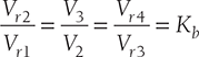
α1 = exit angle of guide blades
β1, β2 = Inlet and exit angles of first row of moving blades
β3, β4 = Inlet and exit angles of second row of moving blades
ΔVω1, ΔVω2 = Change in the velocity component of the whirl in the first and second rows of moving blades
ΔVα1, ΔVα2 = Change in the axial components of velocity in the first and second rows of moving blades
Tangential thrust,![]()
Axial thrust,![]()
Blade work or diagram work, WD = Ft × u
Diagramefficiency, 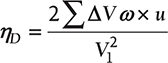
- In two-row curtis stage, 3/4th of the total work is done by steam jets on the first row of moving blades and one-fourth of the total work is done on the second row of moving blades.
- In 3-rows curtis stage, it can be shown that
WD1 : WD2 : WD3 = 5: 3:1
ηDmax = cos2 α
![]() where n is number of stages
where n is number of stages

Pressure-Velocity Compounding
It is a combination of pressure compounding and velocity compounding as shown in Figure 5.13 (a). There are two-rotors and only two rows of moving blades are attached on each rotor because two-row wheels are more efficient than three-row wheels. The steam on passing through each row of moving blades reduces its velocity, but the pressure remains constant during passing through these blades. Thus, it acts as a velocity compounded. The whole pressure drops in two nozzles as shown in Figure 5.13, thus, it acts as a pressure compounded.
5.3.3 Impulses-reaction Turbine (Reaction Turbine)
If steam expands both in the nozzle as well as in blades of a turbine, i.e., pressure at the inlet of the turbine is more than that of the outlet, it is known as an impulse-reaction turbine.
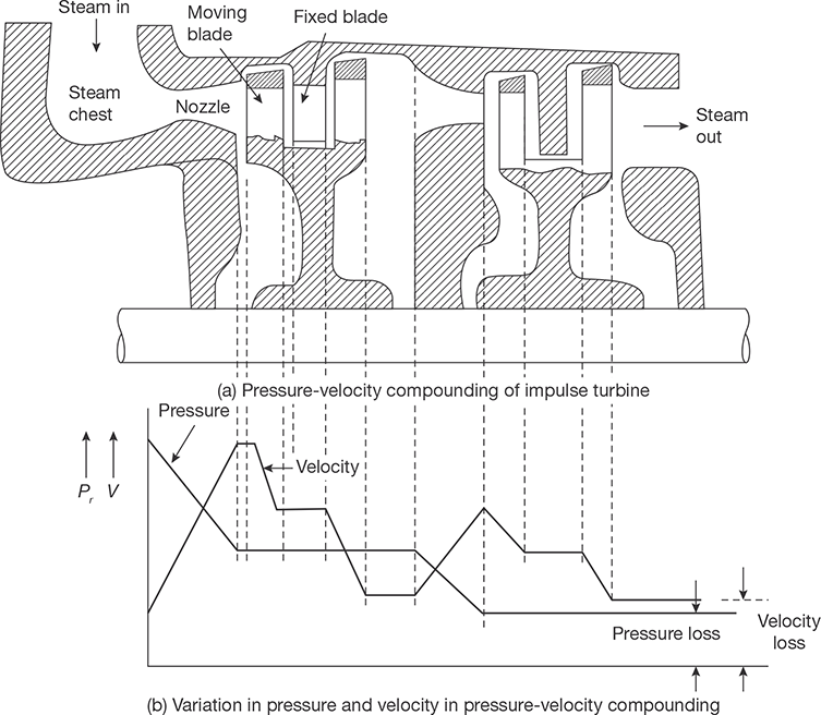
FIGURE 5.13
Pressure-Velocity Compounding of Impulse Turbine
In this case, expansion of steam in nozzle creates impulse on blades and the reaction due to the minor expansion of steam during passing through moving blades. The small drop in pressure of steam in the moving blades gives back pressure to the moving blades in the direction opposite to the velocity. In this turbine there are stages of fixed blades and moving blades; fixed blades act as nozzles that create an impact on the moving blades by reducing the pressure and increasing the velocity.
Since the moving blade channels are also of nozzle shape. Due to the expansion of steam, while flowing through the blades, there is an increase in kinetic energy that produces a reaction in the opposite direction (by Newton’s third law of motion). The blades rotate due to both the impulse effect and the reaction force of steam jets. Such turbines are called impulsereaction turbine or simply a reaction turbine.
The degree of reaction (R) of these turbines is defined as:
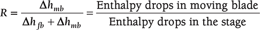
where, mb = moving blades
fb = fixed blades
Note:
- If enthalpy drops in moving blade are zero, the degree of reaction will be zero. This is a case of the pure impulse turbine.
- If enthalpy drops in the fixed blade are zero, the degree of reaction will be one. This is a case of the pure reaction turbine.
- If enthalpy drops in the moving blades are equal to the enthalpy drop in the fixed blades, the degree of reaction will be ½ (half). This is a case of the Parson’s reaction turbine.
Reheat Factor
It is the ratio of cumulative heat drops and isentropic heat drops in multistage turbine.

FIGURE 5.14
Enthalpy Drops in Multistage Turbine

The line which joins the actual points at the end of expansion in each stage is known as condition line (Figure 5.14).

Velocity Diagram for Reaction Turbine
The velocity diagram for 50% reaction turbine is shown in Figure 5.15. Since,
Therefore, Vr1 = V2 and β1 = 180 − δ
Also, β1 ≠ β2, the blades are unsymmetrical and ΔVα = 0. There is no axial thrust in 50% reaction turbine. However, there will be considerable tangential thrust produced due to the pressure difference across the blades in each rotor disc since there is a pressure drop of steam across the moving blades.
The diagram work per kg of steam,
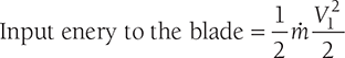
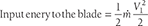
Energy input to blades/kg of steam 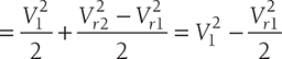
Now, ![]()
Therefore, energy input to the blades 
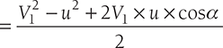
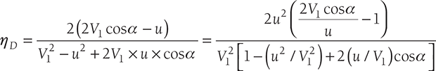
Putting u /V1 = ρ as the velocity ratio
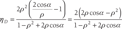
There is an optimum value of ρ at which ηD becomes maximum. Differentiating ηD with respect to ρ and equating to zero. We get,

EXAMPLE 5.2
A reaction turbine has the degree of reaction 50% (i.e., Parson’s reaction turbine) and running at 600 rpm develops 10 MW using 10 kg/kWh of steam flow rate. The exit angle of the blades is 180 and the velocity of steam relative to the blade at the exit is 1.5 times the mean peripheral speed. At a particular stage in the expansion, the pressure is 1.2 bar and the steam quality is 90%. Calculate for the stage:
- Blade height assuming the ratio of Dm/hb as 12
- Diagram power

FIGURE 5.16
Velocity Triangle
SOLUTION
Velocity triangle is shown in Figure 5.16
In a Parson’s reaction turbine,
V1 = Vr2, V2 = Vr1,
B1 = δ and β2 = α = 180
N = 600rpm, P = 10MW, ṁ = 10kg / kWh
Volume of steam at 1.2 bar from steam table
V1 = Vf + xVfg = 0.001046m3 / kg + 0.9 × 1.454m3 / kg = 1.382m3 / kg
Volume flow rate of steam, ṁ × V1 = πDmhbV1 sin α
27.77kg / sec × 1.382m3 / kg = π(12hb )hb (180πhb )sin180
Diagram power, PD = ṁ × ΔVω × u = 236.88kW
EXAMPLE 5.3
In a 4-stage turbine steam is supplied at 240 N/cm2 and 3440C. The exhaust pressure is 0.686 N/cm2 and the overall turbine efficiency is 0.72. Assuming that work is shared equally between stages and the condition line is a straight line. Find:
- stage pressure
- efficiency of each stage
- reheat factor

FIGURE 5.17
h-s Diagram
SOLUTION
h-s diagram for four stage turbine is shown in Figure 5.17
P1 = 240N / cm2 = 24 bar; t1 = 3440 C; ηT = 0.72; P5 = 0.068 bar
From llier Diagram,
h1 = 3135kJ / kg; P6 = 0.068 bar
Since work shared is equally divided between each stage,
P2 = 6.5 bar, P3 = 1.75 bar, P4 = 0.4 bar, P5 = 0.06 bar
h1 − h6 = 3135kJ /kg − 2140 kJ /kg = 995kJ /kg
h1 − h5′ = 0.72 × 995kJ /kg = 716.4 KJ /kg
⇒ h5′ = h1 − 716.4 kJ /kg>= 3135kJ /kg − 716.4 kJ /kg = 2418.6 kJ /kg
h2′ = 2975kJ /kg, h3′ = 2800 kJ /kg, h4′ = 2620 kJ /kg
h2 = 2885kJ /kg, h3 = 2725kJ /kg, h4 = 2540 kJ /kg, h5 = 2340 kJ /kg.
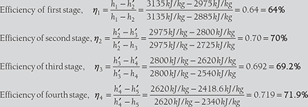
- iii. Reheat factor = Cumulative heat drop/Isentropic heat drop

EXAMPLE 5.4
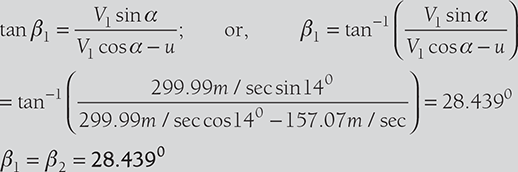
The enthalpy drop in the nozzle of an impulse turbine is 45 kJ/kg. The nozzle is inclined at 14° to the wheel tangent. The average diameter of the wheel is 0.3 m. Wheel runs at 10,000 rpm. Determine the blade inlet angle for sockless entry. If the blade exit angle is equal to the blade inlet angle, determine the work done/kg and also the axial thrust for the flow of 1 kg/s.
Velocity triangle is shown in Figure 5.18
α = 140,D = 0.3m,N = 10000 rpm,ṁ = 1kg/ sec.
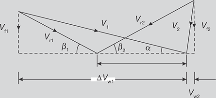
FIGURE 5.18
Velocity Triangle for the Example 5.4
Blade is frictionless, therefore Vr1 = Vr2
Vr1 sin β1 = Vr2 sin β2 = Vf 1 = Vf 2
Axial thrust = ṁ(Vf 1 − Vf 2 ) = 0
Vω1 = V1 cos α = 299.99 m / sec× cos140 = 291.07 m/sec
Vω2 = Vr2 cos β2 − u = 152.39 m / sec× cos 28.439 − 157.07m / sec = −23.051m/sec
(Thus, the direction of Vω2 will be reverse due to −ve sign)
Work done per kg of steam = m· (Vω1 + Vω2 ) × u
= 1kg / sec× (291.07m/ sec− 23.051m / sec) × 157.07 m/sec
= 42.097 kW / kg
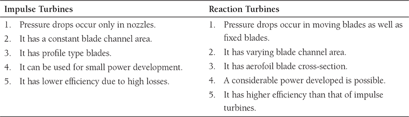
5.3.4 Differences Between Impulse and Reaction Turbines
There are some basic differences between impulse and reaction turbines as mentioned in Table 5.1.
Table 5.1: Differences between Impulse and Reaction Turbines
5.3.5 Losses in Steam Turbines
There may be two types of losses-internal loss and external loss. Internal loss includes all the losses the flow of steam inside the turbine, such as losses in regulating valves, nozzle friction loss, blade friction losses, disc friction losses, partial admission losses, leakage losses, residual velocity losses, and carry over losses, whereas external loss includes pipe loss, pump loss, radiation loss, etc.
5.3.6 Governing of Steam Turbines
Governing of steam turbines is to control the speed of turbines irrespective of load. There are following methods of governing:
- Throttle governing
- Nozzle control governing
- By-pass governing
In throttle governing system, the pressure of steam entering the turbine is reduced at part loads. It is used in only small turbines due to available heat loss in the irreversible throttling process. In nozzle governing system, a number of nozzles (4 to 12) are used with individual propet valve and according to the load requirement steam is supplied to these nozzles through the valves. All nozzles may be in operation at full load and some nozzle may be idle at part load. In the bypass governing system, some part of the steam passes through the first stage and rest of steam passed through the second stage of the turbine. This is used in highpressure turbines where the use of nozzle governing is not possible.
5.4 GAS TURBINES
The gas turbine is a rotating type prime mover which converts the heat energy of gas/air (at high pressure and temperature) into mechanical work. The principle of operation is based on Newton’s Second Law of Motion. The motive power is obtained from the change in momentum of high-velocity jet impinge on curved blades of the turbine.
A simple as turbine consists of: (i) compressor, (ii) combustion chamber, and (iii) turbine. The gas turbine obtains its power by utilization of the energy of burnt gas and air at hightemperature and pressure expanding through the several rings of fixed and moving blades. To get a high pressure in order to 4 to 8 atm of the working fluid (gas) which essential for expansion, a compressor is required. The quantity of working fluid required is very high, therefore, a centrifugal or axial compressor is employed in gas turbines. The compressor is driven by a turbine and coupled with turbine shaft.
If after compression, the working fluid is to be expanded in a turbine and there is no loss in either component, the power developed by the turbine will be equal to the power required by compressor, i.e., work done will be equal to zero. But, the power developed by the turbine can be increased by increasing the volume of the working fluid at constant pressure or increasing the pressure at constant volume. Either of these can be done by heat addition so that the temperature of working fluid can be increased after compression. To get a high-temperature of the working fluid, a combustion chamber is used where combustion of fuel with air takes place.
Since, the compressor is coupled with turbine shaft, the compressor absorbs some part of the power produced by the turbine and the net work done by the turbine will be equal to the difference between work done by Turbine and work absorbed by the compressor. Gas turbines have been constructed to work on the fuels-oil, coal, gas, natural gas, producer gas, blast furnace gas, and pulverized coal.
5.4.1 Classification of Gas Turbine
Gas turbines can be classified on the basis of thermodynamic cycles used and the path of working fluid. On the basis of the thermodynamic cycle, there are two types of gas turbines: (i) Constant pressure cycle, i.e., Joule or Brayton cycle-heat addition and rejection are done at constant pressure, and (ii) Atkinson cycle-heat addition at constant volume and rejection at constant pressure. On the basis of the path of the working fluid, gas turbine can be classified as: (i) Open cycle gas turbine-Working fluid enters from the atmosphere and exhausts to the atmosphere. It works similar to I.C. Engine, and (ii) Closed cycle gas turbineworking fluid is confined within the plant and recirculated. The working is very similar to external combustion engines.
5.4.2 Applications of Gas Turbines
Gas turbines are used for the following purposes:
- Central power stations
- Stand-by power plants
- Locomotive power plants
- Jet engine
- Automotives
- Pumping station
- Main power source for laboratories
- vMarine, etc.
Joule or Brayton Cycle
The air standard Brayton cycle or Joule cycle is a most ideal thermodynamic cycle for a simple gas turbine plant. Its working is shown in Figure 5.19. Atmospheric air is compressed from pressure P1 to a high-pressure P2 in the compressor and delivered to the combustion chamber where fuel is injected and burnt. The combustion process occurs nearly at constant pressure. During the combustion process, heat is added to the working fluid and its temperature rises from T2 to T3. The product of combustion is expanded in the turbine from pressure P3 to atmospheric pressure and discharged into the atmosphere. The turbine and compressor are mechanically coupled to each other; hence the net work is the difference between turbine work and compressor work.

FIGURE 5.19
Flow Diagram of Turbines
The actual gas turbine cycle is an open cycle; therefore fresh air must be continuously introduced into the compressor. In closed cycle gas cycle turbine, heat is added by an indirect method, called heat exchanger so that, there is no mixing of fuel and air. Similarly, the heat is rejected in another heat exchanger called cooler.
In the ideal diagram of Joule cycle, the cycle is assumed to be closed one and heat addition and rejection are only the heat transfer processes at constant pressure. The Joule cycle is shown on P-V and T-S diagram in Figure 5.20.
1-2 Isentropic compression in the compressor thus raising pressure and temperature from P1, T1 to P2, T2.
2-3 Addition of heat at constant pressure raising the temperature from T2 to T3.
3-4 Isentropic expansion of air from high-pressure and high-temperature to low-pressure and low-temperature and thus doing work.
4-1 Rejection of heat at constant pressure to restore the original state of the air.
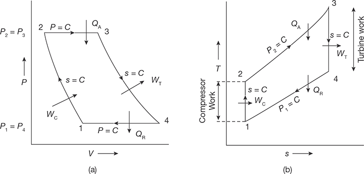
FIGURE 5.20
P-V and T-S Diagrams for Joule Cycle
Heat addition to Combustion Chamber (CC)
Heat rejection from cooler
The net work can also be found as:
Wnet = Work done by turbine − Work doneby compressor
= WT − WC (h3 − h4 ) − (h2 − h1 ) = Cp [(T3 − T4 ) − (T2 − T1 )]
= Cp [(T3 − T2 ) − (T4 − T1 )]

Now, consider the process, 1-2
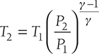
From isentropic expansion process, 3 − 4
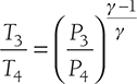
But, P2 = P3 and P1 = P4
Therefore, 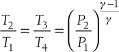
or 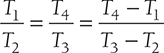
Putting the value of  in Equation (5.5), we get
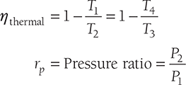
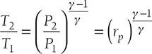
or 
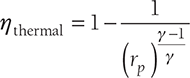
Hence, we can say that the thermal efficiency progressively increases with increasing the value of pressure ratio.
Actual Brayton Cycle
The actual turbine cycle differs from the theoretical cycle in the following manner:
- Due to frictional losses in the compressor and turbine, entropy increases in compression and expansion process. In the ideal case the compressor efficiency (ηc ) and turbine efficiency (ηT ) are 100%, but in practice, they are less than 100% efficient.
- A small pressure loss occurs in the combustion chamber. This loss is so little that it can be neglected for the sake of simplicity.
- The specific heat of combustion gas is slightly higher than that of air. This increase is so little that the specific heat of combustion gas may be taken as that of air for simplicity wherever necessary.

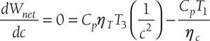
FIGURE 5.21
Actual Brayton Cycle
A T-S diagram for an actual Brayton cycle is shown in Figure 5.21.
1-2 Isentropic compression
1-2′ Actual compression
3-4 Isentropic expansion
3-4′ Actual expansion
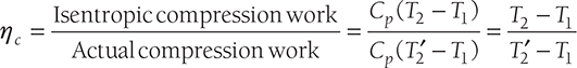
Turbine efficiency, 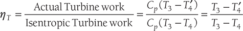
Actual thermal efficency, 

Where WT = Workdone by turbine
WC = Workdone compressor
QA = Actual heat addition
Optimum Pressure Ratio for Maximum Specific Output
In the T-S diagram (Figure 5.22),

Let 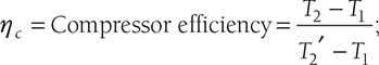
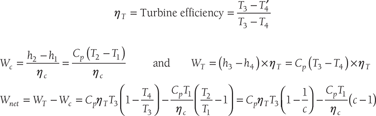
For Maximum work done, Wnet should be differentiated with respect to c and equating to zero.
Therefore,
Since 
If ηT = ηc = 100%;
EXAMPLE 5.5
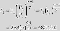
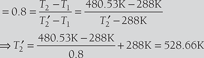
In a gas turbine plant, air is compressed from 1 bar and 150C through a pressure ratio 6:1. It is then heated to 6000C in a combustion chamber and expanded back to atmospheric pressure of 1 bar in a turbine. Calculate the cycle efficiency and the work ratio. The isentropic efficiency of the turbine and compressor are 85% and 80%, respectively.
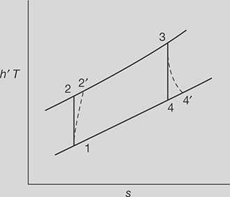
FIGURE 5.23
T-s Diagram
SOLUTION
T-s diagram for the gas turbine is shown in Figure 5.23
P1 = 1bar
T3 = 6000 C + 273 = 873K
P2 = 6 bar, since rp = 6
Efficiency of compressor
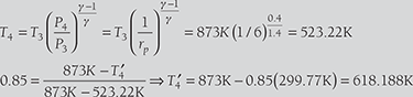
Efficiency of turbine = 0.85 = 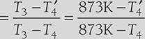

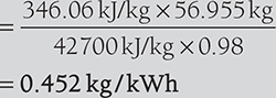
EXAMPLE 5.6
In Example 5.5, if the combustion efficiency is 0.98. Fall in pressure through combustion chamber is 0.1 bar. Determine: (i) the thermal efficiency, (ii) the work ratio, (iii) air rate in kg/kW, and (iv) the specific fuel consumption (v) the air-fuel ratio. For air Cp = 1.005 kJ/kgK; γ = 1.333. Calorific value = 42,700 kJ/kg, Cpg = 1.147 kJ/kg.
SOLUTION
From solution of example 5.5 T1 = 288K, T2 = 480.53, T2′ = 528.6K, T3 = 873K
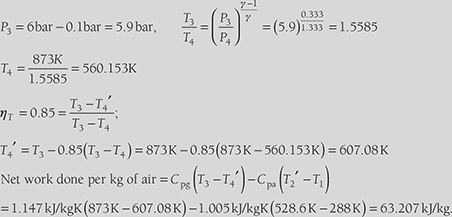
- Thermal efficiency,


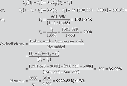
EXAMPLE 5.7
Air enters the compressor of gas turbine plant operating on the Brayton cycle at 1 bar and 27°C. The pressure ratio in the cycle is 6. Calculate the maximum temperature in the cycle and the cycle effi ciency, heat rate. Assume WT = 3 Wc, where WT and Wc are the turbine and compressor work, respectively. Take γ = 1.4.

FIGURE 5.24
T-s Diagram
SOLUTION
T-s diagram for the gas turbine is shown in Figure 5.24.
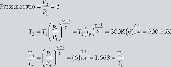
Now, from question, WT = 3Wc
5.4.3 Gas Turbine Cycle with Regenerator
The regenerator is a heat exchanger, which is used to exchange the waste heat of gases exhausted from the turbine to air after compression but before combustion as shown in Figure 5.25. Due to this fuel economy, the efficiency of plant increases.
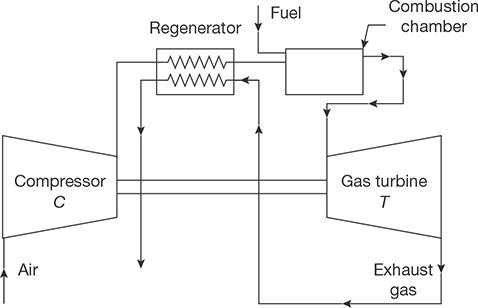
FIGURE 5.25
Gas Turbine with Regenerator
It is theoretically possible to raise the tempera-ture of the compressed air from T2 to T6 = T4 and reduce the temperature of the gas leaving the turbine from T4 to T5 = T2 by arranging a counter flow heat exchanger. The T-S diagram of the Brayton cycle for a gas turbine with regenerator is shown in Figure 5.26.
Addition of heat exchanger in a gas turbine cycle increases the value of both overall efficiency and s specific output for a given pressure ratio, but the increase in output is very nominal because regenerator lowers the pressure ratio at which peak efficiency occurs.
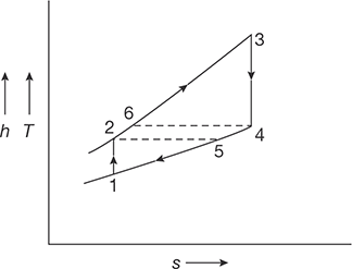
FIGURE 5.26
T-S Diagram of the Brayton Cycle using Regenerator
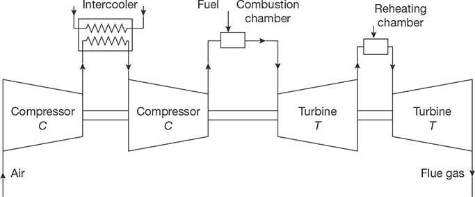
5.4.4 Gas Turbine Cycle with Reheating and Intercooling
Intercooling is added to reduce the compressor work. If the multistage compressor is used, the air is cooled to initial temperature between each stage. The reheater is used to increase the temperature to an initial inlet temperature between each expansion in turbines. Thus, the intercooler and the reheater are used to increase the work output of turbines. The flow diagram using intercooling and reheating is shown in Figure 5.27.
RECAP ZONE
Points to Remember
- The steam power system is a system in which the heat energy of the steam is used to produce mechanical power.
- A steam engine is a reciprocating heat engine that performs mechanical work using steam as its working fluid.
- Steam engines are external combustion engines based on modified Rankine cycle, where the working fluid is separate from the combustion products.
- Steam turbine is a prime mover, which converts the heat energy of steam into mechanical energy by rotating motion of the blade.
- Total energy conversion involves two types of steam expansion: expansion of steam in the nozzle and expansion of steam in turbine blades.
- Pure reaction turbine cannot be used for practical purposes; therefore, the impulse-reaction turbine is referred as reaction turbine.
- If torque produced on the shaft of the turbine is only due to change in momentum of steam and pressure of steam at the inlet and outlet of the turbine being same, it is known as impulse turbine.
- Single row of the nozzle with the single row of the blade is called one stage of the turbine.
- In compounded turbines, the steam is made to expand in a number of stages instead of single stage and turbine speed is reduced which secures the same enthalpy drop of steam.
- Pressure compounding is the splitting of whole pressure drops of steam from steam chest pressure to condenser pressure into a series of small pressure drops across several stages of impulse turbine.
- The whole pressure drops occur in the series of nozzles and there is no pressure drop in fixed blades.
- Pressure-velocity compounding is a combination of pressure compounding and velocity compounding as the steam on passing through each row of moving blades reduces its velocity, but the pressure remains constant during passing through these blades but when steam passes through fixed blades, its pressure reduces and velocity remains constant.
- If steam expands both in the nozzle as well as in blades of the turbine, i.e., pressure at the inlet of the turbine is more than that of the outlet, it is known as an impulse-reaction turbine.
- The degree of reaction (R) of these turbines is defined as the ratio of enthalpy drop in moving blades and enthalpy drop in the stage.
- Reheat factor is the ratio of cumulative heat drops and isentropic heat drops in multistage turbine.
- The gas turbine is a rotating type prime mover which converts the heat energy of gas/air (at high pressure and temperature) into mechanical work.
- A simple as turbine consists of (i) compressor, (ii) combustion chamber, and (iii) turbine.
- Intercooling is added to reduce the compressor work.
- If the multistage compressor is used, the air is cooled to initial temperature between each stage.
- The reheater is used to increase the temperature to an initial inlet temperature between each expansion in turbines.
- The intercooler and the reheater are used to increase the work output of turbines.
Important Formulae
- Tangential thrust Ft =ṁΔVω
- Axial thrust Fα = ṁ ΔVα ; where ΔVα = V1 sinα − v2 sinδ
- Blade work or Diagram work WD = Ft × u = ṁ ΔVω × u
-

-
-

where, mb = moving blades
fb = fixed blades
- Reheat factor = (Cumulative heat drop)/(Isentropic heat drop)
- For Reaction Turbine ρopt = cosα
 WD = (2u − u )u = u 2
 - Efficiency of Gas Turbine

- Optimum Pressure Ration in Gas Turbine

REVIEW ZONE
Objective Questions
Steam Turbine
- In an impulse turbine, steam expands:
- Fully in nozzle
- Fully in blades
- Partly in nozzle and partly in blades
- None of the above
- In impulse turbines, pressure on the two sides of the moving blades:
- Increases
- Decreases
- Remains same
- None of the above
- In impulse turbine, when steam flows over the moving blades:
- Velocity decreases
- Velocity increases
- Pressure decreases
- None of the above
- In a reaction steam turbine, steam expands:
- In nozzle only
- In moving blades only
- Partly in nozzle partly in blades
- None of the above
- De-Lavel Turbine is a:
- Simple impulse turbine
- Simple reaction turbine
- Pressure compounded turbine
- Velocity compounded turbine
- Parson’s Turbine is a:
- Simple impulse turbine
- Simple reaction turbine
- Pressure compounded turbine
- Velocity compounded turbine
- Curtis turbine is:
- Simple impulse turbine
- Simple reaction turbine
- Pressure compounded turbine
- Velocity compounded turbine
- Rateu turbine is:
- Simple impulse turbine
- Simple reaction turbine
- Pressure compounded turbine
- Velocity compounded turbine
- The turbine having identical fixed and moving blades is:
- De-Lavel turbine
- Parson’s reaction turbine
- Rateau turbine
- Zoelly turbine
- In reaction turbine, stage is represented by:
- Each row of blades
- Number of casting
- Number of steam exits
- None of the above
- Blade efficiency is the ratio of:
- Work done of blades and energy supplied to the blades
- Work done on blade and energy supplied to each stage
- Energy supplied per stage and work done on the blades
- Energy supplied to blades and work done on blades.
- Maximum efficiency of Parson’s reaction turbine is equal to:
-
- For maximum efficiency of a Parson’s reaction turbine, the speed ratio is equal to:
-

- cosα
- cos2 α
-

-
- For maximum blade efficiency of a single stage impulse turbine, the blade speed is equal to:
-
- cosα
- cos2 α
-
-
- The compounding of turbine:
- Increases efficiency
- Decreases rotor speed
- Decreases exit loss
- All of the above
Gas Turbine
- 16. A gas turbine works on:
- Rankine cycle
- Carnot cycle
- Joule cycle
- Erriction cycle
- 17. When working fluid in a plant doesn’t come in contact with the atmospheric air, and is used again, turbine is said to work on:
- Open cycle
- Closed cycle
- Semi-closed cycle
- None of these
- 18. When the entire fluid is taken from the atmosphere and is return back to the atmosphere, the gas turbine is said to work on:
- Open cycle
- Closed cycle
- Semi-closed cycle
- None of these
- 19. Efficiency of closed cycle gas turbine as compared to open cycle gas turbine is:
- More
- Less
- Same
- None of the above
- 20. Regenerator in gas turbine:
- Increases thermal efficiency
- Decreases heat loss in exhaust
- Allows use of higher compression ratio
- All of the above
- 21. Compressors used in as turbine are:
- Reciprocating type
- Centrifugal type
- Axial flow type
- None of the above
- 22. Intercooling in gas turbine:
- Increases thermal efficiency
- Decreases compression work
- Increases turbine work
- None of the above
- 23. Reheating in as turbine:
- Increases thermal efficiency
- Decreases compression work
- Increases turbine work
- None of the above
- 24. The air-fuel ratio in gas turbine is:
- 15:1
- 30:1
- 45:1
- 50:1
- 25. The pressure ratio in gas turbine is of the order of:
- 2:1
- 4:1
- 6:1
- 8:1
Fill in the Blanks
- 26. The ratio of useful heat drop to isentropic heat drop is called ____________.
- 27. De-Lavel turbine is normally used for ________ pressure and ____________Speed.
- 28. The pressure-velocity compounded steam turbine allows a _________ pressure drop and hence _________ number of stages are required.
- 29. In impulse-reaction turbine, the pressure drops gradually and continuously over __________ blades.
- 30. The parson’s reaction turbine has __________ and _________ blades.
- 31. In reaction turbine, the degree of reaction is zero. This implies ___________ heat drops in moving blades.
Answers
Theory Questions
- With a neat sketch explain the construction and working of a single stage impulse steam turbine.
- What is compounding of impulse turbine? With a neat sketch explain the working of velocity compounding.
- With a neat sketch explain the working of pressure-velocity compounding of impulse steam turbine.
- Differentiate impulse and reaction type steam turbines.
- Write short notes on: (i) Degree of reaction, (ii) Reheat factor, (iii) Diagram efficiency, and (iv) condition line.
- Explain the methods of governing of the steam turbine.
- Explain the working of closed cycle gas turbine.
- Explain the working principle of the open cycle gas turbine.
- What is a gas turbine? What are the essential components of a gas turbine plant? How it differs from a steam turbine?
- * What are the purposes of regeneration, intercooling and reheating in a gas turbine? Compare Rankine cycle with Carnot cycle.
- * Derive the equation for thermal efficiency of Rankine cycle.
- *Discuss the classification of turbines. Also, discuss compounding of impulse turbine.
- *Explain the working principle of a gas turbine on closed cycle.
- * List any four differences between closed cycle and open cycle gas turbines.
- *What are the advantages of the steam turbine over reciprocating engines?
- * Write the function of the following:
- Nozzle
- Moving blade
- Guide blades in steam turbine
- * Why is gas turbine used in aviation?
- * Derive an expression for the air standard efficiency of a Brayton cycle in terms of pressure ratio.
- *State the working principle of a closed cycle gas turbine. Why is it named as constant pressure turbine?
- *What is compounding of an impulse turbine? State the principle of working of an open-cycle gas turbine. What are the advantages of gas turbines over Steam turbines?
Numerical Problems
- In a single row impulse turbine, the blade speed is 200 m/sec, nozzle angle is 18°. If the steam enters with an absolute velocity of 300 m/sec. Find: (i) inlet and outlet angles of moving blade so that there is no axial thrust, (ii) power developed for a steam flow of 1 kg/sec, and (iii) kinetic energy of steam leaving the stage.
- A reaction turbine has a degree of reaction 50% (i.e., Parson’s reaction turbine) and running at 500 rpm develops 8 MW using 10 kg/kWh of steam flow rate. The exit angle of the blades is 18° and the velocity of steam relative to the blade at exit is 2 times the mean peripheral speed. At a particular stage in the expansion, the pressure is 1.2 bar and the steam quality is 90%.
Calculate for the stage:
- Blade height assuming the ratio of Dm/hb as 12
- Diagram power
- In a 4-stage turbine, steam is supplied at 300 N/cm2 and 3800C. The exhaust pressure is 0.05 N/cm2 and the overall turbine efficiency is 0.7. Assuming that work is shared equally between stages and the condition line is a straight line. Find: (i) stage pressure, (ii) efficiency of each stage, and (iii) reheat factor.
- The enthalpy drop in the nozzle of an impulse turbine is 50 kJ/kg. The nozzle is inclined at 160 to the wheel tangent. The average diameter of the wheel is 0.25 m. Wheel runs at 11,000 rpm. Determine the blade inlet angle for sockless entry. If the blade exit angle is equal to the blade inlet angle, determine the work done/kg and also the axial thrust for the flow of 1 kg/s.
- In a gas turbine plant, air is compressed from 1 bar and 30°C through a pressure ratio 6:1. It is then heated to 600°C in a combustion chamber and expanded back to atmospheric pressure of 1 bar in a turbine. Calculate the cycle efficiency and the work ratio. The isentropic efficiency of the turbine and compressor are 85% and 80%, respectively.
- Air enters the compressor of gas turbine plant operating on Brayton cycle at 1 bar and 20°C. The pressure ratio in the cycle is 4. Calculate the maximum temperature in the cycle and the cycle efficiency, heat rate. Assume WT = 2Wc. Where WT and Wc are the turbine and compressor work, respectively. Take γ=1.4.
- In a gas turbine cycle, the condition of air at the entrance of compressor is 1 bar and 27°C. Pressure ratio is 6. Maximum temperature is 700°C. The exhaust pressure of turbine is 1 bar. Assume 100% efficiency of compressor and 95% efficiency of both turbines and combustion, fall in pressure through combustion chamber is 0.1 bar, calculate: (i) thermal efficiency, (ii) work ratio, (iii) heat rate, (iv) air-rate in kg/kW, (v) specific fuel consumption, and (vi) the air-fuel ratio.
Cp = 1.005 kJ/kg
Cpg = 1.147 kJ/kg
CV = 42,700 kJ/kg
- * 1.5 kg of steam at a pressure of 10 bar and temperature of 250°C is expanded until the pressure becomes 2.8 bar. The dryness fraction of steam is then 0.9. Calculate the change in internal energy. [Hint: Find the value of internal energy of steam (u1) at 10 bar and 250°C, then find the internal energy (u2) at 2.8 bar as u2 = uf + 0.9(ug − uf ) and then find Δu = 1.5kg (u1 − u2 )]