
CHAPTER 10
Air Compressors
Learning Objectives
By the end of this chapter, the student will be able:
- To understand the different types of air compression process
- To demonstrate the single stage and multi-stage reciprocating air compressors
- To calculate the power required to run the compressors
- To describe the working of axial and centrifugal compressors
10.1 INTRODUCTION
The function of the compressor is to compress the gases and vapors from low pressure to high pressure. According to the second law of thermodynamics, this is only possible when work is done on the system, i.e., on the gas or vapor. Compressors have wide industrial and domestic applications such as compression of refrigerants in refrigerators and air conditioning plants, compression of air to fill the air in the wheel of automobiles, use of compressed fluids in nonconventional machining processes, etc.
10.2 CLASSIFICATION OF COMPRESSORS
Compressors can be classified on the basis of a range of pressures, capacity, pressure ratio, and design and principle of operations.
- On the basis of the pressure range, compressors can be classified as:
Low-pressure compressor (below 10 bars)
Medium pressure compressor (10-80 bars)
High-pressure compressor (80-1000 bars)
Hyper compressor (above 1000 bars)
- On the basis of capacity, compressors can be classified as:
Low capacity compressor (below 0.15 m3/sec.)
Medium capacity compressor (0.15 to 5 m3/sec.)
High capacity compressor (above 5 m3/sec.)
- On the basis of pressure ratio, compressors can be classified as:
Fan (Pressure ratio below 1.1)
Blower (Pressure ratio between 1.1 to 2.3)
Compressor (Pressure ratio above 2.3)
- On the basis of design and principle of operations, compressors can be classified as shown in Figure 10.1:

Positive displacement compressor: In this compressor, the pressure is raised by decreasing the volume of gas, i.e., positive displacement of gas.
Dynamic compressor: In this compressor, the kinetic energy imparted to the gas by the rotation of the rotor is converted into pressure energy partly in the rotor and rest in the diffuser.
10.3 RECIPROCATING COMPRESSORS
In these compressors, the gas volume decreases and pressure increases due to the action of one or more reciprocating piston moving axially in one or more cylinders. It may be single acting or double acting, single cylinder or multi-cylinder, and single stage or multi-stage compressors.
Figure 10.2 shows the schematic of a reciprocating compressor. Reciprocating compressors consist of a piston moving back and forth in a cylinder, with suction and discharge valves to achieve suction and compression of the gas. Its construction and working are very similar to a two-stroke engine, as suction and compression of the gas are completed in one revolution of the crank. The suction (inlet) and the discharge (outlet) valves open and close due to pressure differences between the cylinder and inlet or outlet manifolds respectively. The pressure in the inlet manifold is equal to or slightly less than the atmospheric pressure. Similarly, the pressure in the outlet manifold is equal to the pressure of the compressor at the end of compression. The purpose of the manifolds is to provide stable inlet and outlet pressures for the smooth operation of the valves and also provide a space for mounting the valves.
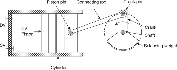
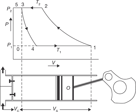
Working principle of ideal reciprocating compressors is diagrammatically shown in Figure 10.3.

FIGURE 10.3
Ideal Reciprocating Compressor
An ideal reciprocating compressor has following assumptions:
- There is no clearance volume in the cylinder.
- Working fluid behaves like a perfect gas.
- There is no friction loss.
- There is no loss during the passing of the fluid through valves.
Process 0-1: This is an isobaric suction process, during which the piston moves from the Top Dead Center (TDC) to the Bottom Dead Center (BDC). The suction valve remains open during this process and gas at a constant pressure P1 flows into the cylinder.
Process 1-2: This is an isentropic compression process. During this process, the piston moves from BDC towards TDC. Both the suction and discharge valves remain closed during the process and the pressure of the gas increases from P1 to P2. Various types of compression process in reciprocating compressors are shown in P-V and T-S diagrams in Figure 10.4.
| Isentropic compression | 1-2' | γ = 1.4 for air |
| Polytropic compression | 1-2 | γ = 1.25 for air |
| Isothermal compression | 1-2" | Temperature remains constant. |
Process 2-3: This is an isobaric discharge process. During this process, the suction valve remains closed and the discharge valve opens. Gas at a constant P2 is expelled from the compressor as the piston moves to TDC.
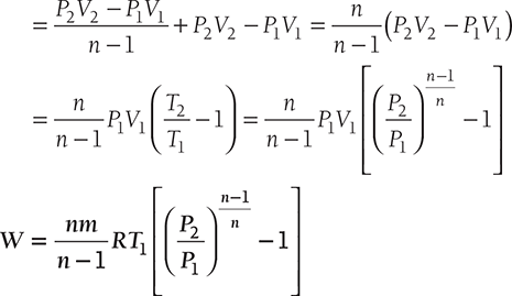
10.3.1 Polytropic Compression
Area 0-1-2-3 represents the net work done when the compression follows the polytropic law.
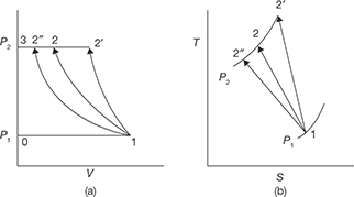
FIGURE 10.4
(a) P-V and T-S Diagrams for Isentropic, Polytropic, and
Isothermal Compression, and (b) Isentropic Compression
Net work on air per cycle = area 0–1–2–3 = Work done during compression (1–2) + work done during air delivery (2–3) – work done during suction (0-1).
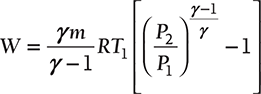
Similarly, for Isentropic compression
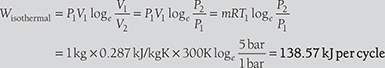
10.3.2 Isothermal Compression
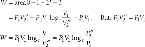
In isothermal compression work done is minimum and is maximum for adiabatic compression.
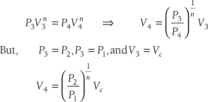
10.3.3 Effect of Clearance on Work Done
10.3.4 Volumetric Efficiency
The volumetric efficiency of a compressor is the ratio of actual free air delivered to the displacement of the compressor.

Substituting the value of in Equation (10.1), we get
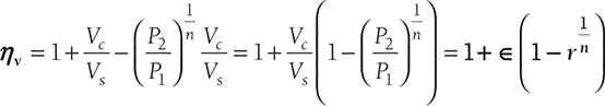
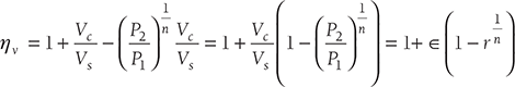
Where ∈ is clearance ratio ![]() and r is pressure ratio
and r is pressure ratio ![]()
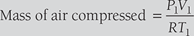
EXAMPLE 10.1
A single cylinder, single acting air compressor has a cylinder diameter of 150 mm and stroke of 300 mm. It draws air into the cylinder at a pressure of 1 bar and temperature 270C. This air is then compressed adiabatically to a pressure of 8 bars if the compressor runs at a speed of 120 rpm, find: (i) mass of air compressed per cycle, (ii) work required per cycle, and (iii) power required to drive the compressor. Neglect the clearance volume and take R = 0.287 kJ/kgK.
SOLUTION
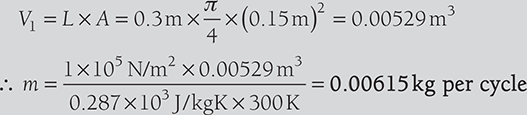
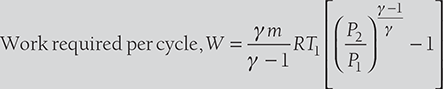
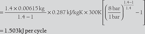
- Power required to run the compressor = Work required per cycle × Cycle per sec

EXAMPLE 10.2

10.3.5 Multistage Compression
A number of stages required depends on the pressure to be developed in the compressor. Normally, following relationships are used with pressure and number of stages.
- Single stage compression is used for delivery pressures up to 5.6 kgf/cm2.
- Two stage compressions are used for delivery pressures up to 5.6 to 35 kgf/cm2.
- Three stage compressions are used for delivery pressures up to 35 to 84 kgf/cm2.
Advantages of multistage compression
- There is little chance of lubrication troubles due to lowering of maximum temperature.
- Leakage loss is minimized.
- There is a gain in volumetric efficiency.
- More uniform torque with the small size of the flywheel can be generated.
Assumption in multistage compression
The following assumptions are usually made in the calculation of work done in multistage compression:
- For each stage, pressures during suction and delivery remain constant.
- The index (n) in polytropic law is same in each stage of compression.
- Intercooling in each stage is done at constant pressure.
- Low pressure and high-pressure cylinders handle the same mass of air.
- There is no interstage pressure drop, i.e., exhaust pressure of one stage equals the suction pressure of the next stage.
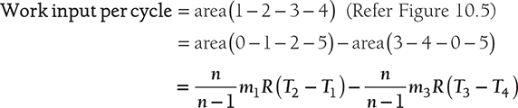
10.3.6 Work Done in Multistage Compression
P-V and T-S diagrams for multistage compression are shown in Figure 10.6.
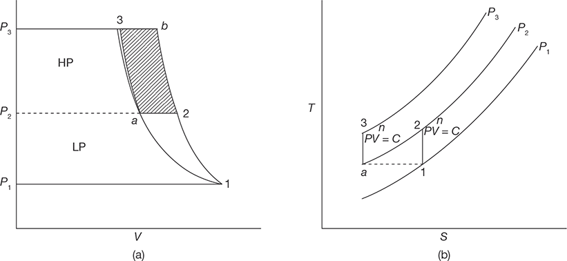
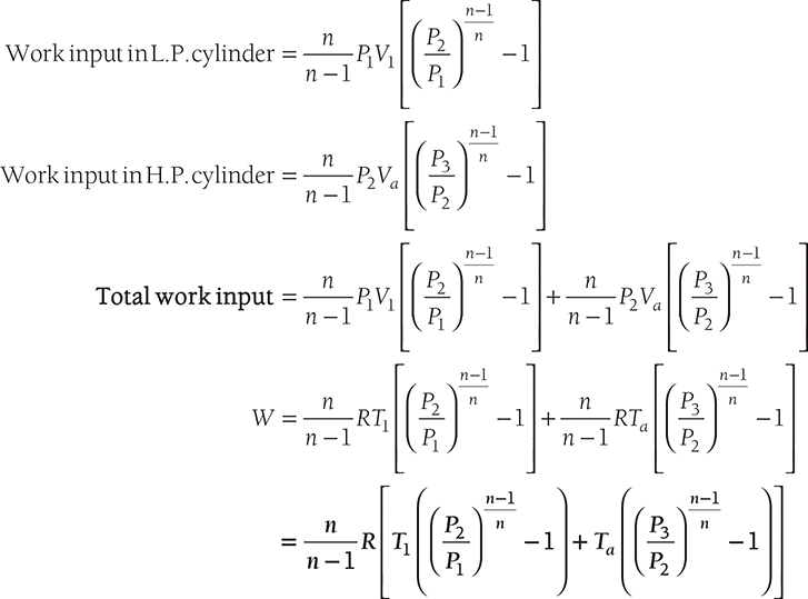
If P1, T1 and delivery pressure P3 are fixed, the optimum value of the intermediate pressure P2 for minimum work can be obtained by setting the derivative dW/dP2 = 0.
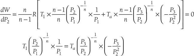
or, 
For perfect cooling, Ta = T1
In general, if there are N stages, the pressure ratio for each stage will be iven by
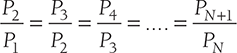
and, 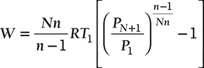
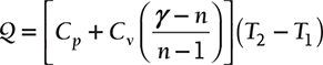
Heat rejected during compression process
Mean Effective Pressure, pm
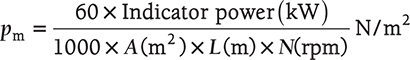 for single acting reciprocating compressor
 for double acting reciprocating compressor
EXAMPLE 10.3
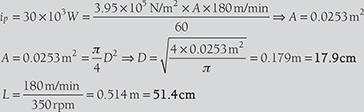
A single stage single acting air compressor has intake pressure 1 bar and delivery pressure 12 bar. The compression and expansion follow the law pV1.3 = constant. The piston speed and rotations of the shaft are 180 m/min and 350 rpm, respectively. Indicated power is 30 kW and volumetric efficiency is 92%. Determine the bore and stroke.
The indicating power of single acting reciprocating compressor is
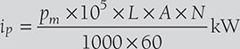
Also, 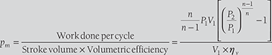

Average piston speed =L×N=180m/min; for single acting reciprocating pump
EXAMPLE 10.4
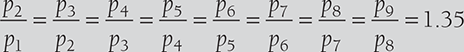
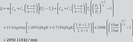
An air compressor has eight stages of an equal pressure ratio of 1.35. The flow rate through the compressor and the overall efficiency are 50 kg/sec and 90%, respectively. If the air enters compressors at a pressure of 1.0 bar and temperature of 313 K. Determine: state of air at the exit of the compressor.
SOLUTION
EXAMPLE 10.5
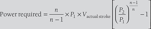
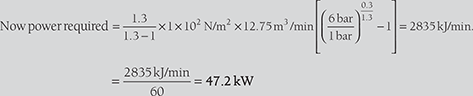
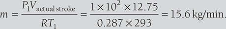
A double acting, single cylinder, reciprocating air compressor has a piston displacement of 0.015 m3 per revolution, operates at 500 rpm and has a 5% clearance. The air is received at 1 bar and delivered at 6 bars. The compression and expansion are polytropic with n = 1.3. Determine: (i) the volumetric efficiency, (ii) the power required, and the heat transferred and its direction during compression if inlet temperature of the air is 293K.
SOLUTION
V = 0.015m3 per revolution;N = 500 rpm;∈= 5%;n = 1.3;P1 = 1bar; and P2 = 6 bar.
10.4 ROTARY COMPRESSORS
10.4.1 Fixed Vane Type Compressors
These compressors belong to the category of positive displacement type as compression is achieved by reducing the volume of the gas. In this type of compressors, the rotating shaft of the roller has its axis of rotation that matches with the centerline of the cylinder; however, it is eccentric with respect to the roller as shown in Figure 10.7. This eccentricity of the shaft with respect to the roller creates suction and compression of the gas. A single vane or blade is positioned in the non-rotating cylindrical block. The rotating motion of the roller causes a reciprocating motion of the single vane. This type of compressor does not require a suction valve but requires a discharge valve. The leakage is controlled through hydrodynamic sealing and matching between the mating components. The effectiveness of the sealing depends on the clearance, compressor speed, surface finish and oil viscosity. Close tolerances and good surface finishing are required to minimize internal leakage.
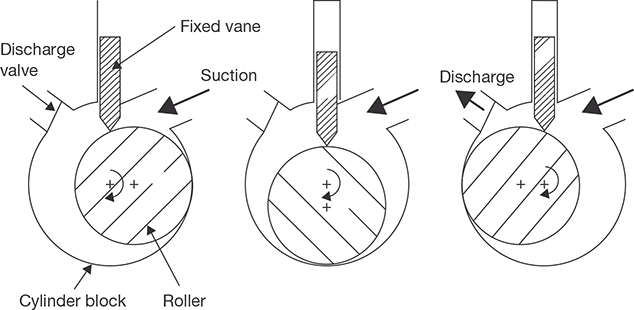
FIGURE 10.7
Fixed Vane Type Rotary Compressor
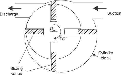
10.4.2 Multiple Vane Type Rotary Compressors
In multiple vane type compressors, the axis of rotation coincides with the center of the roller (O), however, it is eccentric with respect to the center of the cylinder (O’) as shown in Figure 10.8. The rotor consists of a number of slots with sliding vanes. During the running of the compressor, the sliding vanes are held against the cylinder due to centrifugal forces. The number of compression strokes produced in one revolution of the rotor is equal to the number of sliding vanes, thus a 4-vane compressor produces 4 compression strokes in one rotation.
In these compressors, sealing is required between the vanes and cylinder, between the vanes and the slots on the rotor and between the rotor and the end plate. However, since pressure difference across each slot is only a fraction of the total pressure difference, the sealing is not as critical as in fixed vane type compressor. This type of compressor does not require suction or discharge valves, however, check valves are used on discharge side to prevent reverse rotation during off-time due to the pressure difference.
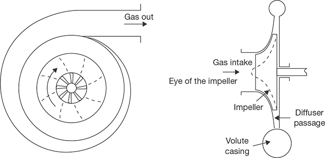
10.5 CENTRIFUGAL COMPRESSORS
In these compressors, the pressure rise takes place due to the continuous conversion of angular momentum imparted to the gas by a high-speed impeller into static pressure. Unlike reciprocating compressors, centrifugal compressors are steady-flow devices hence they are subjected to less vibration and noise. Figure 10.9 shows the working principle of a centrifugal compressor. As shown in the Figure, low-pressure as enters the compressor through the eye of the impeller. The impeller consists of a number of blades, which form flow passages for gas.
From the eye, the gas enters the flow passages formed by the impeller blades, which rotate at very high speed. As the gas flows through the blade passages towards the tip of the impeller, it gains momentum and its static pressure also increases. From the tip of the impeller, the gas flows into a stationary diffuser. In the diffuser, the gas is decelerated and as a result, the dynamic pressure drop is converted into static pressure rise, thus further increase in the static pressure. The gas from the diffuser enters the volute casing where further conversion of velocity into static pressure takes place due to the divergent shape of the volute. Finally, the pressurized gas leaves the compressor from the volute casing. The velocity triangle for the centrifugal compressor is shown in Figure 10.10.
Here,
- V = absolute velocity of gas
- u = blade velocity
- Vr = relative velocity
- V∞ = whirl component of absolute velocity
- Vf = flow or normal component of absolute velocity
Further, suffix 1 and 2 represent the conditions at inlet and outlet of the impeller.
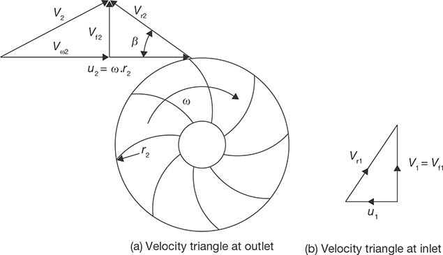
For inlet velocity diagram, it has been assumed that gas enters the impeller eye in an axial direction, i.e., the whirl component of absolute velocity, Vω1is zero. Flow component of absolute velocity, Vf1 = V1 (Figure 10.10 b)
In general, we consider the flow of a gas through a rotor of any shape, the rate of change of angular momentum is given by (Vω2r2 − Vω1r1 )m/sec/kg
It has been observed that for backward curved vanes (β < 900), the tangential compo-nent of absolute velocity is much reduced and consequently for a given impeller speed, the impeller will have a low energy transfer. In the case of forward curved vanes (β > 900), the tangential component of absolute velocity is increased and consequently, the energy transfer for forward curved vane is maximum. However, the absolute velocity at impeller outlet is also increased. The high value of the absolute velocity is not desirable as its conversion into static pressure cannot be carried out efficiently in diffuser section. Normally, backward vanes with β between 20-250 are employed except in the case where the high head is a major consideration.
10.6 AXIAL FLOW COMPRESSORS
In axial flow compressors, the flow proceeds throughout the compressor in a direction essentially parallel to the axis of the machine. The unit consists of an adjacent row of rotor blades and stator blades. One stage of the machine comprises a row of rotor blades followed by a row of stator blades. For efficient operation, the blades are of aerofoil section based on aerodynamic design. The fixed blades serve the following purposes.
- To convert a part of the K.E. of the fluid into pressure energy. The conversion is achieved by diffusion process out in the diverge blade passage.
- To guide and redirect the fluid flow so that entry to the next stage is without shock.
Surging
Surging is caused due to unsteady, periodic, and reversal flow of gas through the compressor when the compressor has to operate at less mass flow rate than a predetermined value. Thus, when flow through the compressor is less than a predetermined value, a surge or pulsation begins and air surges to and fro through the whole compressor instead of giving a stream in one direction.
Choking
Mass flow rate reaches at a maximum value when the pressure ratio becomes unity. This generally occurs when the Mach number (ratio of gas velocity and sound velocity) corresponding to relative velocity at inlet becomes sonic. The maximum mass flow rate possible in a compressor is known as choking flow. Choking means fixed mass flow rate regardless of pressure ratio.
Stalling
The phenomenon of reduction in lift force at higher angles of incidence is known as stalling. It is defined as an aerodynamic stall or the breakaway of the flow from the suction side of the blade aerofoil. The breakaway of flow from the suction side may be due to lesser mass flow rate than designed value or due to non-uniformity in blade profile.
RECAP ZONE
Points to Remember
- The function of the compressor is to compress the gases and vapors from low pressure to high pressure.
- In positive displacement compressor, the pressure is raised by decreasing the volume of gas, i.e., positive displacement of gas.
- In the dynamic compressor, the kinetic energy imparted to the gas by the rotation of the rotor is converted into pressure energy partly in the rotor and rest in the diffuser.
- In reciprocating compressors, the gas volume decreases and pressure increases due to the action of one or more reciprocating piston moving axially in one or more cylinders.
- In isothermal compression work done is minimum and is maximum for adiabatic compression.
- The volumetric efficiency of a compressor is the ratio of actual free air delivered to the displacement of the compressor.
- Fixed van type compressors belong to the category of positive displacement type as compression is achieved by reducing the volume of the gas.
- In these compressors, the pressure rise takes place due to the continuous conversion of angular momentum imparted to the gas by a high-speed impeller into static pressure.
- For backward curved vanes (β < 900), the tangential component of absolute velocity is much reduced and consequently for a given impeller speed, the impeller will have a low energy transfer.
- For forward curved vanes (β > 900), the tangential component of absolute velocity is increased and consequently, the energy transfer for forward curved vane is maximum.
- In axial flow compressors, the flow proceeds throughout the compressor in a direction essentially parallel to the axis of the machine.
- Surging is caused due to unsteady, periodic, and reversal flow of gas through the compressor when the compressor has to operate at less mass flow rate than a predetermined value.
- Choking occurs when mass flow rate reaches at a maximum value when the pressure ratio becomes unity. This generally occurs when the Mach number (ratio of gas velocity and sound velocity) corresponding to relative velocity at inlet becomes sonic.
- The phenomenon of reduction in lift force at higher angles of incidence is known as stalling.
Important Formulae
- Work done in polytropic compression in reciprocating compressor:

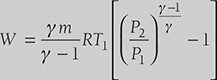
- Work done in isentropic compression in reciprocating compressor:
- Work done in isothermal compression in reciprocating compressor:

- Effect of clearance on work done:

- Volumetric efficiency:
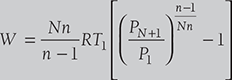
- Work done in multistage compression:
For perfect cooling,Ta= T1
- Heat rejected during compression process:
- Mean Effective Pressure, pm:
 for single acting reciprocating compressor for double acting reciprocating compressor
 - Work done in centrifugal compressor: Work done = (Vω2r2 − Vω1r1 )ω; As Vω1 = 0
= Vω2r2ω = Vω2u2 J/kg
REVIEW ZONE
Multiple-choice Questions
- The most efficient method to compress the air is:
- Isothermal compression
- Adiabatic compression
- Polytropic compression
- None of these
- Maximum work is done in compressing air when the compression is:
- Isothermal compression
- Adiabatic compression
- Polytropic compression
- None of these
- Isothermal compression efficiency can be achieved by running the compressor:
- At a very high speed
- At a very slow speed
- At an average speed
- At zero speed
- Airplane employs the following type of compressor:
- Reciprocating compressor
- Centrifugal compressor
- Axial flow compressor
- None of these
- The ratio of work done per cycle to the swept volume in case of compressor is called:
- Compression ratio
- Compressor efficiency
- Mean effective pressure
- None of these
- Clearance volume in a cylinder should be:
- As large as possible
- As small as possible
- About 50% of swept volume
- None of these
- Clearance volume on a reciprocating compressor is required to:
- Accommodate valves in the cylinder head
- Provide a cushioning effect
- Attain high volumetric efficiency
- Provide a cushioning effect and also to avoid mechanical bang of the piston with the cylinder head
- The net work input required for compressor with increase in clearance volume:
- Increases
- Decreases
- Remain same
- None of these
- Volumetric efficiency is:
- The ratio of stroke volume to clearance volume
- The ratio of air actually delivered to the amount of piston displacement
- Reciprocal of compression ratio
- None of these
- A compressor at high altitude will draw:
- More power
- Less power
- Same power
- None of these
- The machine run by prime mover and used to increase the air pressure is known as:
- Steam turbine
- Gas turbine
- Compressor
- I.C. engines
- A compressor is used:
- In a gas turbine plant
- In supercharging I.C. Engines
- In pneumatic drills
- All of the above
- Ratio of absolute discharge pressure to absolute inlet pressure is known as:
- Compression ratio
- Expansion ratio
- Compression efficiency
- Compressor capacity
- Compressor capacity is:
- The volume of air delivered
- The volume of air sucked
- Both (a) and (b)
- None of these
- As the compression ratio increases, the volumetric efficiency of air compressor:
- Increases
- Decreases
- Remain constant
- None of these
- In reciprocating compressor, clearance volume is provided to:
- Increase volumetric efficiency
- Allow space for valves and to ensure that the piston does not strike the cylinder at the end of the stroke
- Decrease the work done
- All of these
- The clearance volume in the compressor is kept minimum because it affects:
- Volumetric efficiency
- Mechanical efficiency
- Compressor efficiency
- Isothermal efficiency
- Ratio of isothermal horsepower to the shaft horse power to drive a compressor is known as:
- Volumetric efficiency
- Mechanical efficiency
- Overall isothermal efficiency
- Adiabatic efficiency
- If k is the clearance ratio for a reciprocating air compressor, then volumetric efficiency will be:
- 1 + k – K (P2/P1)Vn
- 1 – k + K (P2/P1)Vn
- 1 + k – K (P1/P2)Vn
- 1 – k + K (P1/P2)Vn
- The optimum intermediate pressure P2 in a two stage air compressor having P1 and P3 as suction and delivery pressures respectively is equal to:
- (P1+P2)/2
- P1.P2/2
- (P1+P2)1/2
- (P1.P2)1/2
- In multistage compression with intercooler, the compression obtained is:
- Isothermal
- Adiabatic
- Polytropic
- None of the above
- Compressor in which compression is achieved by a rotating vane or impller to give the air the desired pressure is known as:
- Single stage compressor
- Single acting compressor
- Rotary compressor
- Reciprocating compressor
- In gas turbine, type of compressor used is:
- An axial flow compressor
- A reciprocating compressor
- A centrifugal compressor
- All of the above
- In centrifugal compressor, at a given pressure ratio an increase in speed causes:
- Increase in flow
- Decrease in efficiency
- Decrease in flow
- Both (a) and (b)
- In a centrifugal compressor, the pressure ratio can be increased by:
- Increasing tip speed
- Decreasing inlet temperature
- Both (a) and (b)
- None of the above
- An axial flow compressor gives optimum performance at:
- High speed
- Low speed
- Moderate speed
- None of the above
Fill in the Blanks
- 27. A centrifugal compressor works on principle of conversion of.__________
- 28. A compressor at high altitude will draw__________
- 29. The ratio of outlet whirl velocity to blade velocity in case of centrifugal compressor is called__________.
- 30. For high-pressure compressors, __________ type of valve will be best suited.
- 31. The ratio of isentropic work to Euler work is known as__________.
- 32. Diffuser in compressor is used to__________.
- 33. Phenomenon of choking in compressor means__________.
- 34. Stalling of blades in axial flow compressor means__________.
- 35. Surging is the phenomenon of__________.
- 36. The maximum pressure ratio in single stage single cylinder reciprocating compressor is__________.
Answers
- a
- b
- b
- c
- c
- b
- d
- c
- b
- b
- c
- d
- a
- a
- b
- b
- a
- c
- a
- d
- a
- c
- a
- d
- c
- a
- Kinetic energy into pressure energy
- Less power
- Slip factor
- Propet
- Pressure coefficient
- Convert Kinetic energy into pressure energy
- Fixed mass flow rate regardless of pressure ratio
- Air stream not able to flow the blade contour
- Unsteady, periodic and reverse flow
- 1:5
Theory Questions
- What is a function of the compressor? How do you classify the compressors? Explain the various basis of classification.
- Explain the assumptions of working of the reciprocating compressor. Discuss the working of a reciprocating compressor with a neat sketch.
- Derive the expression of work done by the compressor in isothermal compression, adiabatic compression, and polytropic compression.
- Find the expression for volumetric efficiency of the reciprocating compressor.
- Discuss the assumptions and advantages of multistage compression.
- Explain the working of fixed vane type and multiple vane type compressors.
- Explain the working principle of the centrifugal compressor.
- Write short notes on surging, choking, and stalling.
- *What is compressor?
- *Derive an equation for work done in the case of single stage single acting reciprocating air compressor neglecting clearance.
- *Why is multi-stage compression required? Write advantages of the multi-staging compression.
- *Classify the air compressor. Differentiate between reciprocating compressor and rotary compressor.
- *Discuss about rotary compressors and blower?
Numerical Problems
- A single cylinder, single acting air compressor has a cylinder diameter of 140 mm and stroke of 2800 mm. It draws air into the cylinder at a pressure of 1 bar and temperature 270C. This air is then compressed adiabatically to a pressure of 7 bars if the compressor runs at a speed of 120 rpm, find (i) mass of air compressed per cycle, work required per cycle, and (iii) power required to drive the compressor. Neglect the clearance volume and take R = 0.287 kJ/kgK.
- A single stage reciprocating compressor is required to compress 1 kg of air from 1 bar to 8 bars. The initial temperature of the air is 200C. Calculate work for isothermal, isentropic, and Polytropic compression for n = 1.25.
- A single stage single acting air compressor has intake pressure 1 bar and delivery pressure 10 bar. The compression and expansion follow the law pV1.3 = constant. The piston speed and rotations of the shaft are 200 m/min and 360 rpm, respectively. Indicated power is 40 kW and volumetric efficiency is 90%. Determine the bore and stroke.
- An air compressor has eight stages of an equal pressure ratio of 1.4. The flow rate through the compressor and the overall efficiency are 40 kg/sec and 92%, respectively. If the air enters compressors at a pressure of 1.0 bar and temperature of 300 K. Determine: (i) state of air at the exit of the compressor, (ii) polytropic of small stage efficiency, and (iii) power required to drive the compressor.
- A double acting, single cylinder, reciprocating air compressor has a piston displacement of 0.014 m3 per revolution, operates at 600 rpm and has a 4% clearance. The air is received at 1 bar and delivered at 8 bars. The compression and expansion are polytropic with n = 1.3. Determine: (i) the volumetric efficiency, (ii) the power required, and (iii) the heat transferred and its direction during compression if inlet temperature of the air is 293K.
- *A single stage, the single acting compressor has a bore of 170 mm and stroke of 260 mm. it runs at 130 rpm. The suction pressure is 1 bar and delivery pressure is 9 bar. Find the indicated power if compression (i) follows the law pv1.25 = constant and (ii) is isothermal. Also, find isothermal efficiency. Assume there is no clearance volume.
- *Air enters a compressor at 0.2 Mpa and 30°C having a volume of 2 m3/kg is compressed to 1 Mpa isothermally. Calculate: (i) work down, (ii) change in I.E., and (iii) heat transferred.