
CHAPTER 13
Machine Elements
Learning Objectives
SPRINGS
13.1 INTRODUCTION
Spring is an elastic body whose function is to distort when loaded and to recover its original shape when the load is removed. It works as a flexible joint between two parts or machine elements. It also works as an energy reservoir, it absorbs the energy when loaded and released the same when unloaded.
Applications of Springs
Springs may be used for various purposes. Some of the important applications of the springs are given below as:
- Springs are used for cushioning, absorbing, or controlling of energy due to shock and vibration. For example: Car springs or railway buffers are used for cushioning effect.
- Springs are used to control the motion of machine elements. For example: spring maintains the contact between two machine elements as in the case of cam and follower. In a cam and follower arrangement, a spring maintains contact between the two elements. It mainly controls the motion of follower with respect to the cam.
- Springs are used to create the necessary pressure in a friction device. For example: In the case of a brake, spring is used to create a pressure by the friction disc on the drum; and similarly, in the case of clutch spring is used to create a pressure between two clutch plates. There are a number of similar applications of the springs in the operations of vehicles, such as the application of springs in valve operation in I.C. Engines and in the case of speed control of the governor and hence the fuel and power control, etc.
- Springs are also used to measure the forces. For example: spring is used in the balance and gauges to measure the forces.
- Springs are also used to store the energy. For example: a spiral spring is used in a mechanical clock to store the energy and release slowly; it is also used in many toys to store the energy.
13.2 TYPES OF SPRINGS
Spring classification is not fixed; it depends on its applications. Here some commonly used springs are given as:
- Helical Springs—open coiled and close coiled
- Conical and Volute Springs
- Torsion Springs
- Laminated or Leaf Springs
- Disc Springs
Helical Springs
Helical springs are made of a wire coiled in the form of a helix and are primarily used to bear compressive or tensile loads. The cross-section of wire from which the spring is made may be circular, square or rectangular. The two forms of helical springs are compression helical spring and tension helical spring as shown in Figure 13.1. Open coiled helical springs are used for bearing the compressive load. The helixes angle in the case of open coiled helical spring may be larger, i.e., more than 15°. Close coiled helical spring is used for tensile load and the helix angle, in this case, may vary from 5° to 10°.

FIGURE 13.1
Helical Springs
Conical and Volute Springs
The conical and volute spring, as shown in the Figure 13.2, are used in special applications where the spring rate increases in an increase in load. Another feature of these types of springs is the decreasing number of coils results in an increasing spring rate. This characteristic is sometimes utilized in vibrations problems where springs are used to support the body that have varying mass. The shape of the volute spring is paraboloid with a constant pitch.

FIGURE 13.2
Conical and Volute Springs
Torsion Springs
Torsion springs may be of the helical or spiral type as shown in Figure 13.3 and used to apply torsion. Helical types of springs are used where the load tends to wind up the springs and are used in some electrical mechanisms. Spiral type is used where the loads tend to increase the number of coils and are used in watches and clocks.
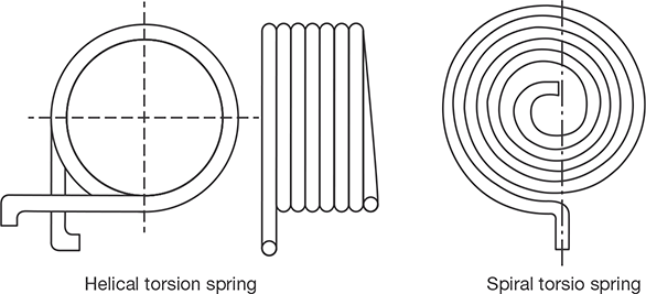
FIGURE 13.3
Torsion Spring
Laminated or Leaf Springs
The laminated or leaf spring is also known as flat spring as shown in the Figure 13.4. It consists of a number of flat plates, known as leaves, of varying lengths held together by means of clamps and bolts. These types of springs are most used in automobiles on the axle to bear the load of the vehicle and minimize the jerk.

Disc Spring
These springs consist of a number of conical discs held together by a central bolt or tube as shown in the Figure 13.5. These springs are used in applications where high spring rates and compact spring units are required.
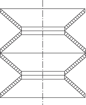
FIGURE 13.5
Disc Spring
13.3 MATERIALS USED FOR SPRINGS
Some of the common materials used for spring manufacturing are given below.
Hard-drawn Wire: This is cold drawn, cheapest spring steel and used for low stress and static load. The material is not suitable at subzero temperatures or at temperatures above 1200°C. Subzero temperature means the temperature below zero degree Fahrenheit.
Oil-tempered Wire: It is a cold drawn, quenched, tempered, and general purpose spring steel, but not suitable for fatigue or sudden loads, at subzero temperatures and at temperatures above 1800°C. Alloy steels are more useful for highly stressed conditions.
Chrome Vanadium: This alloy spring steel is used for high-stress conditions and at hightemperature, up to 2200°C. It is good for fatigue resistance and long endurance for shock and impact loads.
Chrome Silicon: This material can be used for highly stressed springs. It offers good service for long life, shock loading and for temperature up to 2500°C.
Music Wire: This spring material is most widely used for small springs. It is the toughest and has high tensile strength and can withstand repeated loading at high stresses. However, it cannot be used at subzero temperatures or at temperatures above 1200°C. Normally when we talk about springs we will find that the music wire is a common choice for springs.
Stainless Steel: It is generally used as alloy spring materials.
Phosphor Bronze/Spring Brass: It is corrosion resistant and electrical conductor. It is commonly used for contacts in electrical switches. Spring brass can be used at subzero temperatures.
13.4 SHEAR STRESS IN HELICAL SPRINGS
Solid Length: The solid length of a spring is the product of a total number of coils and the diameter of the wire. It is the length when the springs are compressed until the coils come in contact with each other. Mathematically,
Solid length = n × d; where ‘n’ is the number of coils in the spring and ‘d’ is the diameter of the spring wire.
Free Length: Free length of a compression spring is the length of the spring in the free or unloaded condition and is equal to the solid length plus the maximum deflection or compression of the spring and the clearance between the adjacent coils.
Free length, Lf = solid length + max. deflection + clearance between adjacent coils.
Spring Index: It is defined as the ratio of the mean diameter of the coil to the diameter of the wire.
Spring index, C = D/d; where ‘D’ is the mean diameter of the coil and ‘d’ is the diameter of the wire.
Spring Rate: Spring rate (stiffness/spring constant) is the defined as the load required per unit deflection of the spring.
Spring Rate, k = F/ δ; where F is the load applied and δ is the deflection.
Pitch: Pitch of the coils is defined as the axial distance between adjacent coils in the uncompressed state.
Let us consider an open coiled helical spring is subjected an axial compressive load, F as shown in the Figure 13.6. The shear stress will be induced in the wire. The shear stress will be due to axial force, F and also due to the torsion produced in the wire of the spring.
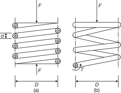
FIGURE 13.6
(a)Open Coiled Spring under Axial Load,
(b) Free Body Diagram of Open Coiled Spring under Axial Load.
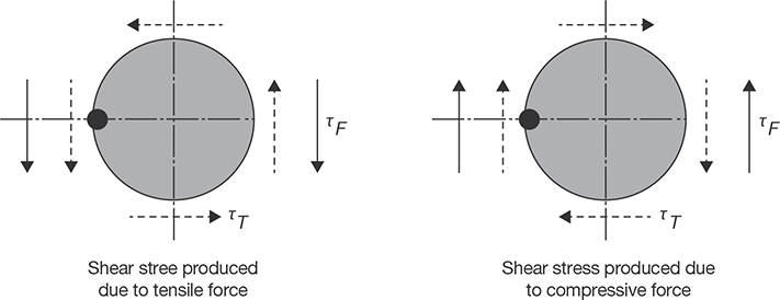
FIGURE 13.7
Shear Stress Produced in the Wire of the Helical Spring
Due to axial loading, the wire will be subjected to shear forces produced due to axial loading and the torque induced as shown the Figure 13.7.
If the diameter of the spring is D, the torque produced in the spring will be ![]()
If the wire diameter is d, the polar moment of inertia will be

Shear stress in the spring wire due to torsion, T will be
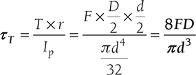
Shear stress in the spring wire due to force F will be

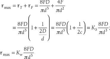
The maximum shear stress in the spring wire will be
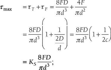
Where ![]()
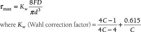
Stresses in Helical Spring with Curvature Effect
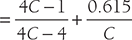
Wahl correction factor is used in the above expression for consideration of curvature factor and shear stress correction factor as:
13.5 DEFLECTION IN HELICAL SPRING
Let l = total active length of wire = πD × n
θ = Angular deflection of the wire due to Torque, T.
Therefore, Axial deflection of the spring δ = θ × D /2
We know that 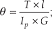 where G is the modulus of rigidity.
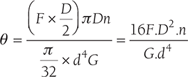
Now, 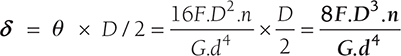
Stiffness of the spring, 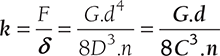
EXAMPLE 13.1
A close coiled helical spring has to absorb 80 Nm of energy when compressed 8 cm. The coil diameter is six times the wire diameter. If there are 10 coils, estimate the diameters of coil and wire and the maximum shear stress. G = 85,000 N/mm2.
SOLUTION
Given U = 80 Nm, x = 8 cm = 80 mm, C = 6, n = 10 and G = 85,000 Nm.
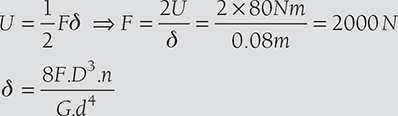
or 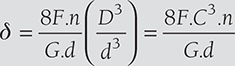

EXAMPLE 13.2
A close-coil helical spring is to have a stiffness of 1,000 N/m in compression, with a maximum load of 50 N and a maximum shearing stress of 125 N/mm2. The solid length of the spring is 50 mm. Find the wire diameter, mean coil radius, and a number of coils. G = 54,000 N/mm2. (Assume shear stress is produced only due to the torque produced in the wire due to axial loading).
SOLUTION


From Equation (13.1) and (13.2)
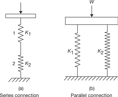
13.6 SERIES AND PARALLEL CONNECTION OF HELICAL SPRINGS
The series connection and parallel connection of the helical springs are shown in the Figure 13.8. For series connection, the equivalent spring stiffness is calculated as:
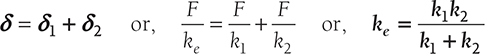
For parallel connection, the equivalent spring stiffness is calculated as:
EXAMPLE 13.3
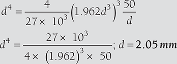
A composite spring has two close coiled helical springs connected in series; each spring has twelve coils at a mean diameter of 20 mm. Find the wire diameter in one if the other is 2 mm and the stiffness of the composite spring is 600 N/m. Estimate the greatest load can be carried out by the composite spring, and the corresponding extension, for a maximum shearing stress of 160 N/mm2. G = 75,000 N/mm2.
SOLUTION
For series connection
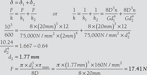
Total extension ![]()
CAM AND FOLLOWER
13.7 INTRODUCTION
The linkages of the cam and follower work are used to transmit the motion from one link to another. A cam is a rotating component in a mechanical linkage that drives the mating component, i.e., follower. The transmitted motion may be reciprocating, linear, simple harmonic motion, etc.
Cam Nomenclature
The different part of the cam and follower are shown in the Figure 13.9.
Cam Profile: Cam profile is the outer surface of the disc cam.
Base Circle: Base circle is the smallest circle, drawn tangential to the cam profile.
Tracepoint: Tracepoint is a point on the follower, trace point motion describes the movement of the follower.
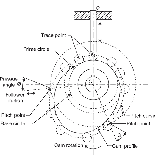
FIGURE 13.9
Cam Nomenclature
Pitch Curve: Pitch curve is the path generated by the tracepoint as the follower is rotated about a stationary cam.
Prime Circle: Prime Circle is the smallest circle that can be drawn so as to be tangential to the pitch curve, with its center at the cam center.
Pressure Angle: The pressure angle is the angle between the direction of the follower movement and the normal to the pitch curve.
Pitch Point: Pitch point corresponds to the point of maximum pressure angle.
Pitch Circle: A circle drawn from the cam center and passes through the pitch point is called Pitch circle.
Stroke: The greatest distance or angle through which the follower moves or rotates.
13.8 TYPES OF CAMS
Cams can be classified into the following three types based on their shapes:
- Plate or Disk Cams: Plate or disk cams are the simplest and most commonly used type of cam. A plate cam is illustrated in Figure 13.10 (a). This type of cam is formed on a disk or plate. The radial distance from the center of the disk is varied throughout the circumference of the cam. Allowing a follower to ride on this outer edge gives the follower a radial motion.
- Cylindrical or Drum Cam: A cylindrical or drum cam is Shown in Figure 13.10 (b). This type of cam is formed on a cylinder. A groove is cut into the cylinder, with a varying location along the axis of rotation. Attaching a follower that rides in the groove gives the follower motion along the axis of rotation.

FIGURE 13.10
Type of Cams - Linear Cam: A linear cam is illustrated in Figure 13.10 (c). This type of cam is formed on a translated block. A groove is cut into the block with a distance that varies from the plane of translation. Attaching a follower that rides in the groove gives the follower motion perpendicular to the plane of translation.
13.9 TYPES OF FOLLOWERS
Followers are classified based on their motion, position, and shape. The details of followers classifications are shown in the Figure 13.11 and discussed below:
- Based on Follower Motion
Based on the follower motion, followers can be classified into the following two categories:
- Translating followers: They are constrained to motion in a straight line and are shown in Figure 13.11 (a) and (c).
- Swinging arm or pivoted followers: They are constrained to rotational motion and are shown in Figure 13.11 (b) and (d).
- Based on Follower Position
Based on the position of the follower relative to the center of rotation of the cam, followers can be classified into the following two categories:
- An in-line follower that exhibits straight-line motion in such a way that the line of translation extends through the center of rotation of the cam and is shown in Figure 13.11 (a).

FIGURE 13.11
Type of Followers - An offset follower that exhibits straight-line motion in such a way that the line of the motion is offset from the center of rotation of the cam and is shown in Figure 13.11 (c).
In the case of pivoted followers, there is no need to distinguish between in-line and offset followers because they exhibit identical kinematics.
- An in-line follower that exhibits straight-line motion in such a way that the line of translation extends through the center of rotation of the cam and is shown in Figure 13.11 (a).
- Based on Follower Shape
Finally, the follower shape can be classified into the following four categories:
- A knife-edge follower that consists of a follower formed into a point shape and drags on the edge of the cam. The knife-edge follower is shown in Figure 13.11 (a). It is the simplest form, but the sharp edge produces high contact stresses and wears rapidly. Consequently, this type of follower is rarely used.
- A roller follower that consists of a follower having roller as a separate part and is pinned to the follower stem. The roller follower is shown in Figure 13.11 (b). As the cam rotates, the roller maintains contact with the cam and rolls on the cam surface. This is the most commonly used follower, as the friction and contact stresses are lower than those for the knife-edge follower. However, a roller follower can possibly jam during steep cam displacements.
- A flat-faced follower that consists of a follower formed with a large flat surface available to contact the cam. The flat-faced follower is shown in Figure 13.11 (c). This type of follower can be used with a steep cam motion and does not jam. Consequently, this type of follower is used when quick motions are required. However, any follower deflection or misalignment causes high surface stresses. In addition, the frictional forces are greater than those of the roller follower because of the intense sliding contact between the cam and follower.
- A spherical-faced follower that consists of a follower formed with a radius face and contacts the cam. The spherical-face follower is shown in Figure 13.11 (d). As with the flat-faced follower, the sphericalface can be used with a steep cam motion without jamming. The radius face compensates for deflection or misalignment. Yet, like the flat-faced follower, the frictional forces are greater than those of the roller follower.
Limits Imposed on the Shape of the Cam Working Surface by the Choice of Follower Type.
- The knife follower does not, theoretically, impose any limit on the shape of the cam.
- The roller follower demands that any concave portion of the working surface must have a radius at least equal to the radius of the roller.
- The flat follower requires that everywhere the surface of the cam is convex.
BUSHING AND ROLLER BEARING
13.10 INTRODUCTION
A bush bearing or bushing is the most common form of a plain bearing. It is inserted into a housing to provide a bearing surface for rotary applications. It’s a common form of the design includes solid (sleeve and flanged), split, and clenched bushings as shown in Figure 13.12. A sleeve, split, or clenched bushing is a sleeve of the length (L), an inner diameter (Di), and outer diameter (Do). The difference between the three types bushing is that a solid sleeved bushing is solid all the way around, a split bushing has a cut along its length, and a clenched bearing is similar to a split bushing but with a clench across the cut. A flanged bushing has a flange at one end extending radially outward. The flange is used to positively locate the bushing when it is installed or to provide a thrust bearing surface.
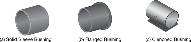
FIGURE 13.12
Sleeve Bushings
A bi-material bearing consists of two materials, a metal shell, and a plastic bearing surface. Common combinations include a steel-backed PTFE-coated bronze and aluminum-backed Frelon. PTFE or polytetrafluoroethylene has unique properties. PTFE coating is also known as Teflon, Xylan, Fluoroplastic, or fluorocarbon coating, and is normally applied to components where a non-stick, dry lubricant or low-friction coating is required. Frelon is a polytetrafluoroethylene based material with other proprietary fillers to increase the bearing characteristics.
13.11 BUSHING MATERIALS
Bronze: A common plain bearing design utilizes a hardened and polished steel shaft and a softer bronze bushing. The bushing is replaced whenever it has worn too much.
Cast iron: A cast iron bearing can be used with a hardened steel shaft because the coefficient of friction is relatively low. The cast iron glazes over therefore wear becomes negligible.
Graphite: A copper and graphite alloy, commonly known as graphalloy, is commonly used in oven and dryers. The graphite is a dry lubricant; therefore it has low friction and requires low maintenance. The copper provides strength, durability, and heat dissipation characteristics.
Application of Lubrication in Bushing
The following types of lubrications are used in bushings:
Class I: The bearings that require the application of a lubricant from an external source (e.g., oil, grease, etc.).
Class II: The bearings that contain a lubricant within the walls of the bearing (e.g., Bronze, Graphite, etc.,). Typically these bearings require an outside lubricant to achieve maximum performance.
Class III: The bearings made of self-lubricating materials. These bearings can run without an external lubricant.
13.12 BEARINGS
Broadly, there are two types of bearings, one is sliding contact or bush bearing and another is rolling contact bearing.
13.12.1 Sliding Contact or Bush Bearings
These bearings are also called as ‘Journal bearings’ or ‘Bush bearings’. A sliding contact bearing is shown in Figure 13.13.
The shaft (called journal) is mounted inside a hollow cylinder (called bearing). When the journal rotates, there is a relative motion between surfaces of journal and bearing. Placing lubricant between the journal and the inner surface of the bearing can reduce the friction resisting the relative motion between journal and bearing. The journal bearings are used to support the load in the radial direction. Generally, the journal rotates while the bearing is stationary. In some cases, the bearing rotates and the journal is stationary. In few cases, both the bearing and journal rotate.

FIGURE 13.13
Bush Bearing
Oil grooves are constructed on journal bearings either by circumferential or cylindrical patterns. A circumferential oil groove bearing is shown in Figure 13.14.
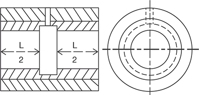
FIGURE 13.14
Circumferential Oil-groove Bearing
The oil groove divides the bearings into two short bearings in the axial direction, each of length (L /2). The presence of groove reduces the pressure developed in the fluid in the plane of groove considerably, as well as the overall pressure. This reduces the load carrying capacity of bearing. Further, the centrifugal force acting on the oil in the circumferential groove may build pressure higher than the supply pressure, restricting the flow of the lubricant into the bearing. These bearings find application in automobiles.
The cylindrical oil-groove bearing is shown in Figure 13.15. The bearing has an axial groove along the full length of bearing. It has higher load carrying capacity compared to the circumferential oil groove bearing. It is more susceptible to vibrations. It is used for gearboxes and highspeed applications. Different patterns of oil grooves are also made by a combination of cylindrical and circumferential grooves.
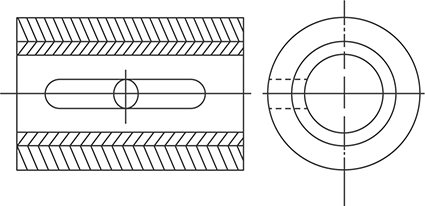
FIGURE 13.15
Cylindrical Groove Bearing
13.12.2 Rolling Contact Bearings
A rolling contact bearing is called as ‘anti-friction bearing. It is an assembly of rolling elements (balls or rollers) placed between the shaft and housing, maintaining radial space between them. The bearing has usually two rings with hardened raceways (outer and inner races), in between hardened steel balls or rollers roll. These balls or rollers are called ‘rolling elements’ and are held in an angularly spaced relationship by a cage or separator. The rolling contact bearing can be classified into ball bearings and roller bearings based on the geometry of the sliding elements. Rolling contact bearings are used to carry radial or thrust loads or the combination of both. Rolling contact bearings are lubricated with grease.
A. Ball Bearing
The nomenclature of the ball bearing is shown in Figure 13.16. The bearing consists of four parts: the outer ring, inner ring, the balls and the separators. The separators prevent the balls from colliding with each other. For the successful design of bearing, the conformity of the ball radius to the raceways radii is very important. Increasing the conformity (i.e., the radius of the ball is increased so that it is closer to the radii of the curvatures of the raceways) increases the area of contact between the balls and raceway. This increases the friction. However, the unit surface stress on the ball is reduced which in turn supports a greater load. Thus, the selection of curvatures for the raceways is a matter of design compromise between friction and load. Most commercial bearings have inner and outer raceways curved to radii between 51.5 and 53% of ball diameter. When the bearing is loaded, elastic and plastic deformations of the balls and raceways increases the conformity; then the balls do not have pure rolling motion. As a result, a small amount of sliding always occurs between the balls and raceways, which affect both the frictional loss and life of bearing.
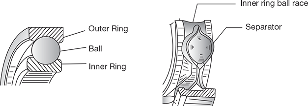
FIGURE 13.16
Nomenclature of Ball Bearing
TYPES OF BALL BEARINGS
Mainly four types of ball bearings are commonly used. These are deep-grove, angular-contact, selfaligning, and thrust ball bearings as shown in Figure 13.17.
Deep-groove Ball Bearing: The widely used ball bearing to support radial load is DeepGroove ball bearing as shown in Figure 13.17 (a). They are mainly designed to support the high radial load and moderate thrust load. They have deep raceways that are continuous (i.e., there are no openings or recesses) over all of the ring circumferences. This type of construction permits the bearings to support relatively high thrust load in either direction. In fact, the thrust load capacity is about 70% of the radial load capacity. It is designed to support radial load can also support high thrust load; because only a few balls carry the radial load, whereas all the balls can withstand the thrust load. In the case of the double-row deep-groove ball bearings, it has two rows of balls rolling in two pairs of races. They have more radial load capacity than that of single row bearings. In other words, they are smaller in diameter compared to single row ball bearings for comparable radial load capacity. However, the proper load sharing between the balls mainly depends on the accuracy of manufacturing.
Angular Contact Bearings: The angular contact bearings as shown in Figure 13.17 (b) are designed in such a way that the centerline of contact between balls and raceways is at an angle to a plane perpendicular to the axis of rotation. This angle is called contact angle. The angular contact ball bearing may be of single or two rows of balls. They are used to carry radial and axial load together or only axial load depending on the magnitude of the angle of contact. The bearings having large contact angle support heavy thrust. The groove curvature radii are generally 52 to 53% of ball diameter. Angular contact single row ball bearings have high radial-load and high unidirectional thrust load capacity than the deep groove ball bearings.
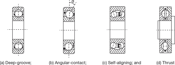
FIGURE 13.17
Types of Ball Bearings
The contact angle is usually less than 40°.In the case of angular contact ball bearings, one side of the outer race is cut to insert balls. This permits the bearing to take the thrust load in only one direction. Therefore, single row angular contact ball bearings are generally used in pairs. In the case of double row angular contact ball bearings (duplex), the balls can be arranged ‘back to back’ and face to face’ or ‘tandem’ configurations (Figure 13.18). The back to back and face to face duplex bearings can accommodate radial load and axial loads in both directions. The tandem bearings can accommodate radial load and heavy axial load in only one direction.
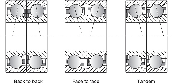
FIGURE 13.18
Duplex Angular Contact Ball Bearing
Self-aligning Ball Bearings: For assembly of shaft and housing which cannot be made perfectly coaxial, the selfaligning ball bearings are the best used. They consist of two rows of balls on a common spherical outer race (Figure 13.17 (c)). In such bearings, the assembly of inner ring and balls can tilt in the outer ring. The loss of load-carrying capacity is inherent in this construction, due to nonconformity of outer raceway with the balls. This is compensated by having a large number of balls in the bearings. Self-aligning ball bearings are used in top drafting rollers and the main shaft of ring spinning machine.
Thrust Ball Bearings: In thrust bearings, the contact angle exceeds 45°. The maximum value this angle can assume is 90°. In such case, races are on the sideways as shown in Figure 13.17 (d). Such a bearing cannot take any radial load and is used only for thrust loads. The shafts carrying bevel or worm or helical gears should be mounted with thrust bearings, except the shafts carrying honeycomb (Herringbone) gears or crossed helical gears of leftand right hands placed alternatively along the shafts.
B. Roller Bearings
Roller bearings have a line contact between the rollers and races against the point contact exhibited by ball bearings. Because of the greater contact area between the rollers and races, the load carrying capacity of straight roller bearings is higher compared with ball bearings of similar size. They are stiffer and have longer fatigue life than comparable ball bearings, and costlier. Roller bearings require almost perfect geometry for the raceways and rollers. A slight misalignment will cause the rollers to skew and get out of line. Straight roller bearings do not take thrust loads. For higher radial load capacity, two or more rows of rollers may be provided. For mounting the ring-spindles (neck bearing), roller bearings are used. The different types of roller bearings are shown in Figure 13.19.

FIGURE 13.19
Roller Bearings: (a) Plain; (b) Tapered; and (c) Spherical
Cylindrical or Plain Roller Bearings: They are the simplest types of roller bearings (Figure 13.19 (a)). The length to diameter ratio of rollers is from 1:1 to 3:1. The outside diameter of the roller is often crowned to increase the load carrying capacity by eliminating any edge loading.
Needle Bearings: For limited radial space, needle bearings are used. In needle bearing, the ratio between the roller length and roller diameter is very large compared with a plain roller bearing. There are two basic forms of needle roller bearings. In one form, the needles are not separated, and in the other form, a roller cage separates the needles. The bearing that does not have the needle separator has a full complement of rollers and therefore, can hold higher load compared with the bearings having roller separators. However, the bearing with needle separator is capable of operating at much higher speeds because the separator keeps the needles from one another, preventing a collision. They are often used to support oscillating shafts.
Tapered Roller Bearings: In tapered roller bearings, the rollers are frustums of a cone shown in Figure 13.19 (b). They are arranged in such a way that tangents of raceways intersect in a common apex point on the axis of the bearing as shown in Figure 13.20.
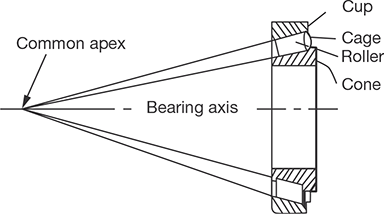
FIGURE 13.20
Tapered Roller Bearing
Tapered roller bearings are capable of carrying both radial and axial loads, but largely used for applications where axial load component predominates. They are often used in pairs to take the thrust load in both directions. Since the inner and outer race contact angles are different, there is a force component, which drives the tapered rollers against the guide flange resulting in heating due to friction. Therefore, these bearings are not suitable for high speeds. Tapered roller bearings are ideally suited to withstand repeated shock loads. Multiple-row tapered roller bearings have high radial-load carrying capacity.
Spherical Roller Bearings: Spherical roller bearings are called as ‘Self-aligning roller bearings’. Spherical roller bearings as shown in Figure 13.19 (c) consists of two rows of spherical rollers, which run on a common spherical outer race. The inner race can freely adjust itself to the angular misalignment of the shaft in the bearings due to mounting errors or shaft deflection under heavy load. They are especially good for heavy loads. Shafts of the cylinder, doffer, stripper roller and calendar roller are mounted in self-aligning roller bearings, which are grease lubricated.
13.13 PROPERTIES OF BEARING MATERIALS
The bearing material should have following characteristics from the service point of view.
- High strength to sustain the bearing load, high compressive, and fatigue strength.
- High thermal conductivity to dissipate the heat quickly.
- Low coefficient of friction. Less wear and tear. Low cost. Bearing materials should not readily weld itself to the shaft material.
- Good corrosion resistance in case the lubricant has the tendency to oxidize the bearing.
- Good conformability. The bearing should adjust to misalignment or geometric errors, materials with a low modulus of elasticity usually have good conformability.
13.14 BEARING MATERIALS
The materials used for sliding contact bearings are Cast iron, brass and alloy materials such as bronzes (copper-tin), Babbitt (alloys of tin-copper-lead-antimony), copper-lead alloys and aluminum-tin alloys. Rubber and synthetic composite materials are also used for certain applications (synthetic bearings). The materials used for rolling contact bearings are alloy steel based on Cr-Ni, Mn-Cr, and Cr-Mo. They should have the capability of being hardened to required level. They require high resistance against wear and fatigue and stability up to 125°C.
RECAP ZONE
Points to Remember
- Spring is an elastic body whose function is to distort when loaded and to recover its original shape when the load is removed.
- Springs are used for cushioning, absorbing, or controlling of energy due to shock and vibration, the motion of machine elements, the necessary pressure in a friction device, measure the forces, and store the energy.
- Helical springs are made of a wire coiled in the form of a helix and are primarily used to bear compressive or tensile loads.
- The conical and volute springs are used in special applications where the spring rate increases in an increase in load.
- Torsion springs may be of the helical or spiral type and used to apply torsion.
- A cam is a rotating component in a mechanical linkage that drives the mating component, i.e., follower. The transmitted motion may be reciprocating, linear, simple harmonic motion, etc.
- A bush bearing or bushing is the most common form of a plain bearing.
- Broadly, there are two types of bearings, one is sliding contact or bush bearing and another is rolling contact bearing.
- The journal bearings are used to support the load in the radial direction.
- A rolling contact bearing is called as ‘anti-friction bearing. It is an assembly of rolling elements (balls or rollers) placed between the shaft and housing, maintaining radial space between them.
Important Formulae
- For Helical Spring: Solid length = n × d; where n is the number of coils in the spring and d is the diameter of the spring wire.
- For Helical Spring: Free length, Lf = solid length + max. deflection + clearance between adjacent coils.
- Spring index, C = D/d; where ‘D’ is the mean diameter of the coil and d is the diameter of the wire.
- Spring Rate, k = F/δ; where F is the load applied and δ is the deflection.
- Shear stress in helical spring:
where Kw (Wahl correction factor) Turbine

- Stiffness of the spring,

- For series connection, the equivalent spring stiffness is calculated as:

- For parallel connection, the equivalent spring stiffness is calculated as:
W = W1 + W2 or, keδ = k1δ + k2δ or, δ = δ1 + δ2
REVIEW ZONE
Multiple-choice Questions
- The load required to produce a unit deflection in the spring is called:
- Modulus of rigidity
- Flexural rigidity
- Spring stiffness
- Torsional rigidity
- The most important properties of the spring material is:
- High elastic limit
- High deflection
- Resistance to fatigue and shock
- All the above
- The purpose of the spring used in brakes and clutch is:
- To measure the forces
- To apply the forces
- To absorb the shocks
- To absorb the strain energy
- A spring used to absorb shocks and vibrations is:
- Open coiled helical spring
- Close coil helical spring
- Leaf spring
- Spiral spring
- The laminated springs are given initial curvature to:
- Have a uniform strength
- Make it more economical
- Make plates flat, when subjected to design load
- None of these
- If a close-coiled helical spring is subjected to load W and the deflection δ, then stiffness of the spring is given by:
- W/δ
- Wδ
- δ/W
- W2δ2
- When a close-coiled helical spring is subjected to an axial load, it is said to be under:
- Shear
- Bending
- Torsion
- Crushing
- When a close-coiled helical spring is cut into two equal parts. The stiffness of the resulting springs will be:
- Same
- Double
- Half
- One-fourth
- Three springs are arranged as shown in Figure 13.21, the spring constant will be:

FIGURE 13.21
- 10 N/mm
- 20 N/mm
- 30 N/mm
- 40 N/mm
- A spring of spring constant K is cut into n equal lengths. The spring constant of each new part will be:
- K/n
- n/K
- n.K
- Kn
- A close-coiled helical spring of stiffness 30 N/mm is arranged with another spring of stiffness 60 N/mm. The stiffness of composite unit is:
- 10 N/mm
- 20 N/mm
- 30 N/mm
- 40 N/mm
- Two close-coiled helical spring of stiffness K1 and K2 are connected in parallel. The combination is equivalent to a single spring of stiffness:


- K1 + K2

- Two close-coiled helical spring of stiffness K1 and K2 are connected in series. The combination is equivalent to a single spring of stiffness:
- K1 + K2
- Which motion of follower is best for high speed cams?
- SHM follower motion
- Uniform acceleration and retardation of follower motion called as.
- Cycloidal motion follower
- All of the above
- Which of the following statements is false for SHM follower motion?
- SHM can be used only for moderate speed purpose
- The acceleration is zero at the beginning and the end of each stroke
- The jerk is maximum at the mid of each stroke
- Velocity of follower is maximum at the mid of each stroke
- Which of the following conditions can be used to minimize undercutting in cam and follower mechanism?
- By using larger roller diameter
- By using internal cams
- By decreasing the size of the cam
- All of the above
- What is meant by jump phenomenon in cam and follower system?
- Follower looses contact with cam surface when cam rotates beyond particular speed due to inertia forces
- Follower looses contact with cam surface when follower rotates beyond particular speed due to gravitational force
- Follower looses contact with cam surface when cam rotates beyond particular speed due to gravitational forces
- None of the above
- Which of the following are functions of bearings?
- Ensure free rotation of shaft with minimum friction
- Holding shaft in a correct position
- Transmit the force of the shaft to the frame
- All of the listed
- A _________ bearing supports the load acting along the axis of the shaft.
- Thrust
- Radial
- Longitudinal
- Transversal
- Load acting on bearing in its plane of rotation is called as________.
- Axial load
- Radial load
- Thrust load
- None of the above
Theory Questions
- What are the applications of springs?
- Explain the classification of springs?
- Discuss the different types of spring materials.
- Derive an expression for shear stress and deflection in a helical spring subjected to an axial force.
- Derive an expression for the equivalent spring constant when two similar springs are connected: (a) in parallel, (b) in series.
- What do you mean by cam and cam followers? Give some example of their industrial applications?
- Discuss the classification of the cam and followers.
- What are the different types of bushes? Discuss its applications in engineering.
- What is the difference between sliding contact bearings and rolling contact bearings?
- Explain the different types of ball bearings used in the industry.
- Discuss the use of roller bearings.
- What are the different types of engineering materials used for manufacturing of bearings?
- What are the properties required for the bearing materials?
- Explain the thrust loading and radial loading in the bearing.
Numerical Problems
- A close coiled helical spring has to absorb 60 Nm of energy when compressed 5 cm. The coil diameter is six times the wire diameter. If there are 18 coils, estimate the diameters of coil and wire and the maximum shear stress. G = 85,000 N/mm2.
- A close-coil helical spring is to have a stiffness of 800 N/m in compression, with a maximum load of 40 N and a maximum shearing stress of 120 N/mm2. The solid length of the spring is 48 mm. Find the wire diameter, mean coil radius, and the number of coils. G = 50,000 N/mm2. (Assume shear stress is produced only due to the torque produced in the wire due to axial loading).
- A composite spring has two close coiled helical springs connected in series; each spring has twelve coils at a mean diameter of 24 mm. Find the wire diameter in one if the other is 3 mm and the stiffness of the composite spring is 640 N/m. Estimate the greatest load can be carried out by the composite spring, and the corresponding extension, for a maximum shearing stress of 160 N/mm2. G = 75,000 N/mm2.