
CHAPTER 16
Couplings, Clutches, and Brakes
Learning Objectives
COUPLINGS
16.1 INTRODUCTION
The term coupling is a device used to connect two shafts together at their ends for transmitting the power. There are a number of coupling devices used to couple two shafts but in this chapter, only a few important couplings have been introduced for an understanding of the students. There are two general types of couplings: (i) rigid, and (ii) flexible.
16.2 RIGID COUPLING
Rigid couplings are designed to draw two shafts together tightly so that no relative motion can occur between them. This design is used for some special kinds of equipment in which precise alignment of two shafts is required. In such cases, the coupling must be capable of transmitting the torque in the shafts. Rigid couplings should be used only when the alignment of the two shafts can be maintained very accurately, not only at the time of installation but also during operation. If significant angular, radial or axial misalignment occurs, stresses that are difficult to predict and that may lead to early failure due to fatigue will be induced in the shafts. The load path is from the driving shaft to its flange, through the bolts, into the mating flange, and out to the driven shaft. The torque places the bolts in shear.
It consists of two cast iron flanges which are keyed to the shafts to be joined as shown in Figure 16.1. The flanges are brought together and are bolted in the annular space between the hub and the projecting flange. The protective flange is provided to guard the projecting bolt heads and nuts. The bolts are placed equispaced on a bolt circle diameter and the number of bolts depends on the shaft diameter d.

FIGURE 16.1
Rigid Flange Coupling
Advantages of Rigid Flange Coupling
- It has high torque transmission capacity.
- It is easy to assemble and disassemble.
- It is a simple design and easy to manufacture.
Disadvantages of Rigid Flange Coupling
- It cannot tolerate misalignment between two shafts.
- It can be used only where the notion is free from shocks and vibrations.
- It requires more space than that of another coupling like muff coupling.
16.3 FLEXIBLE BUSHED COUPLING
In a rigid coupling, the torque is transmitted from one-half of the coupling to the other through the bolts and in this arrangement, shafts need be aligned very well. However, in the bushed coupling, the rubber bushings over the pins (bolts) (as shown in Figure 16.2) provide flexibility and these coupling can accommodate some misalignment. Because of the rubber bushing, the design for pins should be considered carefully.
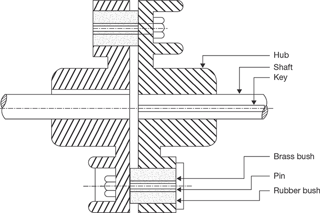
FIGURE 16.2
Flexible Bushed Coupling
Advantages of Flexible Bushed Coupling
- It can bear 0.5 mm of lateral or axial misalignment and 1.5° of angular misalignment.
- It prevents transmission of shock from one shaft to the other and absorbs vibrations.
- It is used for transmission of high torque.
- It is easy to assemble and disassemble due to the simple design.
Disadvantages of Flexible Bushed Coupling
- Its cost is higher than the rigid flange coupling.
- It requires more radial space.
16.4 UNIVERSAL JOINT
To accommodate misalignment between mating shafts for more than the 3°, a universal joint is used. Angular misalignments of up to 45° are possible at low rotational speeds with single universal joints. It consists of two yokes, a center bearing block, and two pins that pass through the block at right angles. Approximately 20 to 30° is more reasonable for speeds about 10 rpm. Since universal joints have the disadvantage that the rotational speed of the output shaft is non-uniform in relation to the input shaft. A double universal joint allows the connected shafts to be parallel and offset by large amounts as shown in Figure 16.3. Furthermore, the second joint cancels the non-uniform oscillation of the first joint so the input and the output rotate at the same speed.

FIGURE 16.3
Universal Joint
CLUTCHES
16.5 INTRODUCTION
Clutch is a device which is used to engage and disengage the driven shaft from driving shaft during the motion to change the gears meshing without stopping the driving shaft. Its operation is based on the friction between two surfaces; friction torque is applied by the driving shaft on the driven shaft.
Clutch may be classified as:
- Single plate clutch or disc clutch.
- Multi-plate disc clutch.
- Conical clutch.
- Centrifugal clutch.
16.6 SINGLE PLATE CLUTCH
In a single plate clutch, a flywheel ‘A’ is bolted to a flange on the driving shaft B. The friction plate C is fixed to a hub which can slide on the spline i.e., driven shaft ‘D’. Two rings of friction material are riveted to flange ‘A’ and the plate ‘C’. The pressure plate ‘E’ is bushed internally, so as to revolve freely on shaft D and is integrated with withdrawal force F. A number of spiral springs are arranged around the clutch at ‘S’ as shown in Figure 16.4 (a), which provides axial thrust between friction surfaces.
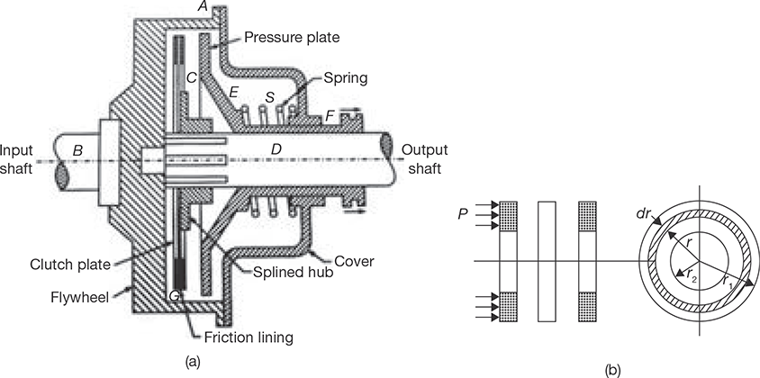
FIGURE 16.4
(a) Single Plate Clutch (b) Friction Plate
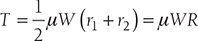
When the withdrawal force is removed, the spring forces the pressure plate ‘E’ against the ring G. The friction between the contact surfaces of rings ‘G’ and plate ‘C’ transmits a torque on ‘D’ and driven shaft starts to rotate.
Let W = axial load on the plate
T = torque transmitted by clutch
P = axial pressure intensity
r1 and r2 = external and internal radii of friction plate
μ = coefficient of friction
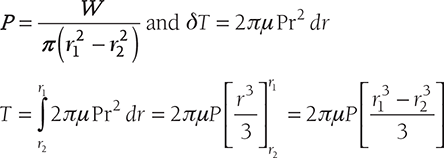
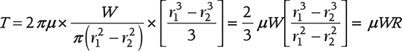
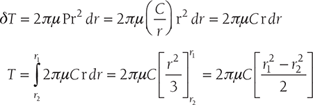
Axial force on a small elemental ring of radius r and width dr, δW = P × 2πrdr
Frictional force, Fr = μδW = μ × P × 2πrdr
Torque, δT = Fr × r = μ × P × 2πrdr × r = μP2πr2dr
Now, there are two conditions: (i) Uniform pressure for new clutch plate, and (ii) uniform wear for old or weared clutch plate.
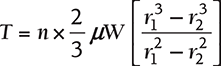
Putting the value of P, we get
where R is mean radius and equals to 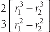
Case II: Uniform Wear
![]() or P × r = constant, C
or P × r = constant, C
Normal force on the ring ![]()
Total force on the friction plate, 
or 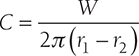
Putting the value of C, we get
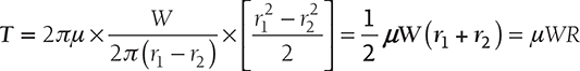
where R is mean radius and equals to ![]()
EXAMPLE 16.1
A single plate disc clutch, both sides effective, has outer and inner radii as 250 mm and 150 mm. The maximum intensity of pressure at any point in the contact surface is not to exceed 0.1 N/mm2. If the coefficient of friction is 0.25, find the power transmitted by the clutch at a speed of 3,000 rpm: (i) assuming uniform wear, and (ii) assuming uniform pressure.
- Considering uniform wear
W = P × 2πr2 (r1 − r2) = 0.1N / mm2 × 2π × 150 mm (250 mm − 150 mm)
= 9424.77 N
Mean radius,

Torque, T = n × µ × W × R = 2 × 0.25 × 9424.77 N × 0.2 m = 942.47 Nm.
Power,

- Considering uniform pressure
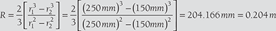
W = P × π (r12 − r22 ) = 0.1N / mm2 × π((250 mm)2 − (150mm)2 ) = 12566.371N
Mean radius,
Torque, T = n × µ × W × R = 2 × 0.25 × 12566.371N × 0.204 m = 1282.871Nm.
Power,

EXAMPLE 16.2
A single plate disc clutch has both of its sides effective, transmits power at 250 rpm. The coefficient of friction is 0.25. The outer and inner radii of the friction plate are 100 mm and 40 mm, respectively. Assuming uniform wear of the clutch, the maximum pressure intensity is 0.1 N/mm2. If the moment of inertia of the rotating part of the clutch is 8 kgm2, calculate the time to attain the full speed by the machine and the energy lost during slipping of the clutch.
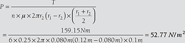
Assuming uniform pressure, find the intensity of pressure and compare the power transmitted with uniform wear to that with uniform pressure.
SOLUTION
- Considering uniform wear
W = P × 2πr2 (r1 − r2 ) = 0.1N / mm2 × 2π × 40 mm (100 mm − 40 mm) = 1507.96 N
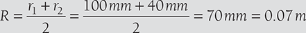
Mean radius,
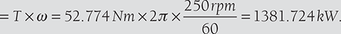
Torque, T = n × µ × W × R = 2 × 0.25 × 1507.96N × 0.07m = 52.774Nm.
Power,
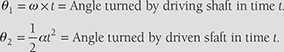
Also,

Energy loss during slipping period

- With uniform pressure
Mean radius,
Torque, T = n × µ × W × R = 2 × 0.25 × 1507.96 N × 0.074 m = 56 Nm.
Power,
16.7 MULTI-PLATE DISC CLUTCH
The function of multi-disc clutch is similar to the single plate clutch but the number of discs in the multi-disc clutch is more than one, i.e., ‘n’ as shown in Figure 16.5.
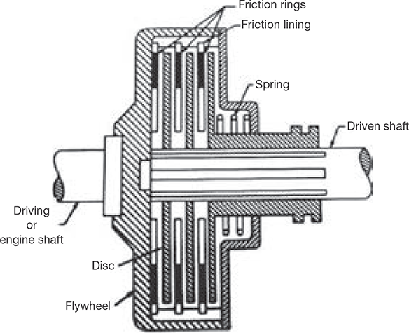
FIGURE 16.5
Multi-disc Clutch
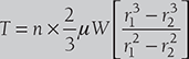
Torque for Uniform Pressure
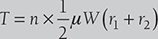
Torque for Uniform Wear
EXAMPLE 16.3
A multi-disc clutch has 4-discs on the driving shaft and 3-discs on the driven shaft. The outside diameter of the contact surface is 240 mm and inside diameter 160 mm. Assuming uniform wear and coefficient of friction as 0.25, find the maximum axial intensity of pressure between the discs for transmission of 20 kW at 1,200 rpm.
Number of pair of contact surfaces = n1 + n2 − 1 = 4 + 3 − 1 = 6
Power 
Considering uniform wear
Mean radius, ![]()
Torque, 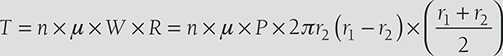
16.8 CONE CLUTCH

FIGURE 16.6
Cone Clutch
In cone clutch, the friction surfaces make a cone of an angle 2β (Figure 16.6). The normal force on the cone is ![]() where β is the semi-cone angle. The main advantage of cone clutch is that the normal force is increased, since sin β ≤ 1.
where β is the semi-cone angle. The main advantage of cone clutch is that the normal force is increased, since sin β ≤ 1.
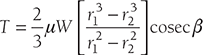
Torque for Uniform Pressure
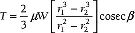
Torque for Uniform Wear
EXAMPLE 16.4
A cone clutch having a mean diameter of 200 mm and semi-cone angle of 12.5° transmits a torque of 200 Nm. The maximum normal pressure at the mean radius is 0.1 N/mm2. The coefficient of friction is 0.25. Calculate the width of the contact surface. Also, find the axial force to engage the clutch.
SOLUTION
T = µ × Fa × Rm × cosecβ

Also, ![]()
or, ![]()
EXAMPLE 16.5
A cone clutch has a cone angle of 30°. The maximum pressure between contact surfaces is limited to 0.25 N/mm2 and width of the contact surface is half of the mean radius. Find the radii of the conical surface to transmit 20 kW at 1500 rpm assuming uniform wear condition. Coefficient of friction is 0.25.
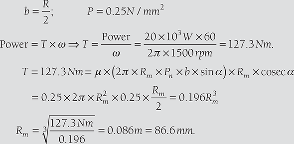
Solving Equations (16.1) and (16.2), we get
r2 = 81.92 mm
16.9 CENTRIFUGAL CLUTCH
Centrifugal clutch works on the principle of centrifugal force. When the driving shaft rotates at high speed, the shoes move radially outward. The outer surfaces of the shoes are covered with friction material which engages the pulley. Thus, pulley rotates with the driving shaft. The engagement of shoes with the pulley is shown in Figure 16.7. This type of clutch is generally used in motor pulley. The spring force resists the centrifugal force, thus prevents the engagement at a lower speed.
Fs = Spring force = mω12r
where ω is the angular speed of the shaft.
Torque, T = F × R = μ.n.( Fc − Fs ).R
where n is a number of shoes.
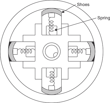
FIGURE 16.7
Centrifugal Clutch
EXAMPLE 16.6
There are four shoes in a centrifugal clutch. The mass of each shoe is 10 kg and when the clutch is at rest, the force exerted by spring on the shoe is 400 N. The clearance between shoe and drum surface is 4 mm. Spring constant is 40 N/mm. The distance of the center of mass of shoe from the axis is 150 mm. The internal diameter of the drum is 320 mm. The coefficient of friction is 0.025; find the power transmitted by the clutch at 400 rpm.
SOLUTION
Operating radius, r1 = 150 + 4 = 154 mm.
Centrifugal force, 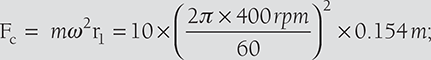
Spring force, Fs = 400 N + Kx = 400 N + 40N / mm × 4mm = 560 N
Tangential frictional force, Ft = µ(Fc − Fs ) = 0.25 × (2702.07 N − 560 N) = 535.51N
Power transmission ![]()
BRAKES
16.10 INTRODUCTION
Brake is a device which is used to bring the body into rest while it is in motion or to hold a body in a state of rest by applying resisting force. There are four types of brakes as given below:
- Block or shoe brake.
- Band brake.
- Band and block brake.
- Internal expanding shoe brake.
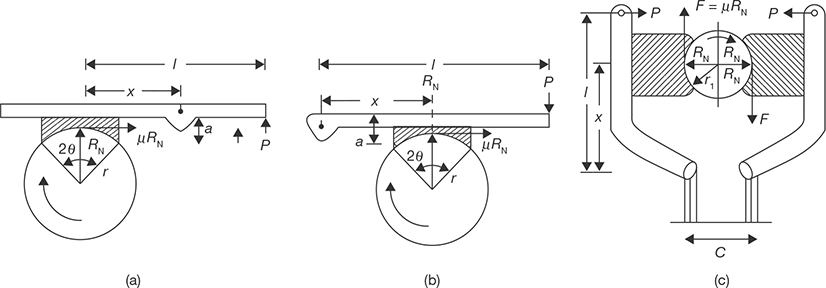
16.10.1 Block or Shoe Brake
In this brake, a shoe or block is pressed against the drum. The force can be increased by using a lever as shown in Figure 16.8. The brake lining for friction is made of softer materials so that it can be replaced easily after wearing.
Let r = radius of drum
µ = Coefficient of friction
RN = Normal reaction on the shoes
P = Force applied on lever
F = Frictional force
In Figure 16.8 (a), taking moment about the pivot for clockwise rotation of drum
or 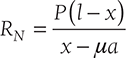
or 
or 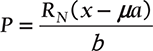
For anticlockwise rotation of drum, 
In Figure16.8 (b), taking moment about pivot for clockwise rotation of drum
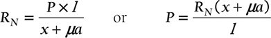
For anticlockwise rotation,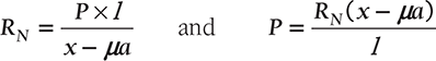
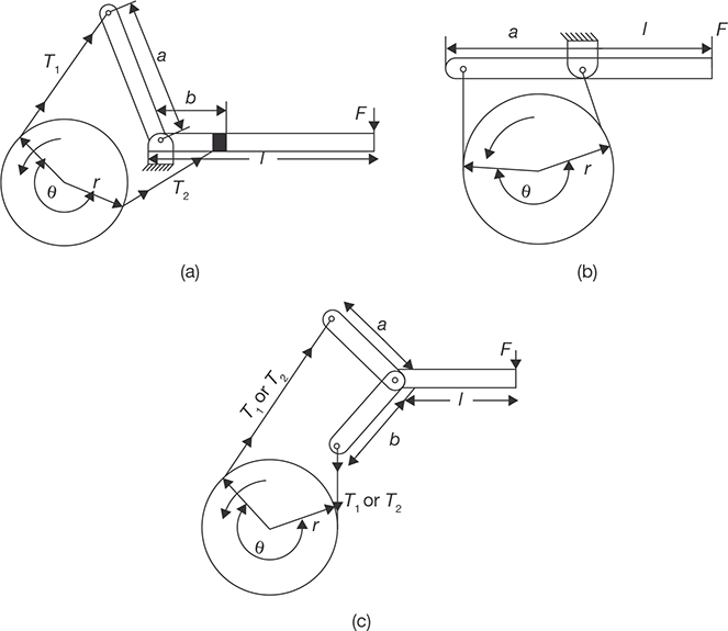
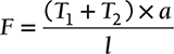
Due to pressure applied by single shoe, there is a side thrust on the shaft of the drum. To counter balance the side thrust, two shoes may be used opposite to each other. In this case, braking torque becomes double which is shown in Figure 16.8 (c).
EXAMPLE 16.7
A single block brake as shown in Figure 16.8 (b) has a diameter of brake drum 1.2 m. It can withstand 250 Nm torque at 500 rpm and coefficient of friction between block and drum is 0.3. Determine the force required to apply when the drum rotates in (a) clockwise direction and (b) anticlockwise direction. The angle of contact is 2θ = 30° and x = 140 mm, a = 30 mm, l = 1000 mm.
SOLUTION
For clockwise rotation

For anticlockwise rotation
= 182 N
EXAMPLE 16.8
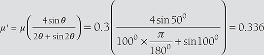
In a double block spring loaded brake as shown in Figure 16.8 (c) following dimensions have been given: drum diameter = 600 mm, angle of contact (2θ) = 100°, coefficient of friction (μ) = 0.3, force applied on the spring = 6 kN, x = 0.5 m, l = 1m, c = 0.1 m. Find the braking torque applied.
For left side block
Taking moment about o.
or, 6000 N × 1m + 0.336 × RN1 (0.3m − 0.05m) − RN1 × 0.5m = 0
or, ![]()
For right side block
or, 6000 N × 1m − 0.336 × RN1 (0.3m − 0.05m) + RN1 × 0.5m = 0
or, RN2 = 10273.973N
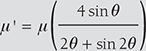
Maximum braking torque, TB = µ'(RN1 + RN2 ) × r
= 0.336 × (14423.07 N + 10273.973 N ) × 0.3m = 2489.461 Nm
16.10.2 Band Brake
Band brake consists of a band in the form of belt, rope or steel band (Figure 16.9). When force is applied at the free end of the lever, the brand is pressed against the external surface of the drum.
Braking torque, T = (T1 – T2) × r
But ![]() where T1 is tension on tight side and T2 is tension in the slack side.
where T1 is tension on tight side and T2 is tension in the slack side.
The effectiveness of braking force varies according to the direction of rotation of the drum, the ratio of length a and b, and the direction of force applied at the end of the lever.
Case I: when a > b and F acts in downward direction and drum rotates in counter clockwise direction.
Case II: when a < b and F acts in downward direction and drum rotates in clockwise direction. In this case, the tensions on the tight side and slack side are reversed, i.e., T2 > T1 and a > b. Brake will be effective only when T1a > T2b.

When  becomes zero or negative, i.e., the brake becomes self-locking.
Case III: When a < b and F acts in upward direction and drum rotates in counter clockwise direction.
or ![]()
As T2 < T1 and b > a, brake will be effective only when T2 × b > T1 × a or 
If  brake becomes self-locking since force required is zero or negative.
Case IV: When a < b and F acts in upward direction and drum rotates in clockwise direction. T2 > T1 and b > a. when a = b, the band cannot be tightened and thus, the brake cannot be applied.
EXAMPLE 16.9
In a differential band brake as shown in Figure 16.9 (a), following data are given:
Drum diameter = 1000 mm, a = 50 mm, b = 250 mm, θ = 270°, μ = 0.3, r = d/2 = 5000 mm, F = 500 N, l = 1200 mm. Calculate braking torque.
SOLUTION
- Since a < b and F acts in downward direction and drum rotates in clockwise direction.
F × l − T1 × a − T2 × b = 0

T1 = 4.111T2
Now, F × l + 4.111T2 × a − T2 × b = 0 or 500 × 1200 + 4.111T2 × 5 − T2 × 250 = 0
⇒ T2 = 13498.313N
T1 = 55491.564N
Braking torque, TB = (T1 − T2) × r = (55491.564 − 13498.313) × 500 = 20.99 kNm
- When drum rotates in counter clockwise direction.
F × l − T1 × a − T2 × b = 0 and

or 500 × 1200 + T1 × 50 − 4.111 T1 × 250 = 0
60,000 + T1 (50 − 1027.75) = 0
T1 = 613.65N; T2 = 2522.73N
Braking torque, TB = (T2 − T1 ) × 500 = (2522.73 − 613.65) × 500
= 954.54 Nm
16.10.3 Band and Block Brake
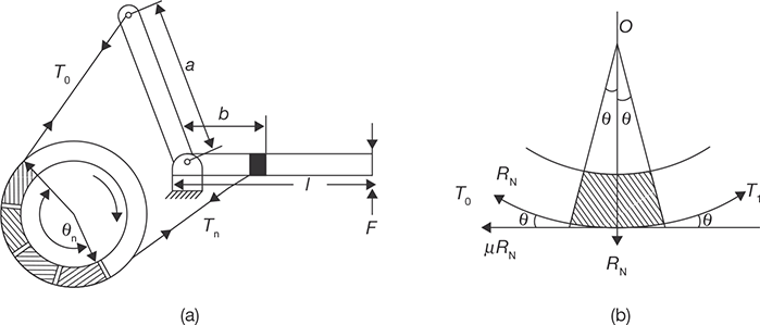
This is a combination of band and block brake. A number of blocks are mounted on the drum and inside the band and brake is applied by pressing the blocks against the drum with the help of the band. To increase the effectiveness of brake blocks are used under the band since blocks have a higher coefficient of friction.
Let T0 = Tension in band on slack side
T1 = Tension in band after one block
-----------------------------------------------
-----------------------------------------------
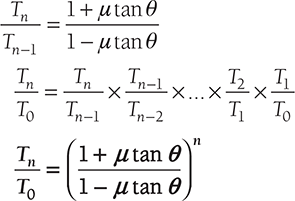
T = Tension in band after nth block
μ = coefficient of friction
Forces on the block are shown in Figure 16.10 (b).
(T1 − T0 )cosθ = µRN and (T1 + T0 )sinθ = RN
or 
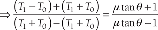
or 
Similarly, 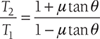
EXAMPLE 16.10
There are 15 blocks in a band and block brake. Each block subtends 30° angle at center. The data given for the brake are: radius of drum = 250 mm, block thickness = 50 mm, coefficient of friction = 0.3, a = 500 mm, b = 40 mm, F = 300 N, l = 1000 mm. Calculate the braking torque.
SOLUTION
Here, a > b, therefore, F should be downward and drum rotates in clockwise direction.
Taking moment about fulcrum, we get
Braking torque, TB = (Tn − T0 ) × (r + t) = (64615.3 N − 5769.2 N)(0.125m + 0.025m)
16.10.4 Internal Expanding Shoe Brake
Internal expanding shoe brake has two semicircular shoes which are lined with friction materials. The outer diameter of the shoe is less than the inner diameter of the drum so that the drum can rotate freely. When the brake is applied, the shoes expand and press the inner surface of the drum and resist the motion. Working of internal expanding shoe brake is shown in Figure 16.11.

It is used in an automobile. It is self-energizing and good heat dissipative. A hydraulic pressure is generated in piston-cylinder arrangement. This hydraulic force is applied equally to both the shoes in the direction shown in Figure 16.11 (a). For counterclockwise rotation of the drum, the left shoe is primary leading shoe while the right shoe is secondary or trailing shoe. The pressure at any point A on the surface will be proportional to its distance l from the pivots.
Normal pressure, PN = K1 × l × cos(90°− β ) = K1 × l × sin β
The normal pressure will be maximum when θ is equal to 90°. Thus PNmax = K2 = PlN
PlN = Maximum pressure interfaced by leading shoe.
PN = K2 sinθ = PlN sinθ
Let b = width of brake lining
µ = coefficient of friction
consider a small element of brake lininon the leading shoe that makes an angle δθ at the center.
Taking moment about fulcrum O1, we get

or 

Similarly, taking moment about fulcrum O2, we get
Here, t superscript is used for trailing shoe.
Thus, the maximum pressure intensities on leading and trailing shoes can be determined.
RECAP ZONE
Points to Remember
- Coupling is a device used to connect two shafts together at their ends for transmitting the power.
- Rigid couplings are designed to draw two shafts together tightly so that no relative motion can occur between them.
- In a flexible coupling, the bushed coupling the rubber bushings over the pins (bolts) provide flexibility and these coupling can accommodate some misalignment.
- To accommodate misalignment between mating shafts for more than the 3°, a universal joint is used.
- Angular misalignments of up to 45° are possible at low rotational speeds with single universal joints.
- Clutch is a device which is used to engage and disengage the driven shaft from driving shaft during the motion to change the gears meshing without stopping the driving shaft.
- The function of multi-disc clutch is similar to the single plate clutch but the number of discs in the multidisc clutch is more than one.
- In a cone clutch, the friction surfaces make a cone of an angle (2β).
- Centrifugal clutch works on the principle of centrifugal force. When the driving shaft rotates at high speed, the shoes move radially outward.
- The outer surfaces of the shoes are covered with friction material which engages the pulley. Thus, pulley rotates with the driving shaft. The engagement of shoes with the pulley.
- The brake is a device which is used to bring the body into rest while it is in motion or to hold a body in a state of rest by applying resisting force.
- Band brake consists of a band in the form of belt, rope or steel band. When force is applied at the free end of the lever, the brand is pressed against the external surface of the drum.
- Band and Block brake is a combination of band and blocks. A number of blocks are mounted on the drum and inside the band and brake is applied by pressing the blocks against the drum with the help of the band.
- Internal expanding shoe brake has two semicircular shoes which are lined with friction materials.
Important Formulae
- Torque on single plate disc clutch
- Uniform pressure

where R is mean radius and equals to

- Uniform wear
where R is mean radius and equals to

- Uniform pressure
- Multi-plate disc clutch
- Torque for uniform pressure
- Torque for uniform wear
- Torque for uniform pressure
- Cone clutch
- Torque for uniform pressure
- Torque for uniform wear

- Torque for uniform pressure
- Centrifugal clutch
Torque, T = F × R = μ.n.(Fc – Fs).R where n is a number of shoes.
- Band and block brake:

- Internal expanding shoe brake
Braking torque;

REVIEW ZONE
Multiple-choice Questions
- The friction moment in clutches with assumption of uniform wear as compared to uniform pressure is:
- More
- Less
- Same
- None of these
- If ϕ be the angle of friction, then radius of friction circle is given by:
- r
- r sinϕ
- r cosϕ
- None of these
- Friction radius in comparison to worn-out will be:
- Same
- More
- Less
- None of these
- For new clutches and brakes, friction radius is equal to:
- For uniform wear condition of brakes and clutches, friction radius is equal to:
- The commonly used angle between the cone surface and horizontal axis for a cone clutch utilizing leather to asbestos lining is about:
- 8°
- 12.5°
- 20°
- 30°
- In a cone clutch, a given torque can be transmitted by a relatively small axial force if the cone face angle is:
- More
- Less
- Same
- Any angle
- For a block brake, the equivalent coefficient of friction is equal to:
- The percentage of total brake effort that results from self-energizing action depends on:
- The location of brake arm pivot point
- The coefficient of friction
- The direction of rotation of the brake drum
- All of the above
- In order to prevent the brake arm from grabbing, the moment of friction force about the brake arm pivot point should be:
- Less than the total required braking effort
- Greater than the total required braking effort
- Equal to the total required braking effort
- None of these
- Coupling, which prevents transmission of shock from one shaft to another, is known as:
- Oldham coupling
- Universal coupling
- Flexible coupling
- Jaw coupling
- In flange coupling, the weakest element is:
- Flange
- Bolt
- Key
- Shaft
- A flange coupling is a:
- Rigid coupling
- Flexible coupling
- Both (a) and (b)
- None of these
- In flange coupling, the flanges are joined together by:
- Head less taper bolts
- Rivets
- Nuts and bolts
- Studs
- Number of bolts in flange coupling should not be less than:
- 2
- 3
- 4
- 8
- A universal coupling is:
- Rigid coupling
- Flexible coupling
- Both (a) and (b)
- None of these
- A universal coupling is used to
connect:
- Whose axes intersect at a small angle
- Which are perfectly aligned
- Which are not aligned
- Have lateral misalignment
Answers
- b
- b
- b
- b
- a
- b
- b
- a
- d
- a
- c
- c
- a
- c
- b
- b
- a
Theory Questions
- Explain the advantages and disadvantages of flexible and rigid couplings.
- Explain the role of clutch in power transmission.
- Derive the formula for torque transmitted by a single plate disc clutch assuming uniform pressure.
- Derive the formula for torque transmitted by a cone clutch assuming uniform wear.
- Which of the two assumptions: uniform pressure and uniform wear would you like to use in designing friction clutch? Explain the reasons.
- Describe the working of centrifugal clutch and express the equation for torque transmitted.
- What is the use of the braking system in a vehicle? Classify the various types of brakes.
- Describe the working of internal shoe expanding brake with a neat sketch. Also, derive the expression for braking torque.
- Prove in the band-block brake.
- Differentiate the functions of coupling, clutch, and brake.
- * What is a brake? Describe an internal expanding shoe brake with a neat sketch and state its applications.
- * Explain with a suitable diagram, working principle of disc clutch and band brake.
- * What is coupling? Explain internal expanding shoe brake with a neat sketch.
- * What are the different types of couplings? Explain the centrifugal clutch.
- * What are bearings? Explain with neat sketch worm and worm wheel.
- * What is brake? How does it differ from clutch? What are various types of clutches? Name type of clutch is used in scooter and car.
- * Explain the working of friction clutch with a neat sketch.
Numerical Problems
- A single plate clutch of both sides effective has outer and inner radii as 300 and 200 mm. The maximum intensity of pressure at any point in the contact surface should not exceed to 0.1 N/m2. If the coefficient of friction is 0.3, find the power transmitted by the clutch at the speed of 2500 rpm. Assuming: (i) uniform wear, and (ii) uniform pressure.
- A multi-disc clutch has 3-discs on the driving shaft and 2-discs on the driven shaft. Outside radius of the contact surface is 180 mm and inside radius is 120 mm. Assuming uniform wear and coefficient of friction is 0.3. Find the maximum axial intensity of pressure between the discs for transmitting 25 kW at 1,500 rpm.
- A cone clutch has a cone angle of 40°. The maximum pressure between contact surface is limited to 0.3 N/m2 and width of conical surface is half of the mean radius, find the radii of the conical surface to transmit 30 kW at 2,000 rpm. Assume uniform wear and coefficient of friction as 0.3.
- There are four shoes in the centrifugal clutch. The mass of each shoe is 5 kg. When the clutch is at rest, the force exerted by spring on shoes is 200 N. The clearance between shoes and drum is 4 mm. Spring constant is 25 N/mm. The distance of the center of mass of shoes from the axis is 100 mm. The internal diameter of the drum of 225 mm. The coefficient of friction of the brake lining is 0.3. Find the power transmitted by the clutch at 500 rpm.
- A single block brake, as shown in Figure 16.8 (a), has brake drum diameter of 250 mm. It can withstand 300 Nm torque at 500 rpm. The coefficient of friction between block and drum is 0.25. Determine the force (P) required to apply when the drum rotates in: (i) clockwise direction, and (ii) counter clockwise direction. Given: angle of contact (2θ) = 100°, x = 150 mm, a = 40 mm, l = 1000 mm.
- In a double block brake, as shown in Figure 16.8 (c), has drum radius = 400 mm, angle of contact (2θ) = 30°, coefficient of friction (μ) = 0.25, the force applied on spring = 10 kN, and x = 0.4 m, I = 1 m, and c = 0.1 m. Find the braking torque applied.
- In a differential band brake as shown in Figure 16.9 (a), the data are given as: radius = 400 mm, a = 40 mm, b = 200 mm, l = 1,000 mm, θ = 270°, μ = 0.25, F = 600 N. Calculate the braking torque.
- In a band and block brake, as shown in Figure 16.10 (a), the data are given as: n = 12, angle subtended by each block = 30°, radius of drum = 300 mm, block thickness = 40 mm, μ = 0.3, a = 400 mm, b = 40 mm, F = 400 N, l = 800 mm, Calculate the braking torque.
- Following data are given for internal shoe expanding brake as shown in Figure 16.11 (b): Force on each shoe = 500 N, internal radius of brake drum (r) = 200 mm, μ = 0.3, width of brake lining (b) = 40 mm, a = 25 mm, C = 125 mm, θ1 = 40°, and θ2 = 160°. Find the braking torque when the drum rotates in (i) clockwise direction, and (ii) counter clockwise direction.