
CHAPTER 19
Metal Cutting and Machine Tools
Learning Objectives
By the end of this chapter, the student will be able:
- To understand the mechanism of metal cutting and different types of chip formation
- To demonstrate the working of lathe machine and the various operations performed on it
- To demonstrate the working of shaper, planer, and slotter machine with quick return mechanism
- To demonstrate the working of drilling and boring machines with their different applications
- To demonstrate the working of milling machines with application of different types of milling cutters
- To demonstrate the working of grinding machines and different types of grinding operations
- To demonstrate the different types of surface finishing processes
19.1 INTRODUCTION
Machine tools that give a shape to parts/products by removing metal chips from a workpiece include lathes, shapers, planers, drilling machines, boring machines, milling machines, grinders, etc. Before the Industrial Revolution of the 18th century, hand tools were used to cut and shape materials for the production of goods such as cooking utensils, wagons, ships, furniture, and other products. After the advent of the steam engine, material goods were produced by power-driven machines that could only be manufactured by machine tools. Jigs and fixtures (for holding the work and guiding the tool) were the indispensable innovations that made interchangeable parts realities in the 19th century.
19.2 MECHANISM OF METAL CUTTING
The removal of extra material from a metal surface by shearing or cutting action is known as machining or metal cutting. The cutting takes place along a plane, which is known as a shear plane. There is a cutting zone; if it is examined carefully we find that the severe plastic deformation occurs in this zone due to a compressive force applied by the sharp edged cutting tool. The extra material due to this deformation flows over the tool surface, known as a chip, and this shearing zone is known as the primary shear zone.
During the flow of chip on the rake surface of the cutting tool, the temperature of newly formed chip increases due to friction and it gets welded automatically on the rake surface. But, due to a compressive force applied by newly formed chip (just after the welded chip) causes secondary shear of the welded chip, and this shear zone is known as the secondary shear zone. In metal cutting, the line generated by the cutting motion is called generatrix and the line formed by feed motion is called directrix.
19.2.1 Types of Chip Formation
Various types of chips, which are formed in various cutting conditions and type of machining, can be categorized as:
- Continuous chip.
- Discontinuous chip.
- Continuous chip with a built-up edge.
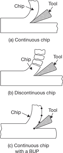
FIGURE 19.1
Types of Chip Formation in Metal Cutting
Continuous Chip: Continuous chip as shown in Figure 19.1 (a), is formed due to:
- Machining of ductile materials.
- Small undercut thickness.
- High cutting Speed.
- Large rake angle of the tool.
- Suitable cutting fluids.
Discontinuous Chip: Discontinuous chip as shown in Figure 19.1 (b), is formed due to:
- Machining of brittle work materials.
- Low cutting speed.
- Small rake angle.
- Large uncut chip thickness.
Continuous Chip with a Built-up (BUP) Edge: Continuous chip with a built-up edge as shown in Figure 19.1 (c), is formed due to:
- Large friction or stronger adhesion between chips and tool face.
- Low rake angle.
- Large uncut chip thickness.
19.3 ORTHOGONAL AND OBLIQUE METAL CUTTING
Orthogonal cutting is a machining process in which the cutting edge of the tool is kept perpendicular to the direction of the tool travel (Figure 19.2). But, in oblique cutting, the cutting edge of the tool is inclined at some acute angle to the direction of the tool travel. There are some fundamental differences in orthogonal and oblique cutting which are mentioned in Table 19.1.
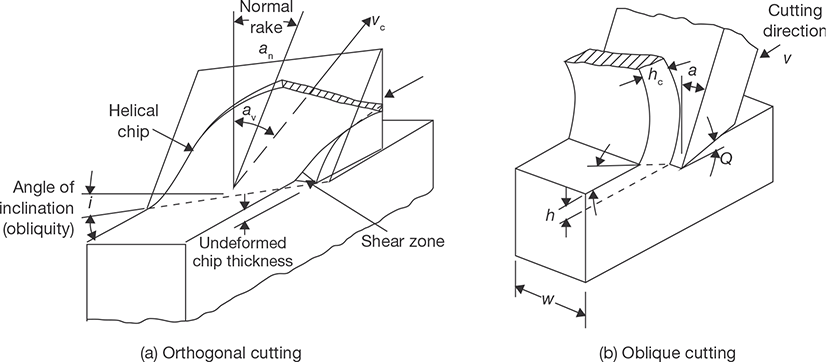
FIGURE 19.2
Schematic View of Orthogonal and Oblique Cutting

19.4 LATHE
Lathe is the oldest machine tool. The entire machine tools are developed from the lathe, therefore, it is also known as the mother of machine tools. A number of cutting operations can be performed on a lathe with or without some attachments. On the lathe, a rotational motion is provided to the job and translational motion is provided to the cutting tool. Lathe machines can be classified on the basis of speed and purposes of applications.
19.4.1 Classification of Lathes
According to the construction and design lathe can be classified as follows:
- Bench Lathe: It is small in size and mounted on a separate table. It has all the attachments, which a larger lathe has. It is used to perform a precise work.
- Speed Lathe: This may be bench type or legs supported lathe. It has no gearbox, carriage, and lead screw. Therefore tool is actuated and fed by hand. This lathe is used for wood turning, polishing and spinning purposes.
- Engine Lathe: This is the most widely used lathe. In early days, during the development phase of the lathe this lathe was driven by the steam engine, therefore named as engine lathe. Nowadays, all the engine lathes have separate engines or electric motors. Various speeds are achieved using cone pulley and gears.
- Tool Room Lathe: This is very similar to engine lathe but equipped with some extra attachments for more accurate and precise works. The usual attachments are taper turning attachment, follower rest, collets, chucks, etc.
- Capstan and Turret Lathes: This is semi automatic type lathe and a wide range of operations can be performed on them. It can hold a large number of cutting tools compared to engine lathe.
19.4.2 Specifications of Lathe
Lathe machine can be specified by following dimensions (Figure 19.3):
- Height of center over bed (A)
- Maximum swing over bed (B)
- Maximum swing over carriage (C)
- Maximum swing in gap (D)
- Maximum length of work (E)

FIGURE 19.3
Specifications of Lathe
19.4.3 Constructional Detail of Lathe
A lathe machine consists of a number of components. These components perform various functions, for example, facilitate variation in speed, hold the cutting tool, rigidly hold the job, provide end support to the job, automatic movement of the tool, etc. A lathe with the nomenclature of various parts is shown in Figure 19.4.
Bed: All the fixed and moving parts of the lathe are mounted on the bed. It is made of cast iron in a single piece, it may be in two or three pieces for large size lathe, which are bolted together. It has v-ways for the collection of chips produced during machining. The carriage of the machine rests over the bed and slides on it. On the top of the bed, there are two sets of guide ways-inner ways and outer ways. The inner ways provide sliding surfaces for the tail stock and the outer ways for the carriage. The guide ways of the lathe bed may be flat and inverted V shape. Generally, cast iron alloyed with nickel and chromium material is used for manufacturing of the lathe bed.
Head Stock: Head stock is the housing of cone pulleys, back gear, main spindle, live center, and feed reverse levers. It provides a driving mechanism to the job and tool post, carriage, apron, etc. The main function of head stock is to transmit power to the different parts of a lathe.
Tail Stock: The function of tail stock is to support the job at the end. It slides over the bed. It may have dead center or live center for point support to the job as per requirement. A tailstock is shown in Figure 19.5.


FIGURE 19.5
Tailstock of a Lathe
For tapping, drilling or boring, a tape or drill/boring tool may be used in place of dead center. The dead center moves forward or backward with the sleeve by rotating the hand wheel manually. Tail stock can be easily set or adjusted for alignment/nonalignment with respect to the spindle center and carries a center called dead center/live center for supporting one end of the work. Both live and dead centers have 60° conical points to fit center holes in the circular job, the other end tapering to allow for good fitting into the spindles. A live center or revolving center is constructed so that the 60° center runs in its own bearings and is used at the non-driven or tailstock end of a machine. A dead center (one that does not turn freely, i.e., dead) may be used to support the workpiece at either the fixed or rotating end of the machine. When used in the fixed position, a dead center produces friction between the workpiece and center, due to the rotation of the workpiece.
Carriage and Tool Post: It provides support to the tool post, cross slide, compound rest, apron, etc. The function of tool post is to hold cutting tool rigidly; tool post moves in the transverse direction on compound rest. The function of swivel plate is to give angular direction to the tool post whereas the function of cross slide is to give the linear motion to the tool by rotating the attached hand wheel. The apron is a hanging part in front of the carriage. It is the housing of gear trains and clutches. It gives automatic forward and reverse motion to the tool.
Legs: The legs provide rigid support to the entire machine tool. Both the legs are firmly secured to the floor by means of foundation bolts in order to prevent vibrations in the machine.
Chucks: The function of the chuck is to hold the job. There may be three-jaw or four-jaw chuck as shown in Figure 19.6. In three-jaw chuck, all the jaws move inwards or outwards simultaneously and there is no problem of centering hence it is also known as universal chuck. Whereas in four-jaw chuck each jaw moves independently. It may accommodate the irregular shape of the job but there is a problem of centering which is to be done manually. A magnetic chuck is also used to hold the job which works on the principle of electromagnetism.
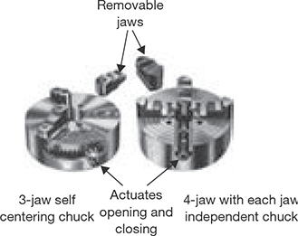
FIGURE 19.6
Three- and Four-jaw Chucks
19.4.4 Power Transmission System in Lathe Machine
Head stock spindle drive system may include stepped or cone pulley drive or all geared head drive. In stepped pulley, the number of speed equals to the number of steps in the pulley. In all geared head drive, total nine various speed can be achieved.

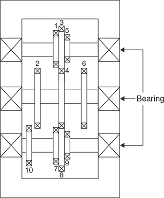
FIGURE 19.8
A Constructional Detail of All Geared Head Drive
Stepped Pulley (Cone Pulley) Drive: V-belt is used to transmit the power from driver shaft to spindle shaft. In 4-stepped pulley drive, four different speed of the head stock can be attained. Spindle speeds are varied in arithmetic progression (Figure 19.7).
Let driver shaft rotates at the speed of N rotation per minute (rpm) and the steps diameters of the pulley are D1, D2, D3, and D4. Driven shaft has pulley of same steps diameters but in reverse order, as shown in Figure 19.10. We know the speed is inversely proportional to the diameter, therefore,
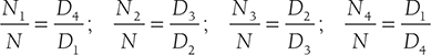
Where N is the speed of driver shaft and N1, N2, N3, N4 are speeds of the spindle shaft. Here D1 < D2 < D3 < D4.
All Geared Head Drive: This drive comprises of nine gears on three shafts. By operating two levers attached to two cluster gears on pulley shaft and head stock main spindle respectively, nine speeds can be obtained. Three gears 2-4-6 are fixed on the intermediate shaft. Spur gear (10) is fixed on the head stock spindle to transmit power to the feed shaft and lead screw. The constructional detail of all geared head drive is shown in Figure 19.8.
The gear combinations for nine different speeds are given below:

where T1, T2, T3, T4, T5, T6, T7, T8, and T9 are number of teeth on gear 1, 2, 3, 4, 5, 6, 7, 8 and 9, respectively.
19.4.5 Cutting Tools Used in Lathe
A number of cutting operations are performed on a lathe machine. Therefore, various cutting tools are used in a lathe such as left hand and right hand turning tools, facing tools, threading tools, parting-off tool, etc., as shown in Figure 19.9.
19.4.6 Types of Operations on Lathe Machine
Following are the various types of operations performed on the lathe machines:
(a) Turning, (b) Threading, (c) Tapping, (d) Drilling and boring, (e) Reaming, (f) Knurling, (g) Facing, (h) Parting, (i) Spinning.
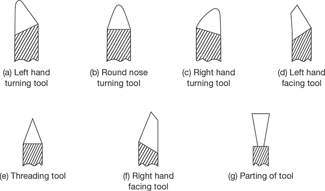
FIGURE 19.9
Various Cutting Tools Used in Lathe

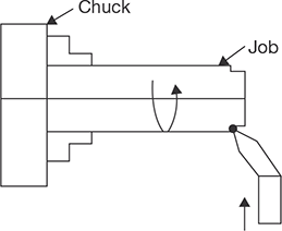
FIGURE 19.11
Face Turning on Lathe
Turning: Turning is a metal removal process in which job is given rotational motion while the cutting tool is given linear (feed and depth of cut) motion. Different types of turning operations are mentioned below:
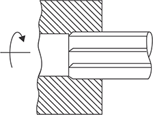
Straight Turning: It is the operation of producing a cylindrical surface of a job by removing excess material. In this operation, the job rotates and the tool is fed longitudinally by giving the desired depth of cut (Figure 19.10).
Face Turning or Facing: It is also known as facing operation. It is the operation of making the ends of a job to produce a square surface with the axis of operation or to make a desired length of the job. In this operation, job rotates and the tool advances in a perpendicular direction to the axis of the job rotation (Figure 19.11).
Shoulder Turning: If a job is turned with different diameters, the steps for one diameter to the other so formed, the surface is known as shoulder turning. There are several types of shoulder turning such as square, radius, beveled, etc., as shown in Figure 19.12. It is also known as step turning.
Eccentric Turning: When a job having more than one axis of rotation, each axis may be parallel with each other but never coincides, turning of different cylindrical surfaces of the job is known as eccentric turning. In Figure 19.13, the job is first turned through centers C1-C1 and then through centers C2-C2.
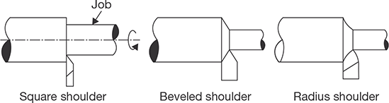
FIGURE 19.12
Shoulder Turning on Lathe


FIGURE 19.14
Taper Turning on Lathe
Taper Turning: Taper turning is an operation in which taper cylindrical surface, i.e., cone type surface is produced as shown in Figure 19.14.
Taper on a cylindrical surface of a job can be produced by the following methods:
Taper Turning by Swiveling Compound Rest: Job rotates on lathe axis and tool moves in the angular path. It can be applied from any angle 0-90 degree, a short length of taper up to 150 mm approximate ![]() It is used for shorter length and steeper angle. Here, D1 and Ds are larger and shorter diameters, and ℓ is the length of the job.
It is used for shorter length and steeper angle. Here, D1 and Ds are larger and shorter diameters, and ℓ is the length of the job.
Taper Turning by Offsetting the Tailstock: Job rotates at an angle to the lathe axis and the tool travels longitudinally to the lathe axis. Any angle 0 to 8°, long job of smaller diameter can be turned by this method. It is also used for internal taper turning.
Taper Turning Attachment: Job rotates on lathe axis and tool moves in guided angular path. Any angle 0–12°, long jobs of steeper angle of taper can be done by this attachment. The guide rail is set as per angle of taper. It is applied for longer jobs of steep angle in mass production.
Taper Turning by a Form Tool: Job rotates on lathe axis and tool moves crosswise direction, perpendicular to the lathe axis. The very small length of taper and any angle 0–90°. The tool itself designed as per requirements. It is used for mass production for Chamfering on bolts, nuts, bushes, etc.
Taper Turning by Combination Fed: Job rotates on lathe axis and tool travels on the resultant path, for any length and any angle. The taper angle is to be determined by trial and error method. It is applied by hand feeds for making the ball of a hammer, by power feeds for production work.
Parting-off (Grooving): It is the operation of cutting-off/grooving a bar after it has been machined to the required shape and size. In this operation, the job is held on a chuck, rotates to the turning speed and the parting-off tool is fed into the job very slowly until the tool reaches to the center of the job. The parting-off operation is shown in Figure 19.15.


FIGURE 19.16
Knurling Operation on Lathe
Knurling: Knurling is the process of embossing, producing a roughened surface on a smooth surface of a cylindrical job to provide effective gripping, for example, thimble and ratchet of micrometer and plug gauge handle. Knurling tools (single, two or three sets of rollers) are held rigidly on tool post, pressed against the rotating (one-third speed of the turning) surface of a job, leaving exact facsimile of the tool on the surface of the job as shown in Figure 19.16.
Thread Cutting
For thread cutting on the lathe, there is a definite relationship between the speeds of the job and tool. The relationship is obtained by gear ratio which selection depends on the pitch of the job, the pitch of the lead screw, number of the start of the thread on the job. Every machine is supplied with a spur gear box (a set of 23 gears) having teeth from 20 to 120 with an interval of 5 and a special gear or transfer gear is of 127 teeth for cutting the metric thread. Two 20 teeth spurs are available. Lead screw has single start thread. The simple process of thread cutting on the lathe is shown in Figure 19.17.

FIGURE 19.17
Thread Cutting on Lathe
Steps for Thread Cutting on Lathe
- Hold the job on the machine and turn up to the major diameter of the thread.
- Choose suitable thread cutting tool.
- Select slower speed of the lathe spindle.
- Calculate the change gear ratio based on the following formula:

- Fix the calculated change gear ratio to the head stock spindle, intermediate shaft and lead screw shaft.
- Choose suitable depth of cut. Three or four cuts are necessary to complete the thread.
- Arrange job and tool proper position and give desired depth of cut.
- Engage half nut with respect to chasing dial according to odd/even threads.
- Allow the movement of the tool up to the portions of the job necessary for thread cutting then lifting the tool from the job.
- Disengage the half nut, move the carriage to the right side up to the position from where the second cut will start. Allowing the second depth of cut again engage the half nut with respect to chasing dial.
Drilling: The operation of producing a circular hole by removing metal by rotation the cutting edges of a drill is known as drilling. But on lathe drill is static and only feed motion is given through the movement of tail stock and rotating motion is given to the job. Metal is removed by shearing and extrusion. Drilled hole will be slightly oversized than the drill used due to the non-alignment of the drill and vibration of the spindle. For producing an accurate hole, the drill bit should be chosen slightly undersize and subsequent reaming or boring operation is essential after drilling. Drilling on the lathe is very easy. The drill bit is held in tail stock in place of dead center and moved in the forward direction applying pressure at the end of the rotating job. Drill moves up to the length of the hole required as shown in Figure 19.18.
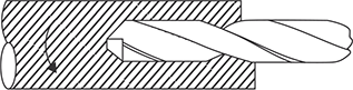
FIGURE 19.18
Drilling on Lathe
Tapping: Tapping is an operation for producing internal thread. A hole of minor diameter is produced in the job by holding the drill tool in tail stock and applying pressure on the rotating job in chuck. After drilling the hole, the tap is held in tail stock and inserted in drilled hole of the rotating job as shown in Figure 19.19.
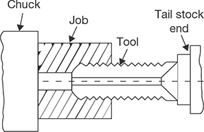
FIGURE 19.19
Tapping on Lathe
Reaming: The operation of finishing and sizing a previously drilled hole using a multi-edges straight cutting tool named as a reamer is known as reaming operation. Very small amount of material (0.4mm) removal is possible by this operation. Reaming operation is on lathe is very similar to drilling on the lathe as shown in Figure 19.20.
Boring: The operation of enlarging and finishing a previously drilled hole throughout its length by means of an adjustable single edge cutting tool named as boring tool is known as boring. Boring on the lathe is also very similar to drilling but this process is used to enlarge the drilled hole as shown in Figure 19.21.
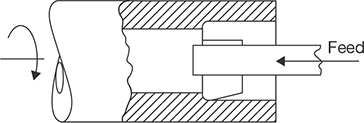
FIGURE 19.21
Boring on Lathe
Spinning: Spinning is a process to produce a circular homogeneous pot or house hold utensil. In this operation, the sheet metal job is held between a former attached with headstock spindle and the tail stock center and rotates at high speed with the former. The long round nose forming tool fixed rigidly on special tool post presses the job on the periphery of the former as shown in Figure 19.22. Thus the job is deformed exactly in the shape of former and the operation is known as spinning. It is chip-less machining process.

FIGURE 19.22
Spinning on Lathe
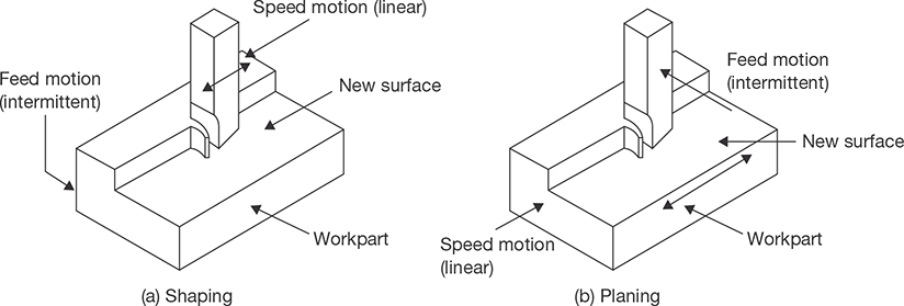
19.5 SHAPER, SLOTTER, AND PLANER
Shaper and planer are very old machine tools. They are used to produce a plane surface, inclined surface, and slots. But due to consumption of excess time, they are replaced by milling machines in large production. In a shaper, the cutting tool is provided reciprocation motion and job is provided only feed motion. Normally, forward stroke is a cutting stroke and backward or reverse stroke is idle stroke. During the backward stroke, the job is given feed motion. In a planer, the table job is given reciprocating motion and the tool is given feed motion. Planer is most suitable for the larger job which cannot be accommodated on the shaper.
19.5.1 Shaping and Planing
Shaping and planning are the oldest methods of machining. They are seldom used in production and have been replaced by milling and broaching. The major difference between these two processes is that, in shaping the reciprocating or cutting motion is provided to the tool and the feed is given to the workpiece, whereas in planning, it is just opposite (Figure 19.23). A single point cutting tool is used in both processes. The cutting takes place only in the forward stroke; the feed is given to the workpiece in return stroke. This operation is neither efficient nor economical. Shapers are more suitable for smaller workpieces than the planers. In addition to plain flat surfaces, the shapes most commonly produced on the shaper and planer include grooves, T-slot, and dovetails.
19.5.2 Constructional Detail of Shaper
Constructional detail of shaper is shown in Figure 19.24. There are following parts of the shaper machine.
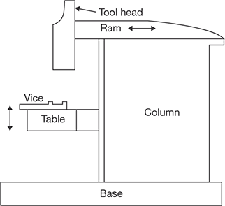
FIGURE 19.24
Constructional Details of Shaper
Base: Base is made of gray cast iron to absorb the vibration and it is bolted to shop floor.
Column: It is the housing of ram, quick return mechanism, and table. A ram reciprocates on the top of the column through two machined guide-ways and table can move up and down through cross-rail on the front of the vertical face of the column.
Table: It is a cast iron body, provided with T-slots to clamp the job, fixtures, etc., the table can move up and down and also it can be tilted in universal type shaping machine.
Ram: It carries a tool head on its front end. It reciprocates on horizontal guide-ways of the machine on the top of the column across the work. The motion of the ram is obtained by quick return mechanism. It cuts only in the forward stroke and moves faster in the backward or return stroke.
Tool Head: It is fixed at the front end of the ram. It consists of tool post, clapper box, down feed screw. Tool slide can be swiveled for the shaping of bevels, angular cuts, etc. The clapper box hinges on a pin in order to allow the tool to swing up during the return stroke. Down feed screw may be operated by hand or power for required depth of cut and down feed cutting.
Cross-rail and Saddle: Cross-rail slides up and down for positioning of the table over the front vertical ways of the column. The work table is bolted on the saddle and saddle is also mounted on the cross-rail. The work table along with the saddle can be moved horizontally by the table cross-feed screw.
19.5.3 Slotter Machine
Vertical shaper machine is also known as slotter machine in a workshop but the fundamental difference between vertical shaper and slotter machine is that the frame of the vertical shaper is fixed and cannot be tilted whereas the frame of slotter machine can be tilted at any angle. The small angle may be given to tool to the vertical shaper but if the larger deviation is required then slotter machine is used. The ram of slotter machine reciprocates in the vertical direction. It is used to cut the slot vertically. The construction detail and driving mechanism are very similar to shaper machine.
Applications of Slotter Machine
Slotter machine is applied:
- To machine the vertical surface.
- To machine the inclined surface.
- To cut the internal and external gear teeth.
- To machine the surfaces that are difficult to machine on the shaper.
- To machine the blind hole.
19.5.4 Crank and Slotted Arm Quick Return Mechanism
Rotary motion of the bull gar is converted into a reciprocating motion of the ram through the crank and arm. The cutting is done in the forward stroke and the return stroke is idle. The time of return stroke is reduced to compress the total machining time which is known as quick return mechanism. The quick return mechanism may be attained by any of the methods—Whitworth quick return, crank and slotted arm, and hydraulic mechanism. In this text, crank and slotted arm mechanism is discussed as it is very simple in construction and operation.
The schematic diagram of the crank and slotted arm mechanism is shown in Figure 19.25 (a). The driving pinion, which receives power from electric motor directly or over head line shaft, drives the bull gear either directly or through back gears. The crank pin may be adjusted by a hand wheel operating through suitable gears for specified length of the stroke. The slotted link is provided at its lower end, while the upper fork end is connected with the moving block. Crank pin is the connector between the crank gear and slotted link. The rotary motion of the crank gear transmits the rocking movements of the slotted link by the crank pin within the slot. This rocking movement of the slotted link is communicated to the reciprocating movement of the ram through the moving block which is locked with ram screw.
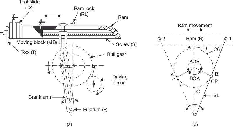
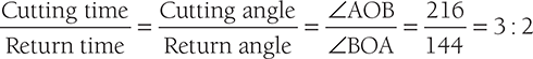
It is seen from the block diagram in Figure 19.25 (b) that the path traveled by the crank pin during the forward motion is much more than the backward motion. Since ∠BOA = 144° and ∠AOB = 360° − 144° = 216°
19.5.5 Specification of Shaper
The shaper can be specified in the following terms:
- Length of stroke (300 mm).
- Maximum horizontal travel of table (350 mm).
- Maximum vertical travel of table (365 mm).
- Maximum distance from table to ram.
- Maximum vertical travel of tool slide (117 mm).
- Length and width of table top (300 × 250 mm).
19.5.6 Constructional Detail of Planer
A constructional detail of the planer is shown in Figure 19.26. There are following components of the planer:

FIGURE 19.26
Constructional Details of the Planer
Bed: Bed is a cast iron structure; it is very large and heavy and supports whole structure of the machine over it.
Table: Table is made of cast iron. At its top, it carries longitudinal T-slots and holes to accommodate the clamping bolts and other devices. Under the table, chip pockets are provided integrated with it for collecting and removing the chips. On its side, the table carries adjustable stops to reverse its motion at the end of each stroke. At its both ends, it carries a trough to collect the chips.
Housing or Columns: The vertical members situated on both side or a single side of the planer is housing or column. Inside them, they carry the different mechanism for power transmission to the upper part of the machine, from the main drive. At their front, they are very accurately machined to form vertical ways along which the cross-rail slides up and down where side tool-heads are used; they also slide vertically along the same guide ways.
Cross-rail: It connects two housings and provides additional rigidity to the machine. It can slide up and down on the guideways provides on the column; there is the provision of guideways on the front side of the Crossrail to move the two tool head horizontally from one end to another end of the table.
Tool Heads: Maximum four tool heads can be fitted in a planer, two in the vertical position on cross rail and two in the horizontal position on columns. All of them can be used at the same time.
19.5.7 Fast and Loose Pulleys Driving Mechanism of Planer
A driving mechanism of a planer consists of an electric motor situated over the housing. The motor shaft is coupled with a counter shaft. The counter shaft, at its extreme end, carries two driving pulleys; one for the open belt and other for cross the belt. The main driving shaft is provided below the bed. Its one end passes through the housing and carries a pinion, which meshes with the rack provided under the table of the machine. The other end of the shaft carries two pairs of pulleys; each pair consists of a fast pulley and a loose pulley. One of these pairs is connected to one of the driving pulleys by means of an open belt and the other to the second driving pulley by means of crossed belt. A speed reduction gear box is mounted on the main driving shaft and same is incorporated between the pinion and the pairs of driven pulleys. The driving mechanism is shown in Figure 19.27.
One set of the above pulleys is used for the forward motion and another set for the backward motion of the table. The cross belt is used for the forward motion and open belt is used for the backward motion. The driving pulley on the counter shaft for the cross belt is smaller than the pair of the fast and loose pulleys for the same. While the driving pulley on the driving pulley on the driving shaft for open belt is bigger than the pair of fast and loose pulley on the same. This arrangement is provided for slow forward stroke and fast backward stroke.
The pulleys are so arranged that when the cross belt is on fast pulley, i.e., in the forward stroke, the open belt will be on the loose pulley and its reverse will take place during the return stroke. The relative shifting of the belt may take place automatically at the end of each stroke, without stopping the machine; a belt shifter and its operating lever are provided on the machine. Trip dogs are mounted at both ends of the table. At the end of each stroke, these dogs strike against the operating lever alternately and the belt shifted accordingly. Thus, table movement is reversed automatically.
19.5.8 Specifications of Planer
Planer can be specified in the following ways:
- Horizontal distance between two housings.
- Vertical distance between table top and cross-rail.
- The maximum length of the stroke.
19.5.9 Difference between Shaper and Planer
Table 19.2: Difference between Shaper and Planer

19.6 DRILLING MACHINE
Drilling machine is one of the important machine tools in a machine shop. It is mostly used to produce a hole in the solid material. In a drilling, the hole is generated by cutting edges of rotating cutting tool known as drill bit which exerts large force on the workpiece fixed on the table. Drilling, boring, counter-boring, counter sinking, reaming, tapping and spot facing operations can be performed on this machine.
19.6.1 Driving Mechanism in Drilling Machine
The power from the electric motor is transmitted to drill spindle pulley through V-belt. There is a provision of the key way on drill spindle to slide the stepped V-pulley. When the drill is required to feed into the work, it is pressed against the work by means of feed handle. As the handle is rotated, pinion rotates and rack moves longitudinally and hence the spindle and drill on the machine; drill rotates at very high speed to attain the required cutting speed. The complete driving mechanism is shown in Figure 19.28.
FIGURE 19.28
Driving Mechanism of a Drilling Machine
19.6.2 Drill Bit
The different part of the drill bit is shown in Figure 19.29.
Flute: the helical groove in the drill body is known as a flute. Its functions are to carry the chips, admit the coolant, make the chips to curl, and provide the cutting edges on the point.
Point: It is conical part of the drill; cutting lips are ground on the point.
Body: The part of the drill that is fluted and relieved is known as the body.
Tang: The flattened end of the taper shank is known as tang. It helps to remove the drill from socket or sleeve from the spindle without injuring the shank.
Dead Center: The point at which the two lips are properly ground and meet is known as dead center.
Lips: The cutting edges of a drill are known as lips. Both lips should have equal length, same angle of inclination and correct clearance.
Margin or Land: The narrow surface along the groove that determines the size of the drill and keeps the drill aligned is known as margin or land.
Web: The backbone of the drill of the narrow section between the flutes is known as the web.
FIGURE 19.29
Drill Nomenclature
Heel: The edge which is formed by the intersection of the flute surface and the body clearance is known as the heel.
Some Important Angles on a Drill
Rake Angle: It is also known as helix angle. The angle between a plane passing through drill axis and leading edge of the land is known as rake or helix angle. It varies from 0° to 48°. Higher values are suitable for softer materials and lower values are suitable for harder materials.
Point Angle: It is also known as cutting edge angle. It is the angle included between the two opposite lips of a drill, measured in a plane containing the axis of the drill and both the lips. The most common value of the angle is 118°. Smaller point angle is suitable for brittle material and a larger one for harder and tougher materials.
Chisel Edge Angle: The obtuse angle formed between the lip and the chisel edge is known as chisel edge angle. The greater the angle larger will be clearance. It ranges from 120° to 135°.
19.6.3 Specifications of a Drilling Machine
Drilling machines are specified in the following ways:
- The maximum size of the drill in mm.
- Table size.
- The maximum spindle travel.
- Range of spindle speed in rpm.
- Power input of the machine in H.P.
19.6.4 Operations Performed on Drilling Machine
Drilling: The operation of producing a circular hole by removing metal by rotation the cutting edges of a drill is known as drilling. Metal is removed by shearing and extrusion (Figure 19.30). Drilled hole is slightly oversized due to non-alignment of the tool and vibration of the spindle. For producing an accurate hole, the drill bit selected is slightly smaller than the hole-diameter required. After producing the hole reaming is required for finishing.
FIGURE 19.30
Drilling
Reaming: It is an operation to produce a finished hole after drilling. Since the material removal rate in reaming is very less (0.4 mm) therefore it is rarely used for enlarging the hole. Reamer has straight teeth which is given a rotational motion similar to drilling. The reaming operation is shown in Figure 19.31.

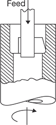
FIGURE 19.32
Boring

FIGURE 19.33
Counter boring

FIGURE 19.34
Counter Sinking
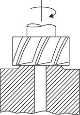
FIGURE 19.35
Spot Facing
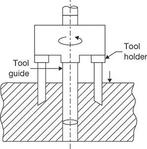
FIGURE 19.36
Trepanning
Boring: It is an operation to enlarge the drilled hole. It has single cutting point cutter as shown in Figure 19.32. In Boring, the material removal rate is larger than that of drilling. Therefore for enlarging purpose boring tool is used in place of large diameter drill bit.
Counter Boring: The operation of enlarging the end of a hole cylindrically, as a recess for a bolt head, is known as counter boring. The counter boring process is shown in Figure 19.33.
Counter Sinking: The operation of making a cone shape enlargement of the end of a hole, as for the accommodating the screw head, is known as counter sinking (Figure 19.34).
Spot Facing: The operation of squaring and smoothing the surface around a hole, as for the seat for a nut or head of a bolt, etc., is known as spot facing (Figure 19.35).
Trepanning: The operation of producing a large hole (diameter over 50 mm) by removing metal along the circumference of a hollow cutting tool, which enters the small previously drilled hole to produce the larger hole concentric is known as trepanning (Figure 19.36). It is used for the diameter more than the capacity of the particular machine and where hole depth is much more in comparison with normal work.
19.6.5 Advanced Types of Drilling Machine
Radial Drilling Machine
Radial drilling machine is a heavy duty machine. It consists of a vertical column supporting a horizontal arm on which drill spindle can move in a radial direction. The arm can be raised or lowered and swung around any position over the work. Two electric motors are used as shown in Figure 19.37, one used to provide movement to the arm and other is used to drive spindle of the drilling machine.
Gang Drilling Machine
Gang drilling machine is used for mass production where a number of drilling operations are to be performed in sequence. Each drill head can be equipped with different types of drill bits. There may be 2 to 10 spindles. The construction of gang drilling machine is shown in Figure 19.38.
Multi-spindle Drilling Machine
A multi-spindle drilling machine has a number of spindles driven by a single motor. All the spindles holding the drills can be used simultaneously. It can produce a number of parallel holes simultaneously. It is employed for a light work. The construction of multi-spindle drilling machine is shown in Figure 19.39.

FIGURE 19.37
Radial Drilling Machine
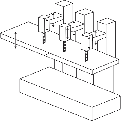
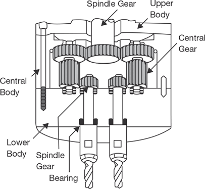
FIGURE 19.39
Multi-spindle Drilling Machine
19.7 BORING
Boring machine is one of the versatile machine tools. This is most suitable for machining of a large and heavy workpiece in mass production, for example, a cylinder of I.C. engines, machine housing, engine frame, etc. This machine can perform all the operations which can be done on the drilling machine. But this machine is heavier than the drilling machine.
19.7.1 Specification of Boring Machines
Main specification of a boring machine is designated by the following terms:
- Type of machines.
- Maximum size of boring spindle diameter (50–320 mm).
- Maximum spindle travel in horizontal and vertical direction.
- Maximum travel of the table in longitudinal and crosswise directions in mm.
- Range of spindle speeds in rpm.
- Power of the motor in H.P.
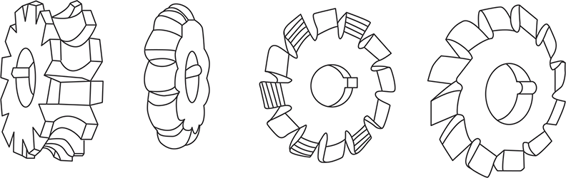
19.8 MILLING MACHINES
Milling is a metal cutting process in which different shapes and sizes of the surface are generated by cutting action of rotating multipoint cutter fixed on a periphery of a wheel and feed is given to the work. The shaft on which milling cutter is mounted is known as arbor, this may be horizontal or vertical. On the basis of the position of the arbor, a milling machine can be divided into two classes—horizontal and vertical milling machines as shown in Figure 19.40. The size of the milling machine is generally denoted by the dimension of the table. Different manufacturers denote these sizes by different numbers such as 0, 1, 2, 3, 4, 5, 6, etc. Each of these numbers indicates a particular standard size adopted by the manufacturer.
The various types of milling machines are column and knee type, fixed bed type, planer type, production milling machine, and special purpose milling machine.
19.8.1 Constructional Detail of Milling Machine
Base: The base is foundation part of a milling machine. It is made of gray cast iron. It absorbs vibrations and supports column, table arbor, etc.
Column: It is the main casting mounted on one side of the base. This is box shaped and fitted with gearing arrangement for different spindle speeds and table feeds (Figure 19.40).
Knee: It is rigid gray cast iron part that supports and provides adjustment for the height of the table, operating by the table elevating screw and slides up and down on the vertical dovetail guide ways of the column. It carries the table feed mechanism and controls to feed in longitudinal, cross, vertical and rotational, etc., either by hand power or machine power.

FIGURE 19.40
Horizontal and Vertical Milling Machines
Table: Table is the part on which job is mounted either directly by a clamp or by a fixture. It rests on the saddle and travels longitudinally. The table travel is limited by the adjustable stops in either direction during power feeding. In the case of universal milling machine, there is an arrangement of the table to swivel horizontally around the center of its base.
Feed Gear Box: The variation of power feed to all movement is achieved through the feed gear box. The power from the feed gear box is transferred to the knee by a telescopic shaft. The number and amount of feed depending on the gearing arrangements in the feed gear box.
Spindle: The spindle is mounted on the upper part of the column. It receives power from the motor through belts, gears, clutches, etc., and can be rotated at different speeds by the step-cone-pulley drive or gear drive.
Arbor: The arbor is an extension of the spindle on which various cutters are mounted. The arbor is set in spindle cone (Morse taper cone) and tightened by draw bolt held in position by a bush nut.
19.8.2 Basic Milling Operations
Up Milling and Down Milling: The horizontal milling is divided into two groups—up milling and down milling. If the direction of cutting and feed are opposite to each other, the milling is known as up milling, and if the directions of both are the same, the milling is known as down milling as shown in Figure 19.41. In down milling, there is a tendency of the job being dragged into the cutter, therefore, up milling is safer and is commonly used. However, down milling results in better surface finish and longer tool life. In down milling, the chip thickness starts at maximum and decreases to its minimum value at the end of the cut where tooth leaves the work. In up milling, the chip thickness starts at zero and increases to its maximum value at the end of the cut where the tooth leaves the work. Cutting forces tend to lift the workpiece up from the table, hence the name up milling.
Slab Milling: Slab milling, also called peripheral milling or plane milling generates flat surfaces by using the teeth located on the periphery of the cutter body as shown in Figure 19.42. The axis of cutter rotation is parallel to the workpiece surface to be machined. The diameter and width of the cutter depend on a part is to be slab milled.
Generally, helical teeth cutter is selected for slab milling. Less force is required; vibration and chatter are reduced; and a better quality of surface finish is produced with a helical tooth cutter than with a straight tooth cutter. This is possible because of the fact that the helical teeth are continuously engaged in comparison with the intermittent cutting action of straight tooth cutter. Milling cutters up to 18 mm wide generally have straight teeth and cutters over 18 mm wide usually have helical teeth. The angle of helix ranges from 45° to 60° or steeper. Straight cutters are used for light duty and helical for heavy duty.

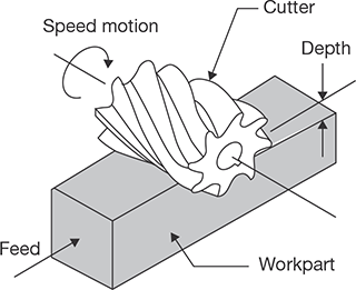
FIGURE 19.42
Slab Milling
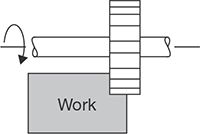
FIGURE 19.43
Side Milling
Side Milling: Side milling uses side milling cutters similar to plain milling cutters. However, in addition to teeth around the periphery, other cutters are formed on one or both sides as shown in Figure 19.43. The teeth may be either straight helical. Most of the cutting is done by the teeth around the periphery.
The side cutting teeth cut the side of the workpiece. Side mills are not recommended for milling slots because of their tendency to mill wider.
End Milling: End milling is a process of machining horizontal, vertical, angular and irregular shaped surfaces. The cutting tool is called an end mill as shown in Figure 19.44. End mills are coarse tooth cutters and made of high-speed steel or have carbide inserts. They are subjected to severe torsion and bending stresses in use. These limit the size of cut that can be taken. With a cut equal to the full width of the cutter, the maximum recommended a depth of cut in 0.6D, D being the diameter of the end mill. If, however, the cutting action is the cleaning up of the edge of a component, with the cut only 10% of the diameter, the depth can be increased to 1.5D. This process can be used to mill grooves, slots, keyways, and large surfaces. It is also widely used for profi le milling in die making.
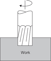
FIGURE 19.44
End Milling

Face Milling: Face milling is an extension of end milling where the cutter has large diameter with several cutting teeth as shown in Figure 19.45. The cutter diameter is usually 6 inches or more. The teeth are beveled or rounded at the periphery of the cutter.
Face milling cutters are made of high-speed steels, cast alloys or carbides and are heavy-duty cutters. Heavy cuts, coarse feeds, and high cutting speeds are essential. The cutter is mounted on a spindle having an axis of rotation perpendicular to the workpiece surface; Face milling is used to produce a flat surface and has a wide variety of applications.
Gang Milling: It is the milling operation which involves the use of a combination of more than two cutters, mounted on a common arbor, for milling a number of flat horizontal and vertical surfaces of a workpiece simultaneously as shown in Figure 19.46. This combination may consist of only side milling cutters or plain milling cutters or both.

FIGURE 19.46
Gang Milling
Straddle Milling: It is a milling operation in which a pair of side milling cutters is used for machining two parallel vertical surfaces of a workpiece simultaneously as shown in Figure 19.47.

FIGURE 19.47
Straddle Milling Cutter
Form Milling: This milling process is employed for machining those surfaces which are of irregular shapes. The cutter used, called a form milling cutter, will have the shape of its cutting confirming to the profile of the surface to be produced. Form milling cutter is shown in Figure 19.48.
Profile Milling: It is the operation in which the profile of a template or the shape of the cavity of a master-die is duplicated on the work surface. The movement of the cutter is guided by a tracer control unit which carries a contact finger. This finger (stylus) run in contact with the outline to be duplicated and the tracer mechanism guides the tool movement accordingly.
19.8.3 Nomenclature of Milling Cutter
Radial Rake Angle: It is the angle between the flute face and a radial reference plane XX drawn from the cutter axis to the cutting edge. Positive radial rake angle is used for highspeed cutters and to cut the soft materials like aluminum. Negative rake angle is used for high-speed milling with carbide tipped cutter and to cut the hard materials.
Relief Angle: It is the angle between the land and a tangent to the cutter from the tip of the tooth. It eliminates the tendency of the teeth to rub the work. The angle may vary from 3 to 5 degrees, with higher angles 8° to 10° for smaller diameter and soft work materials.
Clearance Angle: It is the angle between the back of the tooth and a tangent to the cutter from the tip of the tooth (Figure 19.49).
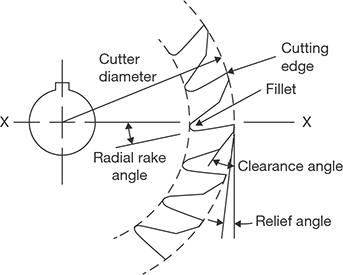
FIGURE 19.49
Nomenclature of Milling Cutter
19.9 GRINDING MACHINES
Grind means to wear or to abrade by friction. The grinding process may be defined as the removal of a layer of a work piece by rotating an abrasive wheel. It is very similar to milling process as each abrasive particle at the periphery of the grinding wheel acts like a tooth of the milling cutter, but the orientation of the abrasive particles are random in the grinding wheel. The chips formed in this process are very small and the geometry of the chips can be seen with the help of a microscope.
19.9.1 Grinding Wheel Specification
The application of the different types of grinding wheels depends on the properties of the work materials and the type of applications. In the alphanumeric system, a grinding wheel can be specified by 7-terms as shown in Figure 19.50.
Code Number: It is optional and used by manufacturers to indicate exact type of abrasive.
Abrasive Types: An abrasive is a hard material, which can be used to cut or wear away other materials. The major types of abrasives used in the grinding wheel are natural abrasives and artificial abrasives. Natural abrasives include a sand tone or solid quartz, Emery (50–60% crystalline Al2O3 plus iron oxide), Corundum (75–90% crystalline Al2O3 plus iron oxide), diamond, and garnet whereas artificial abrasive include A: Al2O3; C: SiC; D: Diamond. Other abrasives are boron carbide and cubic boron nitride may be used as artificial abrasives.
Grit Size: Grit size is used to indicate the grain size that is reciprocal of grit size in inch. For example, if grit size is 36 then the grain size will be equal to 1/36 inch. Using the larger grains, material removal capacity will be the more, but the quality of the surface finish will be poor. The grain size is determined primarily by the surface quality requirements. Grit size is defined in terms of a number as given below:
Grade: The grade indicates the strength of the bonding material. A hard wheel means strong of the bonding and the abrasive grains can withstand large forces without getting dislodged from the wheel and in the case of a soft wheel, the situation is just reverse. If the work material is hard and wheel used is also hard, the grains wear out easily and the sharpness of the cutting edges quickly lost. This is known as glazing of the wheel. A glazed wheel cuts less and rubs more making the process inefficient. To avoid this problem, a soft wheel is used for harder materials so that the grains, which lose the sharpness, get easily dislodged as the machining force on the individual grain increases. The layers of new grains are exposed, maintaining the sharpness of the wheel.

FIGURE 19.50
Grinding Wheel Specification
If the work material is soft, a hard wheel should be employed since the problem of glazing will be absent and a longer wheel life will be achieved. The grade of the grinding wheel is indicated in terms of capital alphabetic letters as:
Soft: A-H; Medium: J-P; Hard: Q-Z.
Structure: The grinding wheel is similar to a milling cutter with a very large number of randomly oriented teeth. Therefore, it must have voids to allow spaces for the chips. If the voids are too small for the chips, the chips stay in the wheel blocking the voids. This is known as wheel loading, which causes inefficient cutting. If the voids are too large, again the cutting action is inefficient since there will be less cutting edges. In an open structure, the grains are not too densely packed and in a wheel, with a closed structure, the grains are tightly packed. For grinding of ductile work materials, larger chips are produced and to reduce the tendency of wheel loading, an open structure is preferred. In the case of hard and brittle work materials, a closed structure is selected. The structure depends on the required grade and also, on the nature of cut. For a rough cut, an open structure is more suitable. The structure is represented by some numbers as:
Dense: Less than 10; Open: 11–16.
Bond: It represents the binding materials use of to bind the abrasive particles. Some alphabetic letter is used to indicate the Bond as—Vitrified-V; Resinoid-B; Silicate-S; Rubber-R; Shellac-E.
Vitrified Bond: It is a clay bond, reddish brown in color. The base material is feldspar, which is fusible clay. The exact proportion of the refractories and flux are added to it and mixed thoroughly. The mixture, together with the abrasive grains, is fed into revolving drums containing water, where all the constituents make together to form a pest. The pest is then placed in a mold to get the shape of a wheel and air dried at room temperature. Thus, the wheel becomes enough hard. Now, the wheel is fed into a kiln and allowed to remain for a few days. The inside temperature is being about 1260°C, the process is known as fusing and it provides the uniform distribution of bond throughout the wheel. It is used for the speed of 32 m/sec.
Silicate Bond: In this bond, silicate of soda is mixed with the abrasive grains and the mixture is packed and rammed in a metal molds. After drying for several hours, the wheels are baked at 260°C for 1–3 days. Silicate wheels are milder than those made by other processes and wear away more rapidly. They are suitable for grinding the edges of cutting tools where the heat must be kept to a minimum. This process is also recommended for very large wheels since they have little tendency to crack or warp in the baking process. The hardness of the wheel is controlled by the amount of silicate of soda.
Shellac Bond: The abrasive grains are first coated with shellac by mixing in a steam heated mixer. The material is then placed in heated steel molds and rolled or pressed. Finally, the wheels are baked for a few hours at a temperature around 300°F. This bond is adapted to thin wheels, as it is very strong and has some elasticity. Shellac bonded wheels are also used for grinding cam shafts and other parts where a high polished is desired. Other uses are sharpening large saws, cutting of operation, and finishing large rolls. They can run safely in the water, but use of the oil or caustic soda should be avoided.
Rubber Bond: Pure rubber with sulfur as a vulcanizing agent is mixed with the abrasive by running the material between heated mixing rolls. It is rolled to a fixed thickness and the wheel are cut out with a proper shaped die and then vulcanized under pressure. A very thin wheel can be made by this process because of the elasticity of the material. Wheels having this bond are used for high speed grinding as 45–80 m/sec. They are used a great deal as snagging wheels in foundries and also cutting off wheel.
Bakelite or Resinoid Bond: In this process, the abrasive grains are mixed with a synthetic resin powder and a liquid solvent. This plastic mixture is then molded to proper shape and baked in an electric oven at 200°C for one-half to three days. This bond is very hard and strong, and wheels made by this process can be operated at speed around 50–80 m/sec. They are used for general purpose grinding and are widely used in foundries and billet shops for snagging purposes because of their ability to remove metal rapidly.
Oxychloride Bond: It is a mixture of oxide and chloride of magnesium and setting takes place in the cold state. The process of wheel manufacture is similar to the above two but no heating and subsequent cooling is required on account of the cold setting property. Aging is, however, necessary so that the bonded wheel gets adequate hardness. The bond provides a cool cutting action. But, grinding is usually done dry as it is very susceptible to the action of conventional coolants and, therefore, the full use of the cutting capability of the wheel cannot be taken.
Manufacturer’s Record: Optional for manufacturer’s code number.
19.9.2 Methods of Grindings
A number of grinding methods are used according to shape and size of the jobs. Some of the commonly used methods can be given below as:
Cylindrical Grinding: It means grinding of outside cylindrical and tapered surface.
Internal Grinding: It means a method of grinding the internal surfaces of cylindrical or tapered holes.
Surface Grinding: It is a method of grinding the internal surfaces of cylindrical or tapered holes.
Face Grinding: It is a method of grinding vertical flat surfaces. The wheel spindle can be horizontal or vertical.
Infeed or Plunge Cut Grinding: It is also a method of grinding very short work pieces. It involves the use of grinding wheel having its face wider than the length of the surface to be ground and feeding the same into the work with no traversing motion of it.
Form Grinding: It is a method of producing formed surface through grinding. The wheel face is given the desired shape by dressing and then fed on the work surface, as in the case of thread grinding and the gear teeth grinding.
Centerless Grinding: It is a method of grinding external cylindrical surfaces, in which work is supported by a regulating wheel, a grinding wheel, and a work rest blade.
Off Hand Grinding: It is a rough grinding method in which the work is held in hand and pressed against the rotating grinding wheel. This method is commonly used for grindings of such items in which accuracy and surface finish are not of primary importance, such as in sharpening cutting edges of chisels, etc.
Sharpening Cutting Tools: Several cutting tools, including single point tools, milling cutters, drills, reamers, hobs, correct geometry, restore lost geometry, and sharpen their cutting edges.
Creep Feed grinding: It is a method in which a soft grinding wheel is used. The wheel revolves in position while the work is fed past the revolving wheel at a very slow speed. Multi passes are avoided and the entire depth of material is removed in a single pass. Ample amount of coolant usually sulfurized oil, under pressure, is used in the process. The dressing of the grinding wheel is continuously done during the process, for which a diamond coated dressing wheel (roll) is mounted above the grinding wheel.
Types of Grinding Machines
Broadly, the Grinding Machine can be Classified as: Rough grinders and Precision grinders. The main aim with rough grinders is to remove more materials than the quality of surface finish. Therefore, it is also known as non-precision grinders. These grinders include—Bench, pedestal or floor grinders, Swing frame grinders, Portable and flexible shaft grinders, and Belt grinders.
Precision Grinders: There are a large number of precision grinders, but in this text, we will discuss only cylindrical type grinders only for the basic information.
19.9.3 Cylindrical Grinders
The principle of operation of cylindrical grinding is shown in Figure 19.51. It consists of holding fixtures rotating about its axis and feeding a fast revolving grinding wheel against the same. If the work surface is to be ground is longer than the face width of the grinding wheel, the work is traversed past the wheel or wheel past the work. In the case of the larger face width of the wheel than the work length, the wheel may be fed in with no traversing movement of it or that the work. This is known as plunge grinding. There are three types of cylindrical grinders—plain cylindrical grinders, plain surface grinders, universal cylindrical grinders, and centerless grinders.

19.9.4 Plain Cylindrical Grinders
In these grinders, the workpiece is held between two centers, i.e., headstock and tailstock. The rotating wheel is traversed across the face of the rotating grinding wheel as shown in Figure 19.52. At the end of each traverse, wheel is fed into the work by an amount equal to the depth of cut. Tailstock and headstock both can be moved along the table to suit the work. The table is usually made of two parts—the upper table carries the tailstock, headstock, and the workpiece and can be swiveled in a horizontal plane to a maximum of 10° on either side, along with the circular ways provided on the lower table. This enables grinding of tapered surfaces. The lower table is mounted over horizontal guide ways to provide longitudinal traversed to the upper table, and hence the work. Table movement can be both by hand as well as power.
19.9.5 Plain Surface Grinders
A plane surface grinder produces a flat surface by reciprocating the job and rotating the abrasive wheel as shown in Figure 19.53. It is similar to a planer. It consists of a movable table, which can move in longitudinal as well as in transverse direction. The table is equipped with the magnetic chuck to hold the job. The grinding wheel is mounted on a horizontal or vertical spindle depends on the needs. The grinding wheel and the spindle are mounted on a column, which allows it to be raised or lowered. The feed motion is given to the job as in shaper and planer. The rotating motion is given to the abrasive wheel.

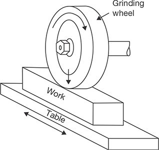
FIGURE 19.53
Plane Surface Grinders
19.9.6 Universal Cylindrical Grinders
There are following extra facilities in the universal cylindrical grinder than the plain cylindrical grinder:
- Its headstock can be made to carry alive or dead spindle, as desired, the former being needed when the work is held in a chuck.
- The headstock can itself be swiveled in a horizontal plane.
- Its wheel head can be raised or lowered and can also be swiveled to either side by 90° to grind taper surfaces having large taper angles.
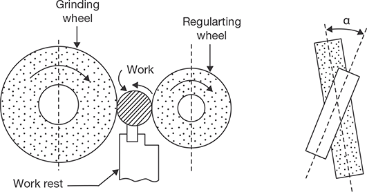
19.9.7 Centerless Grinders
These grinders are also a type of cylindrical grinders but the principle of centerless grinding differs from center type grinding in that the work, instead of being mounted between centers, is supported by a combination of a grinding wheel, a regulating wheel, and a workrest blade as shown in Figure 19.54. The principle of centerless grinding is used for both the external grinding as well as internal grinding. Many hollow cylindrical and tapered workpieces, like bushes, pistons, valves, tube, and balls, etc, which are the best ground on centerless grinders.
Advantages of Grinding
- It is the only method of cutting such materials as hardened steel parts requiring hard surfaces are first machined to shape while the metal is in an annealed state and then only a small amount of excess material is removed by the grinding operations.
- It produces good finishing that is extremely smooth and, hence, very desirable at contact and bearing surfaces. As the wheel has a considerable width, there are no marks as result of feeding it across the work.
- Grinding can finish work to very accurate dimensions in a short time. Since only a small amount of material is removed, the grinding machines require a close regulation of the wheel, and it is possible to hold work to a fraction of a thousandth of an inch with the considerable case.
- Very little pressure is required in this process, thus permitting its use in very light work that would otherwise tend to spring away from the tool. This characteristic permits the use of magnetic chucks for holding the work in many grinding operations.
- Abrasives have very high hardness, are less sensitive to heat compared to other materials and can sustain high-temperature.
RECAP ZONE
Points to Remember
- The removal of extra material from a metal surface by shearing or cutting action is known as machining or metal cutting.
- In metal cutting the line generated by the cutting motion is called generatrix and the line formed by feed motion is called directrix.
- Back rake angle is the angle between the face of the tool and a line parallel with the base of the tool measured in a perpendicular plane to the side cutting edge.
- Side rake angle is the angle between the base of the tool shank and the face of the tool measured in a plane perpendicular to the plane through the side cutting edge and at the right angle to the base.
- The angle between the planes of the end flank immediately below the end cutting edge and a line perpendicular to the base and right angle to the axis is known as end relief angle.
- The angle between the planes of the side flank immediately below the side cutting edge and a line perpendicular to the base along the axis is known as side relief angle.
- The angle between the plane of the end cutting edge and the plane perpendicular to the axis, both right angles to the base, is known as an end cutting edge angle.
- The angle between the plane of the side cutting edge and the plane perpendicular to the axis, both right angles to the base, is known as a side cutting edge angle.
- The nose radius has a major influence on surface finish. A sharp point at the end of a tool leaves a groove on the path of cut.
- Orthogonal cutting is a machining process in which the cutting edge of the tool is kept perpendicular to the direction of the tool travel.
- In oblique cutting, the cutting edge of the tool is inclined at some acute angle to the direction of the tool travel.
- On the lathe, a rotational motion is provided to the job and translational motion is provided to the cutting tool.
- Turning is a metal removal process in which job is given rotational motion while the cutting tool is given linear (feed and depth of cut) motion.
- The operation of producing a circular hole by removing metal by rotation the cutting edges of a drill is known as drilling.
- The operation of finishing and sizing a previously drilled hole using a multi-edges straight cutting tool named as reamer is known as reaming.
- The operation of enlarging and finishing a previously drilled hole throughout its length by means of an adjustable single edge cutting tool named as boring tool is known as boring.
- In a shaper, cutting takes place by reciprocating tool over the job.
- In a planer, cutting takes place by reciprocating the job under the tool.
- The operation of producing a large hole (diameter over 50 mm) by removing metal along the circumference of a hollow cutting tool, which enters the small previously drilled hole to produce the larger hole concentric is known as trepanning.
- Radial drilling machine consists of a vertical column supporting a horizontal arm on which drill spindle can move in a radial direction.
- Gang drilling machine is used for mass production where a number of drilling operations are to be performed in sequence. Each drill head can be equipped with different types of drill bits.
- A multispindle drilling machine has a number of spindles driven by a single motor. All the spindles holding the drills can be used simultaneously. It can produce a number of parallel holes simultaneously.
- Milling is a metal cutting process in which different shapes and sizes of the surface are generated by cutting action of rotating multipoint cutter fixed on a periphery of a wheel and feed is given to the work.
- If the direction of cutting and feed are opposite to each other, the milling is known as up milling, and if the directions of both are the same, the milling is known as down milling.
- Slab milling, also called peripheral milling or plane milling generates flat surfaces by using the teeth located on the periphery of the cutter body.
- Side milling uses side milling cutters similar to plain milling cutters. However, in addition to teeth around the periphery, other cutters are formed on one or both sides.
- End milling is a process of machining horizontal, vertical, angular and irregular shaped surfaces.
- Face milling is an extension of end milling where the cutter has large diameter with several cutting teeth.
- Gang milling is the milling operation which involves the use of a combination of more than two cutters, mounted on a common arbor, for milling a number of flat horizontal and vertical surfaces of a work-piece simultaneously.
- Straddle milling is a milling operation in which a pair of side milling cutters is used for machining two parallel vertical surfaces of a workpiece simultaneously.
- Form milling is employed for machining those surfaces, which are of irregular shapes. The cutter used, called a form milling cutter, will have the shape of its cutting confirming to the profile of the surface to be produced.
- Profile milling is the operation in which the profile of a template or the shape of the cavity of a masterdie is duplicated on the work surface.
REVIEW ZONE
Multiple-choice Questions
- The cutting edge of the tool is perpendicular to the direction of tool travel in:
- Orthogonal cutting of metal
- Oblique cutting of metal
- Both
- None of the above
- The cutting edge of the tool is inclined at an angle less than 90° to the direction of tool travel in:
- Orthogonal cutting of metal
- Oblique cutting of metal
- Both
- None of the above
- In metal cutting operations, discontinuous chips are produced while machining:
- Brittle materials
- Ductile materials
- Hard materials
- Soft materials
- In metal cutting operations, continuous chips are produced while machining:
- Brittle materials
- Ductile materials
- Hard materials
- Soft materials
- Size of shaper is specified by:
- The length of stroke
- The size of the table
- The maximum size of the tool
- H.P. of motor
- Size of planer is specified by:
- The length of stroke
- The size of the table
- The maximum size of the tool
- H.P. of motor
- A standard ground drill has a point angle of:
- 90°
- 100°
- 118°
- 120°
- For harder materials, point angle of drill:
- Increases
- Decreases
- Kept at 118°
- None of the above
- One of the important parameters of lathe specification is:
- Swing over bed
- Swing over tool post
- The distance between centers
- Horse power
- Centering can be done most accurately on:
- Four-jaw chuck
- Three-jaw chuck
- Lathe dog
- Collet
- In gang milling:
- Spot facing is the operation of:
- Enlarging the end of a hole cylindrically
- Cone-shaped of the enlargement of the end of a hole
- Smoothing and squaring the surface around a hole
- Sizing and finishing a hole
- counter sinking is the operation of:
- Enlarging the end of a hole cylindrically
- Cone-shaped of the enlargement of the end of a hole
- Smoothing and squaring the surface around a hole
- Sizing and finishing a hole
- Reaming is an operation of:
- Enlarging the end of a hole cylindrically
- Cone-shaped of the enlargement of the end of a hole
- Smoothing and squaring the surface around a hole
- Sizing and finishing a hole
- Drilling is a type of:
- Oblique cutting
- Simple cutting
- Uniform cutting
- Orthogonal cutting
- Drill diameter is measured over the:
- Main body
- Margins at the drill point
- Heel
- Lips
- The chip is cut off at thinnest place and then chip thickness increases along chip length in:
- Up milling
- Down milling
- End milling
- Climb milling
- Maximum friction is caused in:
- Up milling
- Down milling
- End milling
- Climb milling
- The cutting force tends to lift the work piece in:
- Conventional milling
- Down milling
- Climb milling
- Form milling
- Advantages of conventional (up) milling is:
- Older machines have backlash in their lead screws can be used
- On sand casting cutter is not damaged
- Better finish obtained on steel but not on aluminum
- All the above
- Disadvantage of conventional milling is:
- Chip gets picked up and carried around the cutter, thereby spoiling the finish
- On steel, the finish may be slightly rougher
- The machine must have zero backlashes or there will be chatter as the cutter tries to pull the table faster than the feed rate.
- All the above
- Grinding is a process of removing materials by:
- Cutting action
- Rubbing action
- Wearing action
- Polishing action
- After dressing operation, a grinding wheel is required to adjust the:
- Guard
- Eye shield
- Tool rest
- All of the above
- In the case of cylindrical grinding, the depth of cut normally used for roughing is:
- 0.05 mm
- 0.01 mm
- 0.005 mm
- 0.001 mm
- In the case of cylindrical grinding, the depth of cut normally used for roughing is:
- 0.05 mm
- 0.01 mm
- 0.005 mm
- 0.001 mm
Fill in the Blanks
- 26. In metal cutting operation, chips are formed due to ____ of metal.
- 27. In center lathe, cutting tool is fed in ____ directions with reference to the lathe axis.
- 28. The work piece cannot be held in a lathe chuck can be clamped to a ____ mounted on a headstock spindle.
- 29. The cutting action of a shaper occurs only on the ____ stroke of the ram.
- 30. Quick return motion is incorporated in a shaper, a planer and ____.
- 31. A slotter can be considered as a ____ shaper having only vertical movement of ____.
- 32. Any number of equal division can be obtained on milling machine by ____.
Answers
Theory Questions
- * Enumerate the operations which can be performed on lathe machine.
- Explain the various techniques to perform a taper turning on a lathe.
- * What are the differences between shaper and planer?
- Explain quick return mechanism used in shaper with neat sketch.
- * Explain the working of radial drilling machine with a neat sketch.
- Explain the stepped cone pulley drive in the lathe.
- * Differentiate up milling and down milling.
- Draw a neat diagram of the horizontal and vertical milling machine.
- Explain feed mechanism used in a drilling machine.
- What are the various types of milling operations, explain with the neat sketch?
- Write short notes on counter boring, counter sinking, spot facing, and trepanning.
- What do you mean by grinding? How it differs from milling?
- Draw a neat sketch of the drill bit and explain all the terminology used for nomenclature.
- Discuss the method of nomenclature of grinding wheel.
- Explain the various methods of grinding.
- Explain the method of centerless grinding.
- Discuss the working of the cylindrical grinding machine with a neat sketch.
- Discuss the working of plane grinding machine with a neat sketch.
- Discuss the surface finishing methods with various applications.
- * Write the difference between shaper and slotter machines?
- * Explain the different types of grinding process with sketches.
- * Draw a well-labeled neat sketch of lathe machine and state the functions of its different parts.
- * Explain with figure taper turning with compound slide swiveling method.
- * With the help of a neat sketch, explain the working of a universal milling machine.
- * Explain with figure working principle of centerless grinding machine.
- * Explain any two milling operations.
- * With a neat sketch, explain the principle and operation to produce a “taper’ on a lathe by tail stock set over method.
- * Differentiate between the cross slide and compound slide.
- * List any four differences between the horizontal milling machine and vertical milling machine.
- * Differentiate between (i) Counter sinking and counter boring and (ii) Reaming and Boring.
- * Explain plane milling, end milling, slot milling, with a neat sketch.
- * Sketch a radial drilling machine and explain its working.
- * Draw the neat sketch of the horizontal milling machine and explain parts.
- * List the four elements which specify the size of the Lathe.
- * With a neat sketch, explain the following lathe operations.
- * Facing, Cylindrical turning, Knurling, Thread cutting.