
Chapter 9
Endpoint Registration
This chapter covers the following topics:
SIP Registration to the Cisco Unified Communications Manager: This topic will explain how to configure settings on UC phones and Telepresence endpoints for SIP registration to the Cisco Unified Communications Manager.
SIP Registration to the Cisco Expressway Core: This topic will explain how to configure settings on Telepresence endpoints for SIP registration to the Cisco Expressway Core.
H.323 Registration to the Expressway Core: This topic will explain how to configure settings on Telepresence endpoints for H.323 registration to the Cisco Expressway Core.
For any old-school voice engineers who might be reading this book, and to the general audience of people who may or may not understand this simple truth, the Cisco Unified Communications approach to provisioning and controlling phones has been to keep the intelligence in the call control systems, such as the Cisco Unified Communications Manager, and keep the phones dumb. This is a practice taken from tradition telephony over analog or digital circuit-switched systems and continues to be practiced cross-vendor in the IP telephony world. Cisco has added some intelligence to its UC phones, such as with Dial Rules, but on the norm, it continues to keep the intelligence at the hub of the call control systems. This idea has changed with Telepresence endpoints. There is a shared intelligence between the endpoint and the call control system, both in function and capabilities. What you will discover throughout this chapter is the much more advanced configuration options that exist on Telepresence endpoints versus their counterparts, UC phones. Topics discussed in this chapter include the following:
SIP Registration to the Cisco Unified Communications Manager
PoE
CDP and LLDP-MED
DHCP
TFTP
SIP Registration
ITL, CTL, and CAPF
SIP Registration to the Expressway Core
DHCP versus Static IP
Manual Configuration of SIP Settings
H.323 Registration to the Expressway Core
H.323 Aliases
Manual Configuration of H.323 Settings
This chapter covers the following objectives from the Cisco Collaboration Core Technologies v1.0 (CLCOR 350-801) exam:
1.1.g Security (certificates, SRTP, TLS)
1.3.g Certificates
2.4 Deploy SIP endpoints
“Do I Know This Already?” Quiz
The “Do I Know This Already?” quiz allows you to assess whether you should read this entire chapter thoroughly or jump to the “Exam Preparation Tasks” section. If you are in doubt about your answers to these questions or your own assessment of your knowledge of the topics, read the entire chapter. Table 9-1 lists the major headings in this chapter and their corresponding “Do I Know This Already?” quiz questions. You can find the answers in Appendix A, “Answers to the ‘Do I Know This Already?’ Quizzes.”
Table 9-1 “Do I Know This Already?” Section-to-Question Mapping
Foundation Topics Section |
Questions |
|---|---|
SIP Registration to the Cisco Unified Communications Manager |
1–6 |
SIP Registration to the Expressway Core |
7–8 |
H.323 Registration to the Expressway Core |
9–10 |
Caution
The goal of self-assessment is to gauge your mastery of the topics in this chapter. If you do not know the answer to a question or are only partially sure of the answer, you should mark that question as wrong for purposes of the self-assessment. Giving yourself credit for an answer you correctly guess skews your self-assessment results and might provide you with a false sense of security.
1. How much power can be supplied to a phone using Cisco prestandard PoE?
5.5W
7W
14.5W
15W
2. When you are configuring a VLAN on a switchport, which of the following commands will configure the phone to use IEEE priority tagging for voice traffic and to use the default native VLAN to carry all traffic?
802.11n
802.1q
802.1p
802.3af
3. When the CUCM is used as the DHCP server, how many devices can it support?
100
500
1000
10,000
4. The Maximum Serving Count service parameter specifies the maximum number of requests that can be concurrently handled by the TFTP server on the CUCM. What is the default value of this parameter?
2500
5000
7500
10,000
5. Which SIP registration header field contains the address of record of the person responsible for the registration?
Request URI
To
From
Call-ID
6. Which of the following are considered Security By Default mechanisms on the CUCM? (Choose two.)
ITL
CTL
CAPF
TLS
TLS Verify
TVS
7. Which of the following is a required setting when configuring static network information on an endpoint?
Gatekeeper address
DNS
TFTP
Default gateway address
8. Which of the following commands is required before the SIP endpoint can register to the Cisco Expressway when configuring the CE endpoint using CLI?
xConfiguration NetworkServices SIP Mode: On
xConfiguration Provisioning Mode: VCS
xConfiguration Provisioning Mode: TMS
xConfiguration SIP DisplayName: name
9. Which of the following aliases is acceptable as an H.323ID?
555 - 1212
John Hancock
John 1212
John@Hancock
10. An administrator is using the CLI to configure a DX80 endpoint to register to a Cisco Expressway Core. While configuring the alias, the administrator configures an H.323 ID when it should not have been. How can the administrator remove the H.323 ID using the CLI?
xconfiguration h323 h323alias remove all
xconfiguration h323 h323alias id: leave blank
xconfiguration h323 h323alias id: delete
xconfiguration h323 h323alias id: “”
Foundation Topics
SIP Registration to the Cisco Unified Communications Manager
Chapter 5, “Communication Protocols,” provided a high-level overview of the SIP registration process to the Cisco Unified Communications Manager. The basic elements of the whole SIP registration process can be summarized in the following order:
The endpoint obtains power.
The endpoint loads the locally stored image file.
The endpoint communicates with the switch using CDP or LLDP-MED.
The endpoint negotiates DHCP with the DHCP server.
The endpoint is issued CTL (optional) and ITL certificates from the Cisco Unified Communications Manager.
The endpoint communicates with the TFTP server.
The endpoint registers to the CUCM.
Although many moving parts must be configured for this registration process to work, after each component is configured, very little must be done on the end user’s part for devices to register to the Cisco Unified Communications Manager. This process is designed to ease the registration process and also allow engineers to mass-deploy tens of thousands of endpoints at the same time. When the components involved with this process are deployed properly, little to no configuration needs to be set up on the endpoint itself. You can just power the system on and let these services provision all the various settings on the phones. The following sections describe how to configure these various components so that this provisioning process will operate correctly.
PoE
An endpoint can receive power in two ways: Power over Ethernet (PoE) or through a power cube, which is the traditional cable you plug into the system and the wall outlet. All Telepresence endpoints require a power cube to be used, with the one exception of the Cisco Telepresence SX10. All of the Cisco UC phones can support either a power cube or PoE. Because PoE is the expected form of power, none of the UC phones come standard with a power cube; this component must be ordered separately. A big difference between some of the phones as related to PoE is the type or class of PoE supported.
PoE, also referred to as inline power, is the capability for the LAN switching infrastructure to provide power over a copper Ethernet cable to an endpoint or powered device. Cisco developed and first delivered this capability in 2000 to support the emerging IP telephony deployments. IP telephones, such as desktop PBX phones, need power for their operation, and PoE enables scalable and manageable power delivery and simplifies deployments of IP telephony. Because these early PoE-capable devices were basic phones without a lot of features added to them, the power requirements were pretty low. Cisco’s prestandard PoE, which was called inline power, supported only 7 watts (7W) of power. The IEEE quickly recognized the contribution Cisco made to the IT industry and began working on a standardization for PoE. The first standard for PoE that could be used industrywide and applicationwide was 802.3af. With the advent of 802.3af came many more devices that could support PoE, including wireless access points, video cameras, point-of-sale devices, security access control devices such as card scanners, building automation, and industry automation, to name a few.
The IEEE 802.3 standard outlines two types of devices: power sourcing equipment (PSE) and powered devices (PDs). Power sourcing equipment provides power to the powered devices. A PSE can support power delivery Type A, Type B, or both. Type A involves sending power over two unused pairs or wires on a CAT3, CAT5, or CAT5E cable. This works well for links up to 100 Mbps, but Gigabit Ethernet uses all the copper pairs in a CAT5E cable. Therefore, Type B uses a “phantom power” technique to send power and data over the same pairs. When an Ethernet device is connected to a PSE, the PSE initially applies a low voltage (2–10 volts) to sense whether the device is a PoE PD. If it is, the PD will send a return current back to the PSE, and 48 volts will be supplied so the device can power on and load its locally stored image file. If no return current is sent back to the PSE, the device connected is not a PD, such as a computer connected over Ethernet, and no power will be supplied. The maximum power that a PSE will supply down an Ethernet cable using 802.3af is 15 watts; however, due to possible losses on a long cable, the maximum power that a PD can receive down an Ethernet cable using 802.3af is 12.95 watts.
The IEEE 802.3at standard, also known as PoE+, supports up to 25.5W of power on the ports, allowing devices that require more than 15.4W to power on when connected to the PoE+ ports. Several Cisco switches support 802.3at PoE, including the Meraki MS series switches. Based on the classification currently used by the device, the Meraki MS switch will classify the device as a Class 0, 1, 2, 3, or 4 type device and apply the proper standards-defined behaviors to the port. Table 9-2 describes these five classifications on Meraki switches.
Table 9-2 Meraki Switch PoE Classifications
Class |
Usage |
Classification Current [mA] |
Power Range [watt] |
Class Description |
|---|---|---|---|---|
0 |
Default |
0–4 |
0.44–12.94 |
Classification unimplemented |
1 |
Optional |
9–12 |
0.44–3.84 |
Very low power |
2 |
Optional |
17–20 |
3.84–6.49 |
Low power |
3 |
Optional |
26–30 |
6.49–12.95 |
Mid power |
4 |
Valid for 802.3at (Type 2) devices, not allowed for 802.3af devices |
36–44 |
12.95–25.50 |
High power |
When a PD is connected to an 802.3at switch port, a lower power voltage can be supplied because 802.at is backward compatible. There is a limit to how much power may be drawn across wires before electrical damage occurs due to overheating within connectors and cable bundles. There is also a concern over signaling interference with this protocol. Some of these issues are resolved by using multiple pairs to deliver the necessary power. At the moment, 802.3at limits the number of pairs that can carry power to two. A current limit of 720mA is being considered, allowing 29.5W per pair; however, the IEEE is working on Draft 3.0 to reduce this to 600mA giving 25W per pair, or 50W per device. The IEEE is also looking at mandating Category 5 cables and later to be used with 802.3at so that you do not have to worry about supporting Category 3 cabling. With 802.3at the maximum power that can be delivered to the application is 50W. The first detection pulse, or classification pulse, from the PSE will be the same as 802.3af, to which the 802.3af PDs will respond normally. A second PoE Plus pulse then will cause an 802.3at PD to respond as a Class 4 device and draw the Class 4 current. After this has happened, there will be a data exchange where information such as duty-cycle, peak, and average power needs will be shared. Other features to be catered for in 802.3at include dynamic power assignment, leading to more efficient power supply designs and consequent power saving.
For a Cisco UC phone to receive PoE from a switch, it is essential to connect the patch cable coming from the switch into the appropriate port on the phone. You should be aware of three switch ports in Cisco phones. There are two physical switch ports on the back of each phone. One of the switch ports is called a network port, and this is the port to which the patch cable that connects back to the switch should be connected. The second physical port on the back of a Cisco phone is called the PC port, and it is the port that a computer can be connected to in order to receive network access. PoE will not be supplied to the phone if the network cable from the switch is connected to the PC port, nor will the phone be able to communicate with the switch. These two physical interfaces are easy to recognize because there is a graphic below each port to describe that port’s purpose. The computer port has the graphic of a computer monitor, and the network port graphic displays three squares interconnected with lines, signifying the network. The third port on a Cisco phone that you should be aware of is a virtual port located in the phone’s software, which bridges between the computer port and the network port. The phone uses this port to control how packets are marked for the purpose of quality of service (QoS) before they are sent to the switch. PoE promises to create a new world of networked appliances as it provides power and data connectivity over existing Ethernet cables. Table 9-3 identifies the three PoE types discussed in this section. Bear in mind that Cisco has not created or sold prestandard PoE devices since the late 2000s. The information on prestandard PoE is for comparison purposes only.
Table 9-3 Three PoE Types Supported on Cisco Switches
Prestandard Inline PoE |
802.3af PoE |
802.3at PoE+ |
|---|---|---|
Cisco Proprietary |
IEEE standard |
Backward compatible with 802.3af; PoE+ just adds an additional class of power to the 802.3af standard |
10/100 only |
15.4W per port |
30W per port |
7W per port |
Compatible with Gigabit Ethernet |
Relatively new; currently only Cisco is shipping PoE+ phones |
Incompatible with all non-Cisco devices that accept Power over Ethernet |
PoE devices are not compatible with Cisco prestandard PoE; the power negotiation process is completely different |
|
Cisco PoE switches are backward compatible with prestandard PoE |
||
Enough power for most IP phones and wireless access points from all manufacturers |
No settings need to be configured on a Cisco phone to enable PoE. These settings are hard-coded into the phone itself. Most Cisco PoE-capable switches come preconfigured to support PoE as well; however, some settings on a Cisco switch can be configured to disable or enable PoE on certain ports and even boost the power capabilities on specific ports. The following examples illustrate how to configure PoE on a Cisco Catalyst 4500 series switch. Depending on the model number you are configuring, the commands you use might vary slightly. You can enter the following commands into a Cisco switch to enter configuration mode and configure PoE on a specific switchport:
Switch# configure terminal

Switch(config)# interface {fastethernet|gigabitethernet}
(slot/port)

Switch(config-if)# power inline {auto[max milli-watts] | never |
static [max milli-watts]}

Switch(config-if)# end

Switch# show power inline {fastethernet|gigabitethernet} slot/port
An example of the preceding configuration could be as follows:
Switch# configure terminal

Switch(config)# interface fastethernet 0/1

Switch(config-if)# power inline auto 15.4

Switch(config-if)# end

Switch# show power inline fastethernet 0/1
As you can see from the preceding example, you can configure three settings on a switchport for PoE: auto, static, and never. The auto setting is the default value, and this setting allows the supervisor engine on the switch to direct the switching module to power up the interface only if the switching module discovers the phone and the switch has enough power. This mode has no effect if the interface is not capable of providing PoE. The static setting is recommended on high-priority PoE interfaces. The supervisor engine will pre-allocate power to the interface, even when nothing is connected, guaranteeing that there will be power for the interface. If the switch does not have enough power for the allocation, the command will fail. The supervisor engine directs the switching module to power up the interface only if the switching module discovers the powered device. Both of these modes allow you to specify the maximum wattage that is allowed on the interface. If you do not specify a wattage, the switch will deliver no more than the PSE hardware-supported maximum value. The never setting will disable PoE on that particular switchport. This setting is typically used when the interface is intended to be used only as a data interface. The supervisor engine never powers up the interface, even if an unpowered phone is connected. This mode is needed only when you want to make sure power is never applied to a PoE-capable interface. The switch can measure the actual PoE consumption for an 802.3af-compliant PoE module and displays this in the show power inline module command from the privileged EXEC mode.
One other command worth knowing can boost the power on a specific PoE port if not enough power is available: power inline delay shutdown. You might use this command when a prestandard PoE switch is being used to try powering up an 802.3af phone. You also can use this command on an 802.3af switch trying to power up an 802.3at device. However, it is important to understand that when this command is used, you are essentially “borrowing from Peter to pay Paul,” as the saying goes. Power is being taken from another switchport to supply extra power to that particular port being configured. If you use this command, you will not be able to support as many phones on that switch as it was originally designed to support. The command you can use from the configuration mode prompt is as follows:
Switch(config-if)# power inline delay shutdown 20 initial 300
The power inline delay shutdown command configures the port to delay shutting down. This command is useful when a phone requesting more power than the port is originally designed to support would normally go into a cyclical reboot. The initial time period—in this example, 20 seconds—begins when the IEEE-compliant powered device is detected by the switch. If link-down occurs on the connected device during the initial time period, the shutdown time, initial 300, determines how long the switch continues to provide power to the device.
CDP and LLDP-MED
The next step in the registration process to the Cisco Unified Communications Manager, after the phone has powered on and loaded the locally stored image file, is to communicate with the switch. Two protocols can be used for this type of communication: Cisco Discovery Protocol (CDP) and Link Layer Discovery Protocol-Media Endpoint Discovery (LLDP-MED).
CDP is a proprietary protocol that will work only when a Cisco device is communicating to a Cisco device, such as a Cisco phone communicating with a Cisco switch.
If either one of the devices, the phone or the switch, is not a Cisco product, the LLDP-MED protocol will need to be used instead. Several LLDP protocols are available, but LLDP-MED is specifically designed for voice and video communication. Now that it has been established that communication must occur between the phone and the switch, exactly what information is being exchanged is equally important to understand.
A PSE has a PoE “power budget,” which is simply the total power the switch can supply down Ethernet cables. Each time a PD is plugged into the PSE, the PSE subtracts the PD’s maximum power usage from its power budget. If the power budget is all used up, and another PD is connected, that PD will not receive any power. To avoid this problem, 802.3af specifies a method whereby a PD can indicate to the PSE what its maximum power usage will be, by indicating that it complies with one of four “power classes” specified in the standard. For example, if a PD indicates that it complies with power class 2, the PSE knows that it only has to subtract 3.84 watts from its power budget for that PD, thus leaving more power budget for other PDs. In this manner, after the phone powers on, the phone is capable of sending to the switch the required amount of power needed to sustain its core systems. CDP, or LLDP-MED, is the mechanism used to communicate these power adjustments to the switch.
Before the phone obtains its IP address, the phone must also determine which VLAN it should be in by means of the CDP communication that takes place between the phone and the switch. This communication allows the phone to send packets with 802.1Q tags to the switch in a “voice VLAN” so that the voice data and all other data coming from the PC behind the phone are separated from each other at Layer 2. Voice VLANs are not required for the phones to operate, but they provide additional separation from other data on the network. Voice VLANs can be assigned automatically from the switch to the phone, thus allowing for Layer 2 and Layer 3 separations between voice data and all other data on a network. A voice VLAN also allows for a different IP addressing scheme because the separate VLAN can have a separate IP scope at the Dynamic Host Configuration Protocol (DHCP) server. Applications use CDP messaging from the phones to assist in locating phones during an emergency call. The location of the phone will be much more difficult to determine if CDP is not enabled on the access port to which that phone is attached. There is a possibility that information could be gathered from the CDP messaging that would normally go to the phone, and that information could be used to discover some of the network. As mentioned before, not all devices that can be used for voice or video with Cisco Unified Communications Manager are able to use CDP to assist in discovering the voice VLAN. Third-party endpoints do not support CDP. To allow device discovery when third-party devices are involved, you can use LLDP-MED. This protocol defines how a switch port transitions from LLDP to LLDP-MED if it detects an LLDP-MED-capable endpoint. Support for both LLDP and LLDP-MED on IP phones and LAN switches depends on the firmware and device models. To determine if LLDP-MED is supported on a particular phone or switch model, you can check the specific product documentation, release notes, and whitepapers.
VLANS can be configured on specific switchports as a Voice VLAN ID (VVID) or as a data VLAN, or both as a voice and data VLAN. Video will typically use the VVID along with audio. It is not necessary to create a separate voice and video VLAN. Because VLANs will be used to communicate the Layer 2 class of service (CoS) to the phone, it is important to also set up CoS tagging on the switch for specific VLANs. CoS and QoS will be discussed in more depth in Chapter 13, “Layer 2 and Layer 3 QoS Parameters.” The following commands outline how to configure VLANs on the switchports and enable CoS. There are several ways this can be done, and the commands may vary depending on the switch being used. These examples are based on current Cisco Catalyst Switch series.
Switch# configure terminal

Switch(config)# vlan number

Switch(config-vlan)# name name

Switch(config-vlan)# exit

Switch(config)# interface {fastethernet|gigabitethernet}
(slot/port)

Switch(config-if)# mls qos trust cos

Switch(config-if)# switchport voice {detect cisco-phone
[full-duplex] | vlan {vlan-id | dot1p | none | untagged}}

Switch(config-if)# end

Switch# show vlan
Issuing the configure terminal command allows you to enter the configuration mode.
Next, you can create a VLAN using the vlan number command and assign a name to the VLAN for a description.
After exiting VLAN configuration mode, you issue the interface {fastethernet| gigabitethernet} (slot/port) command to enter the interface configuration mode. Next, you issue the mls qos trust cos command so that this switchport will trust the CoS-to-QoS mapping embedded in the switch. Then you enter the switchport voice {detect cisco-phone [full-duplex] | vlan {vlan-id | dot1p | none | untagged}} command. The detect part of the command will configure the interface to detect and recognize a Cisco IP phone. The cisco-phone is the only option allowed when you initially implement the switchport voice detect command. The default is no switchport voice detect cisco-phone [full-duplex]. The full-duplex command is optional. You can configure the switch to accept only a full-duplex Cisco IP phone. This setting is highly recommended because you do not want voice or video traffic to use half-duplex. Calls will consume twice the bandwidth, and connections will be spotty at best. The vlan vlan-id command will configure the phone to forward all voice traffic through the specified VLAN. By default, the Cisco IP phone forwards the voice traffic with an IEEE 802.1Q priority of 5. Valid VLAN IDs are 1 to 4094. The dot1p command will configure the phone to use IEEE 802.1p priority tagging for voice traffic and to use the default native VLAN (VLAN 0) to carry all traffic. Alternatively, the none command will allow the phone to use its own configuration to send untagged voice traffic. Another alternative is the untagged command, which will configure the phone to send untagged voice traffic. Using none or untagged is not recommended for voice traffic.
You type end to exit configuration mode and then issue the show vlan command to verify the VLAN configuration. The following example shows how these commands should appear:
SW1(config)# vlan 200

SW1(config-vlan)# name VVID

SW1(config-vlan)# exit

SW1(config)# Interface fastethernet 0/1

SW1(config-if)# mls qos trust cos

SW1(config-if)# switchport voice vlan 200

SW1(config-if)# end
As an alternative to the switchport voice vlan 200 command, you could use switchport voice detect cisco-phone full-duplex or switchport voice vlan 802.1p. The 802.1p will tag voice traffic with a CoS priority of 5 but use the default VLAN to send traffic. The detect command will send untagged traffic to the switch. Neither one of these options is ideal in a voice or video deployment, which is why the example uses the voice vlan command. In the preceding example, only the voice VLAN was applied to the switchport. Both the voice VLAN and the data VLAN can be applied to the switchport as another option for VLAN configuration. The phone will then use these VLANs to tag all communication originating from the phone with the voice VLAN, and all information originating from a connected computer with the data VLAN. The following example demonstrates how this might look on a switchport:
SW1(config)# vlan 200

SW1(config-vlan)# name VVID

SW1(config-vlan)# exit

SW1(config)# vlan 100

SW1(config-vlan)# name Data

SW1(config-vlan)# exit

SW1(config)# Interface fastethernet 0/1

SW1(config-if)# switchport mode access

SW1(config-if)# switchport access vlan 100

SW1(config-if)# switchport voice vlan 200

SW1(config-if)# end
A computer connected to the phone will normally send packets as untagged. The command switchport mode access will force the port into access mode. The phone will tag computer traffic as data and will tag phone traffic as voice (or video when applicable). Then the command switchport access vlan 100 is used to identify that vlan100 should be used for access tagging of all data traffic originating from the computer. The command switchport voice vlan 200 is used to identify that vlan200 should be used for tagging all voice and video traffic originating from the phone. If CoS Priority 5 should be used for Layer 2 QoS, you will still need to add the command mls qos trust cos, as mentioned previously. When third-party phones are being used, two VLANs on a single switchport may not work for appropriate tagging. LLDP-MED and most other vendor phones do not support this feature.
VLAN discovery is automatic on all Cisco IP phones and Telepresence endpoints, so no settings have to be configured on these devices for VLAN tagging to occur. However, some circumstances may prevent the phone or endpoint from discovering the VLAN. Therefore, you can manually configure a VLAN on a phone or endpoint. The following information on how to configure VLAN settings manually on a Cisco phone is applicable to the 7800 and 8800 series phones. These settings also are available on other Cisco phones, but the menu options to get to these settings may be different.
Step 1. Press the Settings button on your phone. This is the button with the gear icon.
Step 2. Use the circular navigation button on the phone to choose the Admin Settings menu option, or select the number associated with the menu option using the numeric keypad on the phone.
Step 3. Choose the Network Setup menu option in the same manner as above.
Step 4. In the next set of menus that appear, choose Ethernet Setup. There are several menu options under Ethernet Setup.
Step 5. Scroll down to the Operational VLAN ID field. This field is not configurable from the user interface but will display the Voice VLAN ID if one was provided from the switch.
Step 6. If the Operational VLAN ID field is blank, you will need to configure the Admin VLAN ID field with the appropriate VLAN ID.
Step 7. The PC VLAN field is another field that is not configurable from the user interface, unless the Admin VLAN ID was configured first. It will display the data VLAN ID if one was provided from the user interface. Otherwise, you will need to configure one.
Step 8. Press the Apply softkey to save the configured settings. Figure 9-1 illustrates these menu options under the Ethernet Configuration menu.
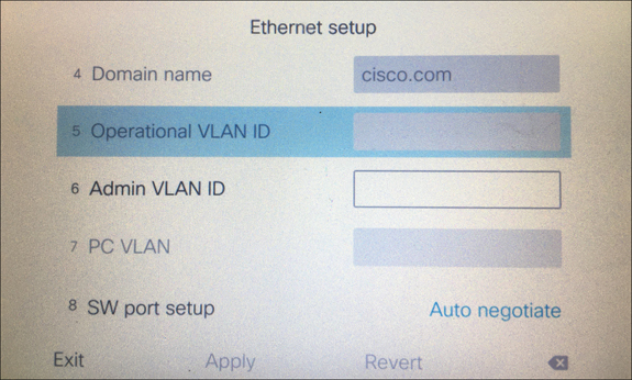
Figure 9-1 Ethernet Configuration Menu Options on Cisco 7800 and 8800 Series Phones
VLAN settings can also be configured on a Cisco CE software-based endpoint. It is important to note here that CE software-based endpoints have auto VLAN discovery enabled by default, but TC software-based endpoints do not. When CE endpoints are registering to a Cisco Unified Communications Manager, no settings have to be preconfigured on the endpoint for that endpoint to register. However, with legacy TC endpoints, you may have to preconfigure some settings on the endpoint before the endpoint can register to the Cisco Unified Communications Manager. The instructions that follow outline how to configure VLAN settings on a Telepresence endpoint and are based on CE software. Some menus may be different if you are configuring a Telepresence endpoint running the TC software. Also note that if the NetworkServices > CDP Mode is set to Off, VLAN discovery will not work, even though Auto Discovery may be enabled.
Step 1. Log in to the web interface for the CE endpoint you want to configure.
Step 2. Navigate to Setup > Configuration > NetworkServices and verify the CDP Mode is set to On. This setting should be on by default. Notice that LLDP-MED is not supported on CE software-based endpoints.
Step 3. In the left column, click the Network menu and scroll to the bottom of the page. Under the VLAN Voice section, you can set the VLAN Mode to Auto, Manual, or Off.
Step 4. Below the Mode setting is the VlanId setting. This will default to the value 1, and can be set between 1 and 4094. This field does not apply if the Mode is set to Auto. If you change the Mode to Manual, you will also need to enter the VlanId value that is appropriate to the voice VLAN configured on the switch.
Figure 9-2 illustrates how to configure CDP and VLAN settings on a Cisco CE software-based endpoint.

Figure 9-2 CDP and VLAN Settings on a Cisco CE Software-Based Endpoint
DHCP
After a phone has adjusted the power consumption from the switch and requested the VLAN information, the next step in the process is to establish appropriate network information through the DHCP process. The minimum amount of network information any device must possess in order to communicate across a network is an IP address, subnet mask, and default router address, also called a default gateway address. Additional network information that can be obtained using DHCP include Domain Name System (DNS) addresses and Trivial File Transfer Protocol (TFTP) server addresses. The TFTP server address can be obtained by configuring Option 66 or Option 150. Option 66 is an open standard that will operate on any vendor’s DHCP server. Option 150 is a Cisco proprietary protocol that will operate only on Cisco’s and a few other vendors’ DHCP servers. Additionally, Option 66 will support only one TFTP address, whereas Option 150 will support up to two addresses, making it a more redundant option to Option 66. There are many pros and cons to using DNS, but one great advantage in this context is that the TFTP server address can be configured as the URL of the Cisco Unified Communications Manager cluster so that more than one address can be delivered to the device trying to register.
Many types of DHCP services can be used. The Cisco Unified Communications Manager has a built-in DHCP service, but there are limitations to using this option. It is recommended to use the DHCP service only for phones and Telepresence endpoints, but not for computers or other such devices. There is a capacity limit of 1000 devices that can receive DHCP information, and it is more complex to set up the DHCP service on the CUCM as opposed to another device because a helper address needs to be configured and certain devices will need to be restricted from using this service. A commonly used DHCP service is on the router itself. There, a greater pool of addresses can be set up, it can be used for all devices communicating on the network, and it is relatively easy to set up. The following example demonstrates how to set up DHCP on a router to support IP addressing, along with DNS address and TFTP address distribution. You should understand that this is not the only way to configure DHCP on a router, but one possible way it can be configured.
Router# configure terminal

Router(config)# ip dhcp pool caret&stic

Router(dhcp-config)# network 10.0.0.0 255.255.255.0

Router(dhcp-config)# default-router 10.0.0.1

Router(dhcp-config)# option 150 ip cucm-cluster.caret&STIC.com

Router(dhcp-config)# dns-server 8.8.4.4

Router(dhcp-config)# domain-name caret&STIC.com

Router(dhcp-config)# lease 7

Router(dhcp-config)# exit
The ip dhcp pool name command creates a pool from which IP addresses can be issued to devices that send a DHCP request. The name field can be any name you want to give to the pool. In the preceding example, caret&STIC is a fictitious company name that has also been assigned to the DHCP pool. The next command, network IP address subnet mask, establishes all the available addresses within a pool that can be used for DHCP assignment. This is where you will need to be careful. Servers will often be assigned static IP addresses, which should not be included in the pool. You can either configure a smaller subnet of addresses here, or you can go back and issue an exclusion range of addresses that will not be used in DHCP assignments. An example of how to issue a range of excluded addresses is as follows:
Router(config)# ip dhcp excluded-address 10.0.0.1 10.0.0.99
In this example, all the IP addresses from 10.0.0.1 to 10.0.0.99 are excluded from the DHCP pool. The first IP address that will be provided to a device that sends a DHCP request will be 10.0.0.100. The default-router IP address command establishes the default gateway address that will be assigned to devices. Devices trying to route data to another part of the network will send that data to this router address, and the default router will forward that traffic toward the intended destination across the network. The option 150 ip TFTP server address command will assign the TFTP server address to the endpoint. If DNS is used, the TFTP server address could be the URL address of the destination TFTP server. Otherwise, the IP address of the TFTP server can also be used. You could also use the option 66 ip address command here, but Cisco recommends using Option 150 when Cisco routers and phones are being leveraged. The dns-server IP address command allows up to three DNS server addresses to be listed. All addresses will be sent to devices in the order listed here, and they must be in the form of an IP address. To enter more than one DNS address, you must use a space between the different addresses. The domain-name name command will assign the domain to devices through DHCP. This allows for easier searching within a domain, such as registering Jabber to the IM and Presence server. When a user signs into Jabber with user_name@domain, the Jabber client will search for a cup_login SRV record associated with the domain. When DNS returns the address of the IM and Presence server, the Jabber client will try to register with the user_name part of the URI. Jabber will be covered in more depth in Chapter 26, “Users and Cisco Jabber Soft Clients.” Finally, the lease n command determines how long a leased address can be used by a device before a new lease has to be requested. By default, the duration of a lease is one day. When you enter the lease n command, this duration will be extended to that number n of days. Actually, three values can be entered here to extend the duration to days, hours, and minutes. For example, if you wanted leased addresses to be available for 8 hours and 30 minutes, you could enter the command lease 0 8 30. This establishes DHCP leases to 0 days, 8 hours, and 30 minutes.
DHCP can be enabled or disabled on Cisco UC phones, but this setting is enabled by default. If the setting is disabled, static IP settings must be configured manually on the Cisco phone. The following steps outline how to disable DHCP and configure static IP settings on Cisco 7800 and 8800 series phones. If you are configuring a different phone model, the menus to configure these settings may be different.
Step 1. Press the Settings button on your phone. This is the button with the gear icon.
Step 2. Use the circular navigation button on the phone to choose the Admin Settings menu option, or select the number associated with the menu option using the numeric keypad on the phone.
Step 3. Choose the Network Setup menu option in the same manner as above.
Step 4. In the next set of menus that appear, choose Ethernet Setup. There are several menu options under Ethernet Setup.
Step 5. Choose IPv4 Setup to enter into the IPv4 menu options.
Step 6. The DHCP field is set to On by default. Change this field to Off to manually configure the IP information.
Step 7. Enter the IP Address, Subnet Mask, and Default Router information in the appropriate fields.
Step 8. The DNS Server 1, DNS Server 2, and DNS Server 3 fields allow you to enter up to three DNS addresses.
Step 9. The Alternate TFTP field indicates whether the phone is using an alternate TFTP server address. If this setting is set to Off, which is the default value, the phone is expecting the TFTP server address to come from Option 150 (or Option 66). If you change the value to On, you must manually enter a TFTP server address.
Step 10. The TFTP Server 1 and TFTP Server 2 fields allow you to enter a primary (1) and backup (2) TFTP server address.
Step 11. Click the Apply soft key to save these changed settings. The phone must be reset for the new network information to bind to the phone.
Figure 9-3 illustrates how to configure these network options on a Cisco 8865 phone.

Figure 9-3 Network Configuration Option on a Cisco 8865 Phone
DHCP can be enabled or disabled on Cisco CE software-based endpoints, but this setting is enabled by default. If the setting is disabled, then static IP settings must be configured manually on the CE endpoint. The steps that follow describe how to disable DHCP and configure static IP settings on Cisco Telepresence CE software-based endpoints. If your endpoint is running the legacy TC software, the menus to configure these settings might be different.
Step 1. Log in to the web interface for the CE endpoint you want to configure.
Step 2. Navigate to Setup > Configuration > Network and locate the DNS section (second section down from the top).
Step 3. Enter the Domain in the Domain Name field. Enter up to three DNS addresses in the Server 1 Address, Server 2 Address, and Server 3 Address fields.
Step 4. Choose Save in the bottom-right corner of this section, and then scroll down to the IPv4 section.
Step 5. Change the Assignment field from DHCP to Static.
Step 6. Enter an IP address for the endpoint in the Address field. Enter the Default Router address in the Gateway field and enter the Subnet Mask address in the SubnetMask field.
Step 7. Choose Save in the bottom-right corner of this section. You will have to restart the endpoint before these changes will take effect.
Figure 9-4 illustrates the network setting menus on a CE software-based endpoint.
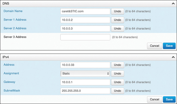
Figure 9-4 Network Setting Menus on a CE Software-Based Endpoint
Step 8. To configure the TFTP server address, choose the Provisioning menu in the left column.
Step 9. In the top section, ensure the Connectivity field is set to Auto, and then change the Mode to CUCM.
Step 10. Choose Save in the bottom-right corner of this section.
Step 11. In the ExternalManager section, enter the address of the TFTP server in the Address field. You can enter a second AlternateAddress as well, or just use a URL address for the Cisco TFTP Server cluster in the first Address field.
Step 12. Ensure the Protocol field is set to HTTP, and then choose the Save button in the bottom-right corner of that section.
Figure 9-5 illustrates how to configure the Provisioning settings on a CE software-based endpoint.
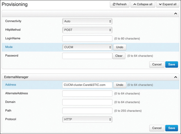
Figure 9-5 Configure Provisioning Settings on a CE Software-Based Endpoint
TFTP
IP phones and Telepresence endpoints rely on a TFTP-based process to acquire configuration files, software images, and other endpoint-specific information. The Cisco Unified Communications Manager runs a TFTP service as a file serving system, and this service can run on one or more Cisco Unified Communications Manager servers. It builds configuration files and serves firmware files, ringer files, device configuration files, and so forth, to endpoints. The TFTP file systems can hold several file types, such as the following:
Phone configuration files
Phone firmware files
Certificate trust list (CTL) files
Identity trust list (ITL) files
Tone localization files
User interface (UI) localization and dictionary files
Ringer files
Softkey files
Dial plan files for SIP phones
The TFTP server manages and serves two types of files: those that are not modifiable, such as firmware files for phones, and those that can be modified, such as configuration files. A typical configuration file contains a prioritized list of Cisco Unified Communications Managers for a device, the TCP ports on which the device connects to those Cisco Unified Communications Managers, and an executable load identifier. Configuration files for selected devices contain locale information and URLs for the messages, directories, services, and information buttons on the phone. When a device’s configuration changes, the TFTP server rebuilds the configuration files by pulling the relevant information from the Cisco Unified Communications Manager database. The new file is then downloaded to the phone after the phone has been reset. An example of a file being downloaded to a phone again could be if a single phone’s configuration file is modified, such as during Extension Mobility login or logout. Only that file is rebuilt and downloaded to the phone. However, if the configuration details of a device pool are changed, such as if the primary Cisco Unified Communications Manager server is changed, all devices in that device pool need to have their configuration files rebuilt and downloaded. For device pools that contain large numbers of devices, this file rebuilding process can impact server performance.
The TFTP server can also perform a local database read from the database on its co-resident subscriber server. A local database read not only provides benefits such as the preservation of user-facing features when the publisher is unavailable but also allows multiple TFTP servers to be distributed by means of clustering over the WAN. The same latency rules for clustering over the WAN apply to TFTP servers as apply to servers with registered phones. This configuration brings the TFTP service closer to the endpoints, thus reducing latency and ensuring failure isolation between the sites.
When a device requests a configuration file from the TFTP server, the TFTP server searches for the configuration file in its internal caches, the disk, and then remote Cisco TFTP servers, if specified. If the TFTP server finds the configuration file, it sends the file to the device. If the configuration file provides Cisco Unified Communications Manager names, the device resolves the names by using DNS and opens a connection to the Cisco Unified Communications Manager. If the device does not receive an IP address or name, it uses the TFTP server name or IP address to attempt a registration connection. If the TFTP server cannot find the configuration file, it sends a “file not found” message to the device.
A device that requests a configuration file while the TFTP server is processing the maximum number of requests will receive a message from the TFTP server that causes the device to request the configuration file later. The Maximum Serving Count service parameter, which is configurable, specifies the maximum number of requests that can be concurrently handled by the TFTP server. You can use the default value of 2500 requests if the TFTP service is run along with other Cisco CallManager services on the same server. For a dedicated TFTP server, you should use the following suggested values for the Maximum Serving Count: 2500 for a single-processor system or 3000 for a dual-processor system. The Cisco Unified IP Phones 7800 series and 8800 series request their TFTP configuration files over the HTTP protocol (port 6970), which is much faster than using the TFTP protocol.
Every time an endpoint reboots, an angel gets his wings. Not really; just wanted to make sure you’re still paying attention. Every time an endpoint reboots, the endpoint will send a TFTP GET message for a file whose name is based on the requesting endpoint’s MAC address. For a Cisco Unified IP Phone 8861 with a MAC address of abcdef123456, the filename would be SEPabcdef123456.cnf.xml. The received configuration file includes the version of software that the phone must run and a list of Cisco Unified Communications Manager servers with which the phone should register. The endpoint might also download ringer files, softkey templates, and other miscellaneous files to acquire the necessary configuration information before becoming operational. If the configuration file includes software file version numbers that are different from those the phone is currently using, the phone will also download the new software files from the TFTP server in order to upgrade the firmware on the phone or endpoint. The number of files an endpoint must download to upgrade its software varies based on the type of endpoint and the differences between the phone’s current software and the new software.
Option 150 allows up to two IP addresses to be returned to phones as part of the DHCP scope. The phone tries the first address in the list, and it tries the subsequent address only if it cannot establish communications with the first TFTP server. This address list provides a redundancy mechanism that enables phones to obtain TFTP services from another server even if their primary TFTP server has failed. Cisco recommends that you grant different ordered lists of TFTP servers to different subnets to allow for load balancing. An example of how this might look could be as follows:
In subnet 10.0.0.0/24: Option 150: TFTP1_Primary, TFTP1_Secondary
In subnet 10.1.1.0/24: Option 150: TFTP1_Secondary, TFTP1_Primary
Under normal operations, a phone in subnet 10.0.0.0/24 will request TFTP services from TFTP1_Primary, while a phone in subnet 10.1.2.0/24 will request TFTP services from TFTP1_Secondary. If TFTP1_Primary fails, phones from both subnets will request TFTP services from TFTP1_Secondary. Load balancing avoids having a single point of failure, where all phones from multiple clusters rely on the same server for TFTP service. TFTP load balancing is especially important when phone software loads are transferred, such as during a Cisco Unified Communications Manager upgrade, because more files of larger size are being transferred, thus imposing a bigger load on the TFTP server and on the network.
SIP Registration
As mentioned in Chapter 5, everything discussed up to this point in this chapter is not actually part of the SIP registration process; however, these processes had to transpire in order for SIP registration to the Cisco Unified Communications Manager to occur successfully. After the TFTP process has completed and the endpoint or phone has obtained all the system configuration information, SIP registration can occur. SIP endpoints must send a REGISTER request to a SIP server with a URI and a Call-ID, which is the IP of the endpoint registering. According to the IETF RFC 3621, a URI is made up of a host portion and a fully qualified domain name (FQDN) portion separated by an @ symbol, such as andy.dwyer@caret&stic.com. This is important to understand because the SIP registrar function of the SIP server breaks down these components individually to successfully process the REGISTER request. Each component is broken down as follows:
Request-URI: The Request-URI names the domain of the location service for which the registration is meant, such as sip:caret&stic.com. The userinfo and @ components of the SIP URI must not be present. The domain in the URI must be qualified by the SIP server for registration to occur.
To: The To header field contains the address of record whose registration is to be created, queried, or modified. The To header field and the Request-URI field typically differ because the former contains a username. This address of record must be a SIP URI or SIPS URI. Based on the preceding example, the request URI would be sip:andy.dwyer@caret&stic.com.
From: The From header field contains the address of record of the person responsible for the registration. The value is the same as the To header field unless the request is a third-party registration. Therefore, the From header will also be sip:andy.dwyer@caret&stic.com.
Call-ID: All registrations from a user agent client (UAC) should use the same Call-ID header field value for registrations sent to a particular registrar. If the same client were to use different Call-ID values, a registrar could not detect whether a delayed REGISTER request might have arrived out of order.
CSeq: The CSeq value guarantees proper ordering of REGISTER requests. A user agent (UA) must increment the CSeq value by one for each REGISTER request with the same Call-ID.
Contact: REGISTER requests may contain a Contact header field with zero or more values containing address bindings.
If you are already familiar with the Cisco Unified Communications Manager, you might see an issue here based on the IETF components needed for registering to the SIP registrar. The Cisco Unified Communications Manager uses directory numbers (DNs) for endpoint registration, not URIs. First, it’s important to understand that the IETF RFCs are just guidelines for how SIP should operate. They are not hard-set boundaries you have to follow. If you want to “color outside the lines with SIP, you can certainly do so. Second, a DN on the Cisco Unified Communications Manager is essentially a URI in its base form.
Suppose you have a phone you were trying to register to a Cisco Unified Communications Manager at 10.0.0.30 with the DN 2001. The “domain” would be the IP address of the Cisco Unified Communications Manager, so the DN would actually be [email protected]. If DNS were used in a Cisco Unified Communications Manager environment, and the URL for the Cisco Unified Communications Manager was cucm1.caret&stic.com, the DN would actually be 2001@caret&stic.com.
When calls are placed between the Cisco Unified Communications Manager and the Expressway Core, incoming requests will use this format and so must be changed accordingly. The Expressway will be discussed further in Part IV. What is different within a Cisco Unified Communications Manager environment is the dialing behavior on the back end. The Cisco Unified Communications Manager will treat DNs dialed differently than URIs dialed within the same cluster. Bringing the subject back to registration, even though DNs are technically used on the Cisco Unified Communications Manager, for the purpose of registration they are treated the same as any other URI. Consider how the Cisco Unified Communications Manager will separate the different components of a REGISTER request from an endpoint with the DN 2001:
Request URI: 10.0.0.30
To: sip:[email protected]
From: sip:[email protected]
CallID: [email protected]
CSeq: (101 REFER, 101 NOTIFY OR 101 SUBSCRIBE)
Contact: N/A
Verifying phone registration from the Cisco IP phone is quite simple. The easiest way to verify that a phone is registered is to look on the display screen. If you see a message across the top of the screen and a spooling circle, the phone is not registered. If you see the assigned phone DN, such as 2001, beside Line 1 and at the top of the screen, the phone is registered. You can verify other registration information by pressing the Settings button and then selecting the Phone Information menu. On this screen, you can see the following information:
Model Number, such as CP8845
IPv4 Address, such as 10.0.0.100
Host Name, which is the SEP<MAC Address>
Active Load, which is the Enterprise phone load version, such as sip8845_65.11-7-1-17
Last Upgrade, such as 07/04/2019 2:34pm
Active Server, such as ucm-sub1.caret&stic.com
Stand-by Server, such as ucm-pub.caret&stic.com
The last two options shown here signify that the phone is registered. These fields will be blank if the phone is not registered. Figure 9-6 illustrates an 8845 phone that has been registered to the Cisco Unified Communications Manager.

Figure 9-6 Home Screen of an 8845 Phone Registered to the CUCM
Verifying SIP registration on Cisco CE software-based endpoints is just as simple as verifying registration on Cisco IP phones. If you see a “Not Registered” message in the top-left corner of the screen, that is the indicator the phone is not registered. If you see the assigned phone DN, such as 2002, in the center of the screen or the Touch 10 controller, the phone is registered. You can verify other registration information by pressing the Settings button in the top-left corner of the screen and then selecting the System Information menu. On this screen, you can see the following information:
Video Address, such as 2002@caret&stic.com
IP Address, such as 10.0.0.101
MAC Address, such as AB:CD:EF:12:34:56
SIP Proxy, such as 10.0.0.30 (Registered)
Software, such as ce 9.1.5 d1c67fb 2017-11-16
Device, such as Cisco Telepresence DX80 TANDBERG
The SIP Proxy setting is another identifier that the endpoint is registered. For one thing, it says Registered. For another, this field will be blank or show Not Registered if there is an issue or if the phone has never been provisioned. Figure 9-7 illustrates a Cisco Telepresence DX80 that has been registered to the Cisco Unified Communications Manager.
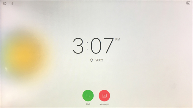
Figure 9-7 Home Screen of DX80 Endpoint Registered to the CUCM
ITL, CTL, and CAPF
Even though both an endpoint and the Cisco Unified Communications Manager might be located on the same LAN or WAN, it is still important to secure communications between these two products. Cisco offers several security measures, depending on what level of security you desire for the network you’re managing. The lowest level of security available on the Cisco Unified Communications Manager for endpoint registration is the identity trust list (ITL). A step above this option is the certificate trust list (CTL). The highest level of security available is the Certificate Authority Proxy Function, or CAPF. In order to better understand each of these types of security on the Cisco Unified Communications Manager, it is important to formulate a basic understanding of how secure communication over IP works in its base form. If security certificates is an unfamiliar topic to you, review the “Security” subsection under the “Designing a Cisco Collaboration Solution” section in Chapter 6.
Returning to the topic of securing communications between an endpoint or phone and the call control system, a Security By Default (SBD) mechanism called ITL and Trust Verification Service (TVS) is enabled on all Cisco Unified Communications Manager installments. IP phones contain a limited amount of memory, and there can also be a large number of phones to manage in a network. The Cisco Unified Communications Manager acts as a remote trust store via TVS so that a full certificate trust store does not have to be placed on each IP phone. Any time the phone cannot verify a signature or certificate via the CTL or ITL files, it asks the TVS server for verification. This central trust store is easier to manage than if the trust store were present on all IP phones. A number of files must be present on the Cisco Unified Communications Manager itself. The most important piece is the TFTP certificate and the TFTP private key. The TFTP certificate is located under OS Administration > Security > Certificate Management > CallManager.pem. The Cisco Unified Communications Manager uses the CallManager.pem certificate’s private and public keys for the TFTP service, as well as for the Cisco CallManager (CCM) service. All phones can use the TFTP public key in the CallManager.pem certificate to decrypt any file encrypted with the TFTP private key and to verify any file signed with the TFTP private key.
The presence of an ITL file will direct the phone to request a signed TFTP configuration file from the Cisco Unified Communications Manager TFTP server. The ITL file allows the phone to verify that the configuration file came from a trusted source. After the phone boots and obtains an IP address and the address of a TFTP server, it asks for the ITL files first. After the ITL file is downloaded, it must be verified. Several permutations could transpire here, including the following possibilities:
The phone has no ITL file present. In this state, the phone blindly trusts the next ITL file downloaded and uses this signature henceforth.
The phone already has an ITL file. In this state, the phone verifies that the recently downloaded files match the signature in either the ITL or TVS server.
After the signed configuration file is downloaded, the phone must authenticate it against the function for CCM+TFTP inside the ITL. After the phone receives the ITL files from TFTP successfully and they have been authenticated, the phone asks for a signed configuration file. This is the TFTP Get message discussed previously. With ITL files present on phones, configuration files must be signed by a trusted TFTP server. The file is plain text on the network while it is transmitted but comes with a special verification signature. The phone requests SEP<MAC Address>.cnf.xml.sgn to receive the configuration file with the special signature. This configuration file is signed by the TFTP private key that corresponds to CallManager.pem on the Operating System Administration Certificate Management page.
ITL is a leaner version of a CTL file. The CTL file contains a server certificate, public key, serial number, signature, issuer name, subject name, server function, DNS name, and IP address for each server. The CTL file can also contain entries for the following servers or security tokens:
System Administrator Security Token (SAST)
Cisco CallManager and Cisco TFTP services that are running on the same server
Certificate Authority Proxy Function (CAPF)
TFTP server(s)
ASA firewall
After you create the CTL file, you must restart the Cisco CallManager and Cisco TFTP services in Cisco Unified Serviceability on all nodes that run these services. The next time that the phone initializes, it will download the CTL file from the TFTP server. If the CTL file contains a TFTP server entry that has a self-signed certificate, the phone requests a signed configuration file in .sgn format. If no TFTP server contains a certificate, the phone requests an unsigned file. After the Cisco CTL client adds a server certificate to the CTL file, you can display the certificate in the CTL client GUI. When you configure a firewall in the CTL file, you can secure a Cisco ASA firewall as part of a secure Cisco Unified Communications Manager system. The Cisco CTL client displays the firewall certificate as a CCM certificate. Cisco Unified Communications Manager Administration uses an e-token to authenticate the TLS connection between the Cisco CTL client and Cisco CTL provider. The process of obtaining a CTL file is the same as with an ITL file, except that the CTL request must occur first. The CTL file is then used to verify the ITL when it is requested. If the phone already has a CTL but no ITL, the phone trusts an ITL only if it can be verified by the CCM+TFTP function in the CTL file.
The Certificate Authority Proxy Function, which automatically installs with the Cisco Unified Communications Manager, performs several tasks depending on your configuration. It can be used to authenticate via an existing manufacturing installed certificate (MIC), locally significant certificate (LSC), randomly generated authentication string, or optional less secure “null” authentication. It issues locally significant certificates to supported Cisco Unified IP phones. It upgrades existing locally significant certificates on the phones. CAPF also retrieves phone certificates for viewing and troubleshooting. During installation, a certificate that is specific for CAPF gets generated. This CAPF certificate, which the Cisco CTL client copies to all Cisco Unified Communications Manager servers in the cluster, uses the .0 extension.
When the phone interacts with CAPF, the phone authenticates itself to CAPF by using an authentication string, existing MIC or LSC, or “null”; generates its public key and private key pair; and then forwards its public key to the CAPF server in a signed message. The private key remains in the phone and never gets exposed externally. CAPF signs the phone certificate and then sends the certificate back to the phone in a signed message. Before you use CAPF, ensure that you have performed all necessary tasks to install and configure the Cisco CTL client. To use CAPF, you must activate the Cisco Certificate Authority Proxy Function service on the first node.
SIP Registration to Expressway Core
Up to this point, we’ve discussed the registration process to the Cisco Unified Communications Manager using both the Cisco Unified IP phones and the Cisco Telepresence endpoints. Throughout the rest of this chapter, the focus will be on the Cisco Telepresence endpoints because the Cisco Unified IP phones cannot register to the Cisco Expressway. A proxy registration function using Mobile and Remote Access (MRA) allows Cisco Unified IP phones to register to the Cisco Unified Communications Manager through the Expressway Core and Edge, but in this type of deployment, the registration is still to the Cisco Unified Communications Manager. This section of the chapter will focus on direct registration to the Cisco Expressway, which is intended for Cisco Telepresence endpoints and third-party endpoints.
Unlike the Cisco Unified Communications Manager, the Cisco Expressway does not have an easy provisioning mode available natively through which endpoints can register. There is a way to provision registration to a Cisco Expressway through another application called the Cisco Telepresence Management Suite (TMS), but TMS will not be discussed in this book. Therefore, endpoints that will register to the Cisco Expressway must be manually configured before they can register. This is one of the reasons the Cisco Unified Communications Manager is a preferred call control system. However, some circumstances require endpoints to register to the Expressway. A company may be using legacy Tandberg endpoints or third-party endpoints that cannot register to the Cisco Unified Communications Manager. Another reason could be that a company is already using a legacy VCS call control system and wants to upgrade to Expressway and continue to use the same system. Whatever the reason, this section will describe how to register SIP endpoints to the Cisco Expressway.
DHCP versus Static IP
Chapter 5 discussed the registration process to an Expressway using SIP. The following is a summation of that process for a quick review:
An endpoint obtains local power from the power cube and loads the locally stored image file. The exception is the SX10, which could obtain power from a power cube or PoE.
Cisco CE software-based endpoints can use CDP for VLAN discovery, but VLAN discovery will not impact Expressway-C registration.
When VLAN discovery is complete, or if the endpoint does not discover the VLAN, the endpoint will send a DHCP discovery message to the DHCP server. Alternatively, the endpoint may be configured with static network settings.
The SIP URI and Expressway IP address are configured manually on the endpoints.
The final step in the process is for the endpoints to register to the Cisco Expressway. The endpoints will send an IP address and alias to the Cisco Expressway in the REGISTER request. The alias must be in the form of a URI (name@FQDN), and the domain of the alias must match one of the domains configured in the Domain database of the Expressway.
If there are no configured restrictions on the Expressway, it will respond with the SIP message “200 OK.” The registration process is now complete.
The SIP registration process to the Cisco Expressway is much easier to explain because there are not as many moving parts. As is evident in the preceding steps, no PoE settings need to be configured because most of the endpoints do not support PoE. No VLAN settings have to be configured because the default VLAN can be used to register to the Cisco Expressway. The Expressway will tag voice and video packets, so the voice VLAN can be used but is not required for QoS purposes. This brings the process to the network addressing step. DHCP can be used on Telepresence endpoints, but it is recommended to use static IP addressing for several reasons. First, there is always the possibility that the IP address can change when DHCP is being used. This can negatively impact several aspects of Telepresence endpoint registration. The Expressway identifies endpoints registered by the IP address, not the MAC address, as does the Cisco Unified Communications Manager. Therefore, if the IP address changes, there could be duplicate registration entries for a single endpoint on the Cisco Expressway, causing call-routing issues. The IP address changing will also prevent, or at least slow down, an administrator from accessing the Telepresence endpoint remotely, which brings up the second reason static addresses should be used. The Cisco Telepresence endpoints support a high-functioning web interface and a command-line interface that can be accessed via the IP address. Cisco Unified IP phones do not have as robust of an interface; therefore, administrators do not need constant access to those addresses. All of the features a unified IP phone can support are managed through the Cisco Unified Communications Manager. A Cisco Telepresence endpoint, on the other hand, has many features supported directly on the endpoint itself, and accessing many of those features requires an IP address to access the Web interface of the endpoint, or access it through the CLI. Another reason static IP addressing is recommended on Cisco Telepresence endpoints is the newer API integrations that can be configured on newer versions of the CE software-based endpoints. There may be many more reasons why static addressing should be used over DHCP, but at the end of the day, you should use whatever method works best for your environment. Both methods will work in the end.
If you choose to use static IP addressing, the following instructions will provide some direction to change the default DHCP value to Static and configure all the necessary settings to render the Cisco Telepresence endpoint functional. Note that changing the IP address on a Cisco Telepresence endpoint will not impact access until after the system has been rebooted. A binding process must take place between the new IP address and the endpoint while the old address is purged from the system, which can occur only during a reboot. Therefore, you can make all the necessary changes over the web interface or CLI without losing the connection to the endpoint. However, after the reboot process has started, you will need to use the “new” IP address to regain access to the system. This first set of instructions will guide you through changing the IP settings using the web interface. This process is similar to the previously described process under the “DHCP” section.
Step 1. Log in to the web interface for the CE endpoint you want to configure.
Step 2. Navigate to Setup > Configuration > Network and locate the DNS section (second section down from the top).
DNS settings are not required for SIP registration to the Cisco Expressway. There may be reasons you may or may not want to configure these settings, so they are included for you to decide whether to use them.
Step 1. Enter the Domain in the Domain Name field. Enter up to three DNS addresses in the Server 1 Address, Server 2 Address, and Server 3 Address fields.
Step 2. Choose Save in the bottom-right corner of this section, and then scroll down to the IPv4 section.
Step 3. Change the Assignment field from DHCP to Static.
Step 4. Enter an IP address for the endpoint in the Address field. Enter the Default Router address in the Gateway field, and enter the Subnet Mask address in the SubnetMask field. All three of these fields are required for proper routing across the network.
Step 5. Choose Save in the bottom-right corner of this section.
Step 6. You will have to restart the endpoint before these changes will take effect. To restart the endpoint, choose Maintenance > Restart. Click the blue Restart Device button. When a popup window appears, click the red Restart button, and the system will go through a restart process. This will take about 60 seconds to complete.
One of the nice aspects to the design of the Cisco Telepresence CE software-based endpoints is the continuity between the web interface menu structure and the CLI command structure. To access the configuration menus from the web interface, you were instructed previously to choose Setup > Configuration. To access the configuration menus from the CLI, you need to enter the command xConfiguration. By the way, you can use abbreviations, such as xconfig, and you can use the Tab key to finish commands. Also, if you are not sure of what the next command should be, use the question mark and press Enter. A list of possible commands will be displayed. The next menu on the web interface to select is the Network menu from the left column. In the CLI, the next word to enter after xConfiguration is Network. On the web interface, if you wanted to configure the domain name, you would scroll down to the DNS section and find the Domain Name field. From the CLI, if you wanted to configure the domain name, you would enter the command xConfiguration Network 1 DNS Domain Name: followed by the domain name you want to configure. Figure 9-8 illustrates the continuity of these two interfaces with a side-by-side comparison between the CLI and the web interface configuration options for the network settings.
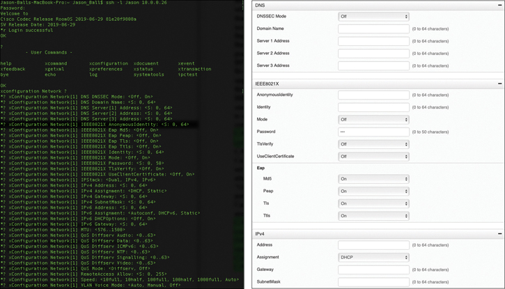
Figure 9-8 CLI and Web Interface Comparison for Network Configuration
To access the CLI of a CE software-based endpoint, you can open the terminal emulator of your choosing. PuTTY is a popular tool to use from Windows-based computers, and it is free to download. The preceding example is taken from Terminal, which comes with Apple Mac computers. You also can use other emulator tools, so do your homework if you do not already have a preference. Some will be free, and others you will have to pay for. You will need to use SSH to access the endpoint’s CLI. Telnet is supported, but it is disabled by default. For security reasons, it is recommended to leave Telnet disabled. From PuTTY, open the emulator and enter the IP address in the Host Name (or IP address) field. Choose the SSH radio button below that field, and then click the Open button. From Terminal, enter the command ssh -l admin IP address and then press Enter. Both tools will prompt you to validate the certificate and then prompt you to log in. With Terminal, the username is already added to the access command, so you will only need to enter the password. With PuTTY, you will need to enter the username first followed by the password. After you are logged in, you can enter the commands to configure the endpoint. The following is a list of network commands that can be entered through the CLI. Use the up-arrow key to recall the last command entered. Commands in the CLI are not case sensitive.
xConfiguration Network 1 DNS Domain Name: domain
xConfiguration Network 1 DNS Server [1-3] address: IP of DNS
xConfiguration Network 1 IPv4 Assignment: [DHCP | Static]
xConfiguration Network 1 IPv4 Address: IP address for endpoint
xConfiguration Network 1 IPv4 Gateway: default gateway IP address
xConfiguration Network 1 IPv4 SubnetMask: subnet mask IP address
xCommand Boot
Because the last command does not configure any settings on the endpoint, it does not use the xConfiguration level of command. xCommand is the structure level that tells the system to execute a function. In this case, the endpoint must go through a reboot process to bind the IP address with the endpoint. After the reboot process begins, the connection to the emulator will terminate. You will need to use the new IP address to access the system remotely again.
Manual Configuration of SIP Settings
After the network settings have been configured on the CE software-based endpoint, you can configure the SIP settings so that the endpoint can try registering to the Cisco Expressway. When a CE software-based endpoint is first booted, a setup wizard runs on the endpoint. You can choose whether the endpoint will register to Cisco Webex or to Other Services. After you select Other Services, the options presented are Cisco UCM, Cisco UCM via Expressway, VCS (VCS can also be an Expressway Core), or Advanced Setup. When you select the Cisco UCM option, a field called Enter Server Address will populate so that you can configure the TFTP server address. When you select the Cisco UCM via Expressway option, three fields will be populated: Username, Passphrase, and Domain. When you select the VCS option, four fields will be populated: Host Server Address, Username, Passphrase, and Domain. When you select the Advanced Setup option, the next screen will provide a warning: “Advanced setup is an option for administrators to directly set up the system with their own software. If you continue you will not be able to call until you register with a service.” The steps outlined here assume Advanced Setup is the option you chose on the endpoint. Two methods can be used to manually configure a CE software-based endpoint to an Expressway Core. The administrator can use the web interface or the CLI, as mentioned previously with the network settings options. This section will first examine the web interface options for configuring the SIP registration settings on a CE endpoint.
First, you need to obtain the IP address from the endpoint and enter this address in the address bar on a web browser. You can use either HTTP or HTTPS to access the endpoint by default, although you may want to disable HTTP for security reasons. When the login screen appears, enter the Username admin and leave the Passphrase field bank. CE software-based endpoints do not have a password set on them by default. The administrator will need to set this password. If you want to go ahead and set a password on the endpoint, click the Admin link in the top-right corner of the screen and select the Change Passphrase menu option. You can also navigate to Security > Users and select the Admin user account to gain access to this screen. You will be prompted to enter the Current Passphrase, Passphrase, and Repeat Passphrase. Here, leave the first field blank, enter a password in the second and third fields, and then click the Change Passphrase button. Now you are ready to configure the SIP registration settings to the Expressway Control. Navigate to Setup > Configuration and follow these steps:
Step 1. Choose NetworkServices from the menu column on the left of the screen, and ensure the SIP Mode setting is set to On. This is the default setting.
Step 2. Choose Provisioning from the menu on the left and change the Mode to VCS. This is an optional step because registration to the Expressway Core will occur whether this setting is changed or not. The mode could also be set to TMS or Auto and still register to the Expressway Core. Click Save after changing the setting.
Step 3. Choose SIP from the menu column on the left. You can configure several settings under this menu. Some of those settings are as follows:
DefaultTransport: This setting defines the default mechanism used when SIP communications are sent. The values can be set to Auto, TCP, TLS, or UDP. The default value is Auto. You can leave this setting as Auto or change it to another value. For security reasons, you may want to change this setting to TLS.
DisplayName: This is an optional setting. If the display name is set, when a call is placed from or to this endpoint, this name will be displayed to the participants on the other end of the call. If this value is not configured, the URI address will be displayed as the name.
Proxy 1 Address: This is a required field to be configured. This is where you will need to enter the address of the Expressway Core. If DNS is configured on this endpoint, you can enter the URL of the Expressway Core. If DNS is not being used, you will need to enter the IP address of the Expressway Core. In either case, some setting must be configured in this field.
TLS Verify: This setting should be enabled only if TLS Verified is being used. You will first need to upload a signed certificate to this endpoint, DNS will have to be enabled, and the Proxy 1 Address will have to be a URI. The default value for this setting is Off.
Type: Two types of SIPs can be used on CE software-based endpoints. Standard is the default value, and the value that should be selected when registering to the Expressway Core. Cisco is the other value option and should be used only when registering to the Cisco Unified Communications Manager. When the Provisioning > Mode is set to CUCM, this value will change automatically to Cisco.
URI: This is the URI address assigned to this endpoint. This is a required field because the Expressway Core will check the domain portion of the URI address against a domain database within the Expressway before allowing registration. The URI should be in the form of Host@FQDN.
Step 4. After you configure all the settings under this section, click the Save button.
Registration should occur instantaneously. To verify the endpoint has registered successfully, choose Home from the menus at the top of the screen. On the right side of the screen under the SIP Proxy 1 heading, you should see the registration status of the endpoint. Figure 9-9 illustrates the SIP Configuration menus on a DX80 endpoint.

Figure 9-9 SIP Configuration Menus on DX80 Endpoint
Another method that you can use to manually configure a CE software-based endpoint to register with an Expressway Core is to use the CLI. The preceding section discussed different terminal emulators that can be used for CLI access and explained the process to log in to the endpoint using the PuTTY and Terminal emulators. The following CLI commands can be used to configure all of the settings previously mentioned using the web interface:
xConfiguration NetworkServices SIP Mode: On
xConfiguration Provisioning Mode: VCS
xConfiguration SIP DefaultTransport: tls
xConfiguration SIP DisplayName: Andy_Dwyer_DX80
xConfiguration SIP Proxy 1 Address: exp-c.caret&stic.com
xConfiguration SIP URI: andy.dwyer@caret&stic.com
xStatus SIP
All of the settings in italic in the preceding list are examples of the values that you can add. Obviously, you would want to configure your own unique values in each of these fields. The last command, xStatus SIP, is how you can check the registration status for SIP on the endpoint. This will display all the settings configured for SIP with their values, the Registration 1 Status, and the Registration 1 URI address.
H.323 Registration to the Expressway Core
In addition to supporting SIP registration, the Cisco Expressway can also support H.323 registration. As discussed in Chapter 5, H.323 is an ITU-T standard for packet-switched communication over IP. H.323 and SIP cannot communicate with one another unless there is a gateway to bridge the differences between the two communication protocols. Therefore, the Expressway has a built-in SIP to the H.323 gateway that is enabled by default. This gateway can also bridge communications between IPv4 and IPv6. When communicating between SIP and H.323, it is important to pay attention to the aliases being used because the different alias mechanisms between the two protocols can cause further complications in bridging the communication chasm. Other tools within the Expressway can aid in bridging this gap, but they will not be discussed in this book.
H.323 Aliases
An alias can be generally defined as any identification method that is not an IP address. When video endpoints in a network are known to the rest of the environment only by their IP addresses, many limitations can occur. These limitations can be summarized by saying that having some flexibility and customization available to the administrator serves everyone well in terms of overall system administration, security, dial plan effectiveness, and so on. The two primary conferencing protocols, SIP and H.323, use very different alias methodologies and when not implemented properly can create unnecessary workload or configuration challenges.
H.323 aliases can take three forms. First, H.323ID is an alphanumeric string of characters that includes special characters but no spaces, such as room231 or helpdesk. The H.323ID can also be configured in the form of a URI, such as andy.dwyer@caret&stic.com. Make no mistake: this is an H.323 ID and not a URI. Remember that the FQDN in the URI for SIP must be qualified against a domain configured in the Expressway. However, with an H.323 ID, the supposed “domain” part of the alias is not qualified against anything. The second alias supported with H.323 is an E.164 alias. This type of alias can only be configured with numeric values consisting of 1–15 digits. Incidentally, the E.164 protocol is a holdover from PSTN protocols and serves to unify legacy ISDN endpoints with newer IP-based endpoints. The third type of alias is a routing prefix. These prefixes are registered aliases that have been configured on gateways and bridges. They serve to route all calls that were dialed with that prefix number to the server that registered the routing prefix. For example, if an ISDN gateway were to register with a routing prefix of 9, and a user dialed 919195551001, the Expressway would identify the first digit as a routing prefix, ignore all the numbers that followed, and route the call to the ISDN gateway. The call connection would then depend on the routing rules configured in the ISDN gateway to match the call attempt and connect it across the PSTN to the number dialed. Another example could be an MCU of some type that registered a routing prefix of 814. When a user dialed 8144001, the Expressway would match the 814 prefix and route the call to the MCU regardless of remaining digits dialed. This second example serves to illustrate that a prefix does not have to be a single digit. It could contain multiple digits, but it should be kept simple so that dialing among employees does not become a cumbersome task. Endpoints do not use prefixes, so this alias type would not apply to them.
The previous information that a single endpoint can have as many as two different aliases is significant because the Expressway identifies endpoints by their alias. The Expressway will, therefore, make all its security, access, and bandwidth management decisions based on the alias of an endpoint, and will only be concerned with IP addresses when regarding routing the signaling and media. When an administrator is planning and configuring the dial plan for Cisco Expressway call routing, how the Expressway will treat each alias must be given careful consideration.
Manual Configuration of H.323 Settings
Just as with SIP registration configurations on CE software-based endpoints, H.323 registration configurations can be made using the web interface or the CLI. The following steps outline how to configure H.323 settings on CE software-based endpoints for registration to the Gatekeeper function on the Cisco Expressway Core. H.323 and SIP cannot be used simultaneously on CE software-based endpoints. Therefore, SIP will need to be disabled when H.323 is enabled on the endpoint.
Step 1. Log in to the web interface for the CE endpoint you want to configure.
Step 2. Choose Setup > Configuration.
Step 3. Choose NetworkServices from the menu column on the left side of the screen.
Step 4. Change the SIP Mode setting to Off, and then change the H.323 Mode to On. This setting is Off by default. Click Save when finished.
Step 5. Choose Provisioning from the menu on the left and change the Mode to VCS. This is an optional step because registration to the Expressway Core will occur whether this setting is changed or not. The mode could also be set to TMS or Auto and still register to the Expressway Core. Click Save after changing the setting.
Step 6. Choose H323 from the menu on the left. Several settings under this menu can be configured. Some of those settings are as follows:
CallSetup Mode: This setting can be set to Gatekeeper, which is the default, or Direct. If Gatekeeper is chosen, the endpoint must register to an H.323 Gatekeeper before it can place and receive calls. If the endpoint is set to Direct, it will never try to register but can place calls based on IP address dialing.
Gatekeeper Address: This is where the IP address or URL of the Cisco Expressway Core needs to be entered for the endpoint to register.
Authentication: Three settings pertain to authentication for H.323 registration:
LoginName: This is the login name used when Authentication services are enabled on the Expressway Core. If Authentication services are not enabled on the Expressway Core, this field can be left blank.
Mode: This setting can be set to On or Off (default is Off). Authentication mode does not need to be turned on unless Authentication services are enabled on the Expressway Core. If this mode is turned on and Authentication services are not enabled on the Expressway Core, it will not impact registration. This setting will just be ignored by the Expressway Core.
Password: This setting coincides with the Authentication username when the Authentication services are enabled on the Expressway Core.
H323Aliases: Two aliases can be configured on CE software-based endpoints.
E164: This is the numeric alias assigned to H.323 endpoints. Digits can range between 0 and 9, and aliases can be composed of up to 15 digits in length.
ID: This alias can contain alphanumeric and special characters up to 32 characters in length.
There are several more settings than what has been listed here, but the remainder of the settings are seldom used and therefore do not warrant any discussion. Figure 9-10 illustrates the previously described settings for H.323 configuration under the H.323 menu on a Cisco DX80 endpoint.
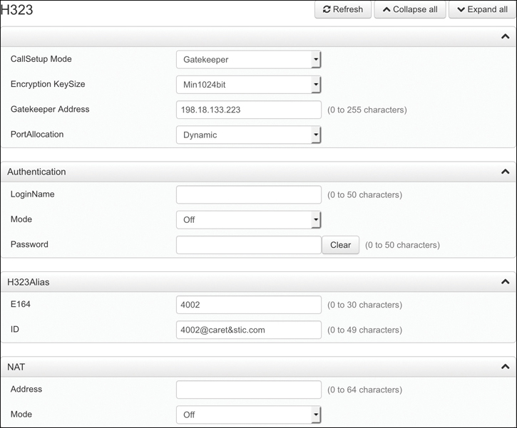
Figure 9-10 H.323 Registration Menus on Cisco DX80
Another method that you can use to manually configure a CE software-based endpoint to register with an Expressway Core is to use the CLI. The CLI commands that can be used to configure all of the H.323 settings previously mentioned using the web interface are as follows:
xConfiguration NetworkServices SIP Mode: Off
xConfiguration NetworkServices H323 Mode: On
xConfiguration Provisioning Mode: VCS
xConfiguration H323 CallSetup Mode: Gatekeepr
xConfiguration H323 Gatekeeper Address: exp-c.caret&stic.com
xConfiguration H323 Authentication LoginName: “”
xConfiguration H323 Authentication Mode: Off
xConfiguration H323 Authentication Password: “”
xConfiguration H323 H323Alias E164: 4002
xConfiguration H323 H323Alias ID: 4002@caret&stic.com
xStatus H323
All of the settings in italic in the preceding list are examples of the values that you can add. Obviously, you would want to configure your own unique values in each of these fields. Because the Authentication Username and Password are not needed in this example, quotation marks are used to show there is no value in that field. Quotation marks can be used to remove a setting as well. The last command, xStatus H323, is how you can check the registration status for H.323 on the endpoint. This will display the H.323 Gatekeeper Address, Port, Mode as Enabled, and Status as Registered. Aliases will not be displayed with the xStatus H323 command. To see the alias configured on this system, type xConfiguration H323 and press Enter. All H.323 settings will be displayed as they have been configured.
Exam Preparation Tasks
As mentioned in the section “How to Use This Book” in the Introduction, you have a couple of choices for exam preparation: the exercises here, Chapter 32, “Final Preparation,” and the exam simulation questions in the Pearson Test Prep Software Online.
Review All Key Topics
Review the most important topics in this chapter, noted with the Key Topics icon in the outer margin of the page. Table 9-4 lists a reference of these key topics and the page numbers on which each is found.
Table 9-4 Key Topics for Chapter 9
Key Topic Element |
Description |
Page Number |
|---|---|---|
Meraki Switch PoE Classifications |
197 |
|
Three PoE Types Supported on Cisco Switches |
198 |
|
Commands |
Enabling PoE on a Cisco Switch Port |
198 |
Commands |
Enabling CoS on Cisco Switches |
201 |
Paragraph |
Dual VLAN Tagging on a Switchport |
203 |
List |
Configure VLANs on Cisco 8800 Series Phones |
203 |
List |
Configure VLANs on Cisco CE Software-Based Endpoints |
204 |
Commands |
Configure DHCP with Option 150 on Cisco Router |
205 |
List |
DHCP Settings on Cisco 8800 Series Phones |
207 |
List |
DHCP Settings on Cisco CE Software-Based Endpoints |
208 |
List |
TFTP System File Types |
209 |
Paragraph |
TFTP GET Process Between Phone and CUCM |
210 |
List |
Components of a SIP REGISTER Request |
211 |
Paragraph |
TVS Explained |
215 |
Paragraph |
CAPF Explained |
216 |
Paragraph |
Static IP versus DHCP on Telepresence Endpoints |
217 |
List |
CLI Commands on CE Endpoints to Configure Network Settings |
220 |
List |
Steps to Configure SIP Registration to an Expressway via Web Interface |
221 |
Paragraph |
Three Forms of H.323 Aliases |
223 |
List |
Steps to Configure H.323 Registration to an Expressway via Web Interface |
224 |
Define Key Terms
Define the following key terms from this chapter and check your answers in the glossary:
Command Reference to Check Your Memory
This section includes the most important configuration and EXEC commands covered in this chapter. It might not be necessary to memorize the complete syntax of every command, but you should be able to remember the basic keywords that are needed.
To test your memory of the commands, cover the right side of Table 9-5 with a piece of paper, read the description on the left side, and then see how much of the command you can remember.
Table 9-5 Cisco Meeting Server MMP Commands
Task |
Command Syntax |
|---|---|
This command enters configuration mode. |
Switch# Configure Terminal |
This command selects the interface to configure. |
Switch(config)# interface {fastethernet | gigabitethernet} (slot/port) |
The auto keyword sets the interface to automatically detect and supply power to the powered device. This is the default configuration. The static keyword sets the interface to higher priority than auto. If necessary, you can use the max keyword to specify the maximum wattage allowed on the interface (4000 to 15,400 milliwatts). You can use the never keyword to disable detection and power for the PoE-capable interface. |
Switch(config-if)# power inline {auto[max milli-watts] | never | static [max milli-watts]} |
This command exits configuration mode. |
Switch(config-if)# end |
This command displays the PoE state for the switch. |
Switch# show power inline {fastethernet | gigabitethernet} slot/port |
This command configures the port to delay shutting down. |
Switch(config-if)# power inline delay shutdown 20 initial 300 |
This command creates a VLAN and associated number value. |
Switch(config)# vlan number |
This command provides a description of the VLAN. |
Switch(config-vlan)# name name |
This command enables the switchport to trust the CoS-to-QoS mapping embedded in the switch. |
Switch(config-if)# mls qos trust cos |
The detect command configures the interface to detect and recognize a Cisco IP phone. The cisco-phone option is the only one allowed when you initially implement the switchport voice detect command. The default is no switchport voice detect cisco-phone [full-duplex]. The optional full-duplex command configures the switch to accept only a full-duplex Cisco IP phone. The vlan-id command configures the phone to forward all voice traffic through the specified VLAN. By default, the Cisco IP phone forwards the voice traffic with an IEEE 802.1Q priority of 5. Valid VLAN IDs are 1 to 4094. The dot1p command configures the phone to use IEEE 802.1p priority tagging for voice traffic and to use the default native VLAN (VLAN 0) to carry all traffic. The none command allows the phone to use its own configuration to send untagged voice traffic. The untagged command configures the phone to send untagged voice traffic. |
Switch(config-if)# switchport voice {detect cisco-phone [full-duplex] | vlan {vlan-id | dot1p | none | untagged}} |
This command is used to hard-code the port into access mode. |
SW1(config-if)# switchport mode access |
This command is used for access VLAN tagging all data originating from the computer. |
SW1(config-if)# switchport access vlan number |
This command is used for voice VLAN tagging all voice and video traffic originating from the phone. |
SW1(config-if)# switchport voice vlan number |
This command creates a pool from which IP addresses can be issued to devices that send a DHCP request. The name field can be any name you want to give to the pool. |
Router(config)# ip dhcp pool name |
This command establishes all the available addresses within a pool that can be used for DHCP assignment. |
Router(dhcp-config)# network starting IP address subnet mask |
This command establishes the default gateway address that will be assigned to devices. |
Router(dhcp-config)# default-router default gateway address |
This command assigns the TFTP server address to the endpoint. You could also use the option 66 ip address command here, but Cisco recommends using Option 150 to add additional redundancy. |
Router(dhcp-config)# option 150 TFTP server address |
This command allows you to list up to four DNS server addresses. You must separate DNS addresses with a space. |
Router(dhcp-config)# dns-server DNS address |
This command enables you to assign the domain to devices through DHCP. |
Router(dhcp-config)# domain-name name |
This command determines how long a leased address can be used by a device before a new lease has to be requested. By default, the duration of a lease is one day. When you enter the lease n command, this duration will be extended to that number n of days. You can enter three values here to extend the duration to days, hours, and minutes. |
Router(dhcp-config)# lease n |
This command issues an exclusion range of addresses that will not be used in DHCP assignments. |
Router(config)# ip dhcp excluded-address starting IP address ending IP address |
The CLCOR (350-801) exam focuses on practical, hands-on skills that are used by a networking professional. Therefore, you should be able to identify the commands needed to configure and test switch commands for PoE and QoS, and router commands for DHCP and Option150.
Q&A
The answers to these questions appear in Appendix A. For more practice with exam format questions, use the Pearson Test Prep Software Online.
1. List the three PoE protocols supported on Cisco switches and the maximum watts each can support.
2. Assuming the data VLAN ID is 100 and the VVID is 200, list the commands required to apply both the voice and data VLANs to a switchport.
3. What are the two options that can be configured in a DHCP server so that the TFTP server address can be discovered by an endpoint?
4. List the nine different file types that the TFTP file system can hold.
5. List the six different fields found in a SIP REGISTER header.