
Chapter 15
Cisco Unified Communications Manager Setup
This chapter covers the following topics:
Services: This topic will introduce the two different types of services that exist on the Cisco Unified Communications Manager and explain how to enable services needed for basic Cisco Unified Communications Manager operation.
Enterprise Parameters: This topic will introduce the enterprise parameters that exist for all nodes within a Cisco Unified Communications Manager cluster.
Service Parameters: This topic will examine how to configure service parameters for feature services that have been enabled on the Cisco Unified Communications Manager.
Other Settings: This topic will overview other key settings that may need to be configured on the Cisco Unified Communications Manager for production use.
Codec Negotiations using Regions: This topic will bring the audio and video basics discussed in Part 1 to an applicable configuration within the Cisco Unified Communications Manager as regions are used to apply audio and video codecs to groups of endpoints.
The Cisco Unified Communications Manager has been described in the past as a very complex solution that is difficult to understand and configure. However, this highly complex solution also offers incredible granularity in how it can manage a collaboration solution. This chapter begins an intricate examination of how to set up and utilize the many tools available through the Cisco Unified Communications Manager. Before an organization can begin using this system, some foundational settings must be configured. This chapter will explain these foundational settings and how to configure them. Topics discussed in this chapter include the following:
Services
Enterprise Parameters
Service Parameters
Other Settings
Groups
Device Settings (Device Defaults, Phone Button Template, Soft Key Template)
Phone Services
SIP Profile
Device Pool Settings
Codec Negotiations Using Regions
This chapter covers the following objectives from the Cisco Collaboration Core Technologies v1.0 (CLCOR 350-801) exam:
2.2 Identify the appropriate collaboration codecs for a given scenario
2.3 Configure codec negotiations
3.1 Configure these voice gateway elements
3.1.a DTMF
3.5 Identify the appropriate media resources for a given scenario (hardware and software)
“Do I Know This Already?” Quiz
The “Do I Know This Already?” quiz allows you to assess whether you should read this entire chapter thoroughly or jump to the “Exam Preparation Tasks” section. If you are in doubt about your answers to these questions or your own assessment of your knowledge of the topics, read the entire chapter. Table 15-1 lists the major headings in this chapter and their corresponding “Do I Know This Already?” quiz questions. You can find the answers in Appendix A, “Answers to the ‘Do I Know This Already?’ Quizzes.”
Table 15-1 “Do I Know This Already?” Section-to-Question Mapping
Foundation Topics Section |
Questions |
|---|---|
Services |
1–2 |
Enterprise Parameters |
3 |
Service Parameters |
4 |
Other Settings |
5–8 |
Codec Negotiations Using Regions |
9–10 |
Caution
The goal of self-assessment is to gauge your mastery of the topics in this chapter. If you do not know the answer to a question or are only partially sure of the answer, you should mark that question as wrong for purposes of the self-assessment. Giving yourself credit for an answer you correctly guess skews your self-assessment results and might provide you with a false sense of security.
1. Which of the following is only a network service category on the CUCM?
CDR Services
CM Services
Performance and Monitoring Services
SOAP Services
2. At a minimum, which two of the following feature services must be enabled? (Choose two.)
Cisco CallManager
Cisco CTIManager
Cisco TFTP
Cisco DirSync
Cisco Device Activation Service
Cisco AXL Web Service
3. Which of the following statements about enterprise parameters is true?
Enterprise parameters must be configured on each peer within a CUCM cluster.
Enterprise parameters are applied clusterwide across all CUCM peers within the cluster.
Dependency records are enabled by default and must be disabled in the enterprise parameters if an administrator does not want to use them.
URL parameters default using the CUCM’s IP address and must be changed to use the URL if DNS reliance is desired.
4. What is the purpose of the T302 timer?
T302 timers are the bases for call reporting, accounting, and billing.
It lists various codecs of voice media-streaming applications.
It specifies the interdigit timer for variable-length numbers.
It sets the NTP reference and time zone for phones.
5. What is the maximum number of Server nodes in a CUCM cluster that can run the CallManager service?
2
4
8
12
6. Which of the following is a disadvantage to using a 1:1 redundancy group on the CUCM?
Upgrading servers may cause temporary outages.
If multiple primary servers fail, the backup servers may be overwhelmed.
1:1 redundancy groups are more complex to deploy.
The cost of deploying 1:1 redundancy groups is higher than other options.
7. Where would an administrator customize the phone button templates for phones registering to the CUCM?
Device > Phone
Device > Device Settings
System > Device Pool
User Management > End User
8. Where would an administrator configure a Media Resource Group List for all phones in a particular location to use?
Device > Phone
Device > Device Settings
System > Device Pool
User Management > End User
9. How much bandwidth is required for a video call using the H.263 codec at 1080p30 resolution?
768 kbps
1024 kbps
1536 kbps
2048 kbps
10. Which of the following is an important region setting for audio that should be selected along with the codec selection?
Compression setting
Bandwidth rate
Video codec
Video bandwidth rate
Foundation Topics
Services
A service on the Cisco Unified Communications Manager is a set of parameters that encapsulate a specific feature or function within the Cisco Unified Communications Manager. When a cluster is set up, each server in a Cisco Unified Communications Manager cluster can fulfill different tasks, such as running a TFTP or DHCP server, being the database publisher, processing calls, or providing media resources. Depending on the usage of a server, different services must be activated on the system. There are two types of services on Cisco Unified Communications Manager servers: network services and feature services.
Network services are automatically activated on each Cisco Unified Communications Manager node and are required for the operation of the server. Network services cannot be activated or deactivated by the administrator, but they can be stopped, started, or restarted. To perform these actions on network services, the administrator should select Cisco Unified Serviceability from the Navigator drop-down menu in the top-right corner of the screen and then choose Tools > Control Center–Network Services. Then you can select a server from the drop-down list to view the network services for that server. Figure 15-1 illustrates the Network Services menu and options on the Cisco Unified Communications Manager.

Figure 15-1 Network Services on the CUCM
The network services by category are as follows:
Performance and Monitoring: Cisco CallManager Serviceability RTMT, Cisco RTMT Reporter Servlet, Cisco Log Partition Monitoring Tool, Cisco Tomcat Stats Servlet, Cisco RIS Data Collector, Cisco AMC Service, Cisco Audit Event Service
Platform Services: Platform Administrative Web Service, A Cisco DB, A Cisco DB Replicator, SNMP Master Agent, MIB2 Agent, Host Resources Agent, Cisco CDP Agent, Cisco Syslog Agent, Cisco Certificate Expiry Monitor, Cisco Certificate Change Notification, Cisco Tomcat, Platform Communication Web Service, Cisco Smart License Manager
System Services: Cisco CallManager Serviceability, Cisco CDP, Cisco Trace Collection Servlet, Cisco Trace Collection Service
DB Services: Cisco Database Layer Monitor
Admin Services: Cisco CallManager Admin
SOAP Services: SOAP-Real-Time Service APIs, SOAP-Performance Monitoring APIs, SOAP-Log Collections APIs, SOAP-Diagnostic Portal Database Service
Backup and Restore Services: Cisco DRF Local, Cisco DRF Master
CDR Services: Cisco CDR Repository Manager, Cisco CDR Agent, Cisco CAR Scheduler, Cisco SOAP-CallRecord Service, Cisco CAR DB
CM Services: Cisco Extension Mobility Application, Cisco User Data Services, Cisco Change Credential Application, Cisco E911, Cisco Push Notification Service
Security Services: Cisco Trust Verification Service
Cloud-based Management Services: Cisco Management Agent Service
Opposite the network services, all feature services are deactivated by default and must be activated before they can be used. Feature services can be selectively activated or deactivated per server to assign specific tasks or functions, such as call processing or TFTP, to a specific server. The two feature services required to be activated before phones will be able to register or call through the Cisco Unified Communications Manager include the Cisco CallManager service and the Cisco TFTP service. Feature services can be activated and deactivated by selecting Cisco Unified Serviceability from the Navigator drop-down menu in the top-right corner of the screen and then choosing the Tools > Service Activation. Remember to select the server where each service is being activated. This is critical with feature services because different services will run on different nodes within a Cisco Unified Communications Manager cluster. In a Cisco Unified Communications Manager cluster, one specific node is often designated as just the TFTP server or the Music On Hold (MOH) server because of the processing load requirements. Service Activation is the place where these designations are made. Figure 15-2 illustrates how to enable feature services on the Cisco Unified Communications Manager.

Figure 15-2 Enabling Feature Services on the CUCM
When feature services are first activated, they should start automatically; however, best practice dictates that you verify that each service has started and that it has been activated. Therefore, to verify feature services are running, or to stop, start, or restart each of these feature services, select Tools > Control Center-Feature Services under Cisco Unified Serviceability. Remember to select the server where each service is being activated. This step is critical with feature services because different services will run on different nodes within a Cisco Unified Communications Manager cluster. This menu will identify that each feature service is either Started or Not Running, and that each service is Activated or Deactivated. Figure 15-3 illustrates how to check whether feature services are Activated or Started.
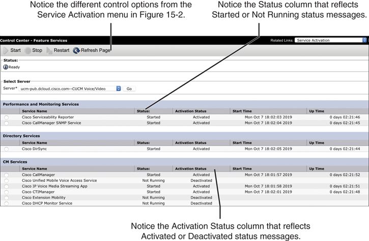
Figure 15-3 Control Center Feature Services Status
The following list identifies all the feature services by category:
Performance and Monitoring Services: Cisco Serviceability Reporter, Cisco CallManager SNMP Service
Directory Services: Cisco DirSync
CM Services: Cisco CallManager, Cisco Unified Mobile Voice Access Service, Cisco IP Voice Media Streaming App, Cisco CTI Manager, Cisco Extension Mobility, Cisco DHCP Monitor Service, Cisco Intercluster Lookup Service, Cisco Location Bandwidth Manager, Cisco Directory Number Alias Sync, Cisco Directory Number Alias Lookup, Cisco Device Activation Service, Cisco Dialed Number Analyzer Server, Cisco Dialed Number Analyzer, Cisco TFTP
CTI Services: Cisco IP Manager Assistant, Cisco WebDialer Web Service, Self Provisioning IVR
Voice Quality Reporter Services: Cisco Extended Functions
Database and Admin Services: Cisco Bulk Provisioning Service, Cisco AXL Web Service, Cisco UXL Web Service, Cisco TAPS Service
Location-based Tracking Services: Cisco Wireless Controller Synchronization Service
Security Services: Cisco Certificate Authority Proxy Function, Cisco Certificate Enrollment Service, Cisco CTL Provider
CDR Services: Cisco SOAP-CDRonDemand Service, Cisco CAR Web Service
As you can see, some services exist as both network services and feature services. The administrator controls the availability of the feature by activating or deactivating the corresponding feature service. Cisco Unified Communications Manager automatically enables the required network services depending on the activated feature services.
Enterprise Parameters
Enterprise parameters are used to define clusterwide system settings, and these parameters apply to all devices and services across all nodes within the entire cluster. After installation of all Cisco Unified Communications Manager nodes and activation of the feature services, enterprise parameter default values should be verified, and modified if required, before deploying endpoints. Keep in mind, however, that you should change enterprise parameters only if you are completely aware of the impact of your modifications or if instructed to do so by the Cisco Technical Assistance Center.
Enterprise parameters can be accessed under the main Cisco Unified Communications Manager menus by selecting Cisco Unified CM Administration from the Navigator drop-down menu in the top-right corner of the screen and then navigating to System > Enterprise Parameter. On the Enterprise Parameters Configuration page, you will find enterprise parameters that are grouped into categories with the current configuration and the default value shown per parameter. Some enterprise parameters specify initial values of device defaults.
When DNS reliance is removed, all host names within enterprise URL parameters must be changed to IP addresses. When DNS reliance is set up during the installation of the Cisco Unified Communications Manager, these addresses will appear within the Enterprise URL Parameters as the URL of the Cisco Unified Communications Manager. Figure 15-4 illustrates the different fields in the Enterprise Parameters Configuration, as well as the URL Parameters settings.

Figure 15-4 Enterprise Parameter Settings Within the CUCM
There are 33 different sections within the enterprise parameters of the Cisco Unified Communications Manager, and there could be between 1 and 21 different parameters within each section. Most parameters can be left as the default values, and any parameters that need to be changed will include instructions to do so in the corresponding deployment guides from Cisco. An example of one such deployment scenario could be enabling Dependency records, which are a feature of the Cisco Unified Communications Manager that allows an administrator to view configuration database records that reference the currently displayed record. Dependency records are useful when you want to delete a configuration entry, such as a device pool, but the deletion fails because the record is still referenced by a depending faculty within the Cisco Unified Communications Manager, such as an IP phone. Without dependency records, you would have to rifle through many different menus and settings to determine where the dependency exists for the device pool that you tried to delete. If the enterprise parameter called Enable Dependency Records is changed from False to True, a record of all setting dependencies is kept within the Cisco Unified Communications Manager and can be accessed by the administrator.
Once dependency records have been enabled, a specific faculty must be selected before the records can be accessed. For example, navigating to System > Device Pool will not allow the dependency records to be accessed, but selecting a specific device pool and entering into the configuration menus will allow access to these records. A Related Links drop-down menu will appear in the top-right corner of the screen, just under the Navigator drop-down menu. Use the drop-down menu to select the Dependency Records option and click the Go button. A Dependency Records Summary popup window will appear with all the dependent records related to that one setting—in this case, the device pool. This summary will include a Record Count and a Record Type with hyperlinks. The hyperlinks will allow the administrator to view specific information within each categorized group. Figure 15-5 illustrates the Dependency Records summary. In this summary, one of the Record Types is Phone, and the Record Count is 8. If the hyperlink were selected for Phone or 8, the resulting data displayed would be a list of the eight phones that have a dependency on this device pool.
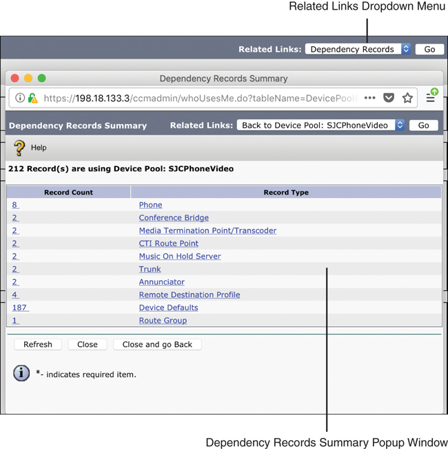
Figure 15-5 Dependency Records Summary Page
Throughout this book I will continue to reference settings within the enterprise parameters settings as other topics are discussed. To obtain additional information about enterprise parameters, navigate to System > Enterprise Parameters and click the question mark symbol at the top-right corner of the Enterprise Parameters Configuration section on the screen. A complete list of all the enterprise parameters, along with a description, will be provided.
Service Parameters
Service parameters are used to define settings for a specific feature service on an individual server. Unlike enterprise parameters, service parameters are defined separately for each server in the cluster and for each feature service enabled on each server, such as the call-processing Cisco CallManager service on the Publisher server. After activation of feature services, service parameter default values should be verified and possibly modified, if required, before deploying endpoints.
To access the service parameters on the Cisco Unified Communications Manager from the Cisco Unified CM Administration, navigate to System > Service Parameters. In the Select Server and Service section, use the drop-down tool beside the Server menu to select a server within the Cisco Unified Communications Manager cluster. Remember that service parameters are specific to each server within the cluster and to each service on that particular server. Once the server has been chosen, a new menu option called Service will appear. Use the drop-down tool next to this menu option to select a feature service on the previously selected server. This will display all the service settings for that specific service on that particular server. The service options in the drop-down list will also identify whether each service listed is Active or Inactive. Figure 15-6 illustrates the menu options for accessing service parameters.
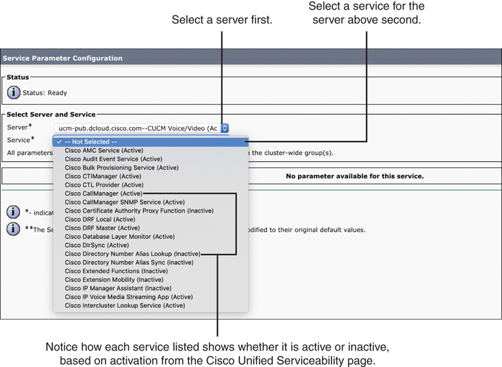
Figure 15-6 Accessing Service Parameters on the CUCM
For each of the feature services listed earlier in this chapter, there is an entire web page of settings within the Cisco Unified Communications Manager. Much like the enterprise parameters, the System Configuration Guide for Cisco Unified Communications Manager will identify which service parameters need to be modified based on special deployment scenarios. The link to access this guide is as follows: https://www.cisco.com/c/en/us/td/docs/voice_ip_comm/cucm/admin/12_0_1/systemConfig/cucm_b_system-configuration-guide-1201/cucm_b_system-configuration-guide-1201_chapter_0101.html. Although not all of these settings are listed in this chapter, three commonly referenced service parameters for the Cisco CallManager service are the following:
T302 Timer: This setting specifies the interdigit timer for variable-length numbers. Reducing the default value will speed up dialing (shorter post-dial delay).
CDR and CMR: Call detail records and call management records are the bases for call reporting, accounting, and billing. The service parameters are used to enable CDRs and CMRs (both are disabled by default). While the CDR service parameter can be easily found by using the search function (the parameter is named CDR Enabled Flag), it is more challenging to find the CMR parameter (the parameter is named Call Diagnostics Enabled).
Clusterwide Parameters (System-Location and Region): This section lists various codecs of voice media-streaming applications. These codecs can be modified or disabled if needed.
By default, not all service parameters are displayed. If you cannot find the service parameter that you want to change, click Advanced to see the complete list of available service parameters. The Change B-Channel Maintenance Status service parameter is an example of a Cisco CallManager service parameter that is not shown by default. Descriptions for all service parameters can be found by clicking the yellow question mark symbol in the upper-right corner, similar to the enterprise parameters. Figure 15-7 illustrates the Service Parameters Configuration page.
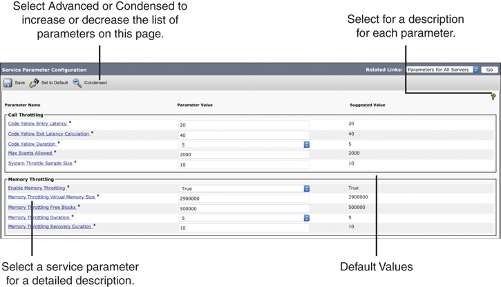
Figure 15-7 Service Parameter Configuration Page
Other Settings
All of the settings discussed in this chapter up to this point need to be configured by an administrator in a greenfield deployment prior to releasing the Cisco Unified Communications Manager into a production network. However, services or enterprise parameters and service parameters can also be enabled or configured in brownfield deployments of the Cisco Unified Communications Manager as the administrator adds functionality to an already-existing solution. Although all of the settings covered so far are foundational to using the Cisco Unified Communications Manager, you might need to configure other settings prior to a greenfield deployment or before expanding a brownfield deployment.
Groups
A Cisco Unified Communications Manager cluster is a collection of physical servers that work as a single IP PBX system. A Cisco Unified Communications Manager cluster may contain as many as 20 server nodes. Of these 20, a maximum of 8 servers may run the Cisco CallManager service to perform call processing in a cluster. Other services, such as dedicated database publisher, dedicated TFTP server, or MOH servers, may also be enabled on a separate server that registers with the cluster. The same holds true for media-streaming applications, such as the audio conference bridge or media termination point (MTP). Each cluster must provide a TFTP service. The TFTP service is responsible for delivering IP phone configuration files to telephones, along with streamed media files, such as MOH and ring files. Therefore, the server that is running the TFTP service can experience a considerable network and processor load. Depending on the number of devices that a server supports, you can run the TFTP service on a dedicated server, on the database publisher server, or on any other server in the cluster.
Cisco Unified Communications Manager groups are used to collect servers within a cluster that run the Cisco CallManager service to provide call-processing redundancy. A Cisco Unified Communications Manager group is a prioritized list of one or more call-processing servers. Architects and sales engineers designing Cisco Unified Communications Manager cluster solutions for customers should consider the following rules prior to building Cisco Unified Communications Manager groups:
Multiple Cisco Unified Communications Manager groups can exist in the same cluster.
Each call-processing server can be assigned to more than one Cisco Unified Communications Manager group.
Each device must have a Cisco Unified Communications Manager group assigned, which will determine the primary and backup servers to which the device can register.
Cisco IP phones register with their primary server. When idle, the IP phones and the Cisco Unified Communications Manager exchange signaling application keepalives. In addition, Cisco IP phones establish a TCP session with their secondary server and exchange TCP keepalives. When the connection to the primary server is lost and no keepalive messages are received by the phone, the IP phone registers to the secondary server. The IP phone will continuously try to reestablish a connection with the primary server even after it has registered to the secondary server. Once a connection has been reestablished, the IP phone will register back to the primary server again.
Two models of redundancy can be configured on the Cisco Unified Communications Manager using groups. A 1:1 Cisco Unified Communications Manager redundancy deployment design guarantees that Cisco IP phone registrations will never overwhelm the backup servers, even if multiple primary servers fail concurrently. However, the 1:1 redundancy design has an increased server count compared with other redundancy designs and may not be cost effective. Figure 15-8 illustrates how a 1:1 redundancy design can be used with Cisco Unified Communications Manager groups.
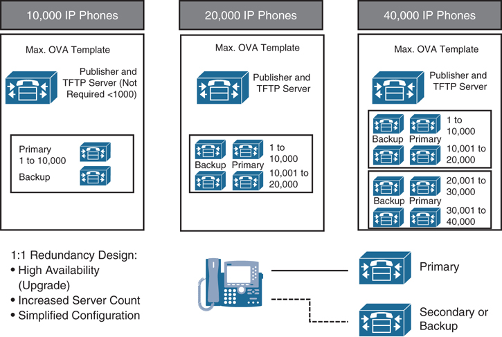
Figure 15-8 Cisco Unified Communications Manager Groups Using 1:1 Redundancy
In the first scenario of Figure 15-8, the two call-processing servers support a maximum of 10,000 Cisco IP phones. One of these two servers is the primary server; the other server is a dedicated backup server. The function of the database publisher and the TFTP server can be provided by the primary or secondary call-processing server in a smaller IP telephony deployment of fewer than 10,000 IP phones. In this case, only two servers are needed in total. When you increase the number of IP phones, you must increase the number of Cisco Unified Communications Manager servers to support those endpoints. Some network engineers may consider the 1:1 redundancy design excessive because a well-designed network is unlikely to lose more than one primary server at a time. With the low possibility of server loss and the increased server cost, many network engineers choose a 2:1 redundancy design.
Although the 2:1 redundancy design offers some redundancy, there is the risk of overwhelming the backup server if multiple primary servers fail. In addition, upgrading the Cisco Unified Communications Manager servers can cause a temporary loss of some services, such as TFTP or DHCP, because a reboot of the Cisco Unified Communications Manager servers is needed after the upgrade is complete. Even with the limitation presented, network engineers use this 2:1 redundancy model in most IP telephony deployments because of the reduced server costs. If a virtual machine with the largest OVA template is used, then the UCS server hosting that VM will be equipped with redundant, hot-swappable power supplies and hard drives. When these servers are properly connected and configured, it is unlikely that multiple primary servers will fail at the same time, which makes the 2:1 redundancy model a viable option for most businesses. Figure 15-9 illustrates how a 2:1 redundancy design can be used with Cisco Unified Communications Manager groups.

Figure 15-9 Cisco Unified Communications Manager Groups Using 2:1 Redundancy
Notice that the first scenario is the same as shown in the 1:1 redundancy in Figure 15-8. When using no more than 10,000 IP phones, there are no savings in the 2:1 redundancy design compared with the 1:1 redundancy design simply because there is only a single primary server. In the scenario with up to 20,000 IP phones, there are two primary servers (each serving 10,000 IP phones) and one secondary server. As long as only one primary server fails, the backup server can provide complete support. If both primary servers failed, the backup server would be able to serve only half of the IP phones. The third scenario shows a deployment with 40,000 IP phones. Four primary servers are required to facilitate this number of IP phones. For each pair of primary servers, there is one backup server. As long as no more than two servers fail, the backup servers can provide complete support, and all IP phones will operate normally.
Device Settings
While enterprise parameters deal with clusterwide settings and service parameters deal with server or service-related settings, device settings include parameters that are tied to individual devices or device pools. In several menus within the Cisco Unified Communications Manager, various device settings can be configured. An administrator can configure device settings under Device > Device Settings or under Device > Phone. In fact, many of the settings under the Phone menu depend on device settings being configured first.
When an administrator is configuring a phone in the Cisco Unified Communications Manager, some minimum settings must be configured before a phone can register. Those settings include Device Pool, Phone Button Template, Common Phone Profile, Owner User ID, Device Security Profile, and SIP Profile. The setting under the Device Pool menu warrants a deeper discussion, so that topic will be discussed more later. The Owner User ID setting is configured under User Management > End User and is required only if the Owner setting is set to User and not Anonymous (Public/Shared Space). The device security profile is configured under System > Security > Phone Security Profile. There are preconfigured nonsecure device security profiles in the Cisco Unified Communications Manager for all supported phone models. Additional phone security profiles need to be configured only if secure phone profiles are going to be used. The rest of the required settings for endpoint registration, which include Phone Button Template, Common Phone Profile, and SIP Profile, can be configured under Device > Device Settings.
The menu options under Device Settings include some preconfigured templates, but administrators can create custom templates for specific deployment scenarios. The sections that follow describe the most commonly used device settings.
Device Defaults
You can use device defaults to set the default characteristics of each type of device that registers with a Cisco Unified Communications Manager. The device defaults for a device type apply to all auto-registered devices of that type within a Cisco Unified Communications Manager cluster. You can set the following device defaults for each device type to which they apply:
Device load
Device pool
Phone button template
When a device auto-registers with a Cisco Unified Communications Manager, it acquires the device default settings for its device type. After a device registers, you can update its configuration individually to change the device settings. Installing Cisco Unified Communications Manager automatically sets device defaults. You cannot create new device defaults or delete existing ones, but you can change the default settings.
Phone Button Template
Phone button templates are used to customize the line keys on a Cisco Unified IP phone. Cisco Unified Communications Manager includes default templates for each Cisco Unified IP phone model because the line keys are different on each phone model type. When you add phones, you can assign one of these templates to the phone or create a template of your own. You can make changes to the custom, nonstandard templates that you created, and you can change the label of the custom phone button template. You cannot change the function of the buttons in the default templates. You can update a custom, nonstandard phone button template to add or remove features; add or remove lines and speed dials; or assign features, lines, and speed dials to different buttons on the phone. You also can change the button labels in the default phone button templates, but you cannot change the function of the buttons in the default templates. If you update a phone template, be sure to inform affected users of the changes. The Programmable Line Key (PLK) feature expands the list of features that can be assigned to the line buttons to include features that are normally controlled by softkeys, such as New Call, Call Back, End Call, and Forward All. If you create a template for a Cisco Unified IP phone, you can change the default template for that phone during auto-registration.
Soft Key Template
Soft keys are the buttons on Cisco Unified IP phones that are located under the display and are usually associated with different menu options. Softkey templates can be used to manage softkeys that are associated with applications such as Cisco Unified Communications Manager Assistant, or features such as Call Back on Cisco Unified IP phones. Cisco Unified Communications Manager supports two types of softkey templates: standard and nonstandard. Standard softkey templates in the Cisco Unified Communications Manager database contain the recommended selection and positioning of the softkeys for an application. Cisco Unified Communications Manager provides the following standard softkey templates:
Cisco Assistant with Feature Hardkeys
Cisco Chaperone Phone with Feature Hardkeys
Cisco Feature with Feature Hardkeys
Cisco Manager with Feature Hardkeys
Cisco Protected Phone with Feature Hardkeys
Cisco Shared Mode Manager with Feature Hardkeys
Cisco User with Feature Hardkeys
Standard User
Standard Chaperone Phone
Standard Feature
Standard Assistant
Standard Protected Phone
Standard Shared Mode Manager
Standard Manager
To create a nonstandard softkey template, you can copy a standard softkey template and modify it. You can add and remove applications, and you can configure softkey sets for each call state. The Softkey Template Configuration window lists the standard and nonstandard softkey templates and uses different icons to differentiate between standard and nonstandard templates. After you have configured a softkey template, you can use any of the following configuration windows to assign the softkey template to devices:
Common Device Configuration (Device > Device Settings > Common Device Configuration)
Phone Configuration for SIP and SCCP phones (Device > Phone > Phone Configuration)
UDP Template Configuration (Bulk Administration > User Device Profiles > User Device Profile Template)
Default Device Profile Configuration (Device > Device Settings > Default Device Profile)
Phone Services
Using Cisco Unified Communications Manager Administration, you can define and maintain the list of IP phone services that can display on supported Cisco Unified IP phone models. IP phone services comprise XML applications or Cisco-signed Java MIDlets that enable the display of interactive content with text and graphics on some Cisco Unified IP phone models. Cisco Unified Communications Manager provides Cisco-provided default IP phone services, which install automatically with Cisco Unified Communications Manager. You can also create customized Cisco Unified IP phone applications for your site. After you configure the services, you can add services to the phones in the database, that is, if they are not classified as enterprise subscriptions, and you can assign the services to the Services, Directory, or Messages buttons/options, if the phone model supports these buttons/options. Users can log in to the Cisco Unified Communications Self Care Portal and subscribe to these services for their Cisco Unified IP phones, so long as these IP phone services are not classified as enterprise subscriptions.
SIP Profile
A Session Initiation Protocol (SIP) profile comprises the set of SIP attributes that are associated with SIP trunks and SIP endpoints. SIP profiles include information such as name, description, timing, retry, call pickup URI, and so on. The profiles contain some standard entries that cannot be deleted or changed.
Device Pool Settings
Configuring device settings the way they are designed in the Cisco Unified Communications Manager is advantageous to administrators. When a phone is being configured in the Cisco Unified Communications Manager, the administrator needs to select only one device setting for a group of settings to apply to a single phone. However, many other settings under the Device > Phone menu still are not affected by the Device Settings menu options. Some of those settings include Media Resource Group List, Network MOH Audio Source, Location, AAR Group, and Network Locale. Although these settings can be configured individually for a phone, they can also be grouped together using a tool called a device pool in the Cisco Unified Communications Manager.
Device pools define sets of common characteristics for devices. The device pool structure supports the separation of user and location information. The device pool contains system, device, and location-related information. The Common Device Configuration window under Device > Device Settings > Common Device Configuration records all the user-oriented information such as type of softkey template that is used and locale information. You should ensure that each device is associated with a device pool and with a common device configuration for user-oriented information. After adding a new device pool to the database, you can use it to configure devices such as Cisco Unified IP phones, gateways, conference bridges, transcoders, media termination points, voicemail ports, CTI route points, and so on. Before you configure a device pool, you must configure the following items if you want to choose them for the device pool:
Cisco Unified Communications Manager Group: This is a required field in the device pool. We already discussed the purpose and model options for Cisco Unified Communications Manager Groups earlier in this chapter. Device pools are used to apply this setting on endpoints.
Date/Time Group: This is a required field. Network Time Protocol (NTP) was discussed in a previous chapter. Cisco Unified IP phones receive their NTP reference from the Cisco Unified Communications Manager. Date/Time groups are used to establish a common time zone, date format, and time format, along with the NTP reference.
Region: This is also a required field. Regions are used to establish the codec selection and per-call bandwidth rate between phones registered to the Cisco Unified Communications Manager. This setting requires a deeper explanation, which is provided in the next section of this chapter.
SRST Reference: This is an optional field. Survivable Remote Site Telephony is a redundancy feature available on Cisco IOS routers that allows Cisco Unified IP phones registered to the Cisco Unified Communications Manager from remote office locations to register to their local router during WAN network failure events. The SRST reference determines where those phones should register during these situations.
Media Resource Group List: This is an optional field. MRGL is a prioritized list of media resource groups. These lists are used to determine which media resource should be used in various situations. Media resources could be Music on Hold (MOH), Conferencing, Annunciator, or other such resources.
Other fields within device pools can be configured beyond those mentioned here; however, the preceding list is a compilation of the most common settings configured in a device pool.
Codec Negotiations Using Regions
An enterprise network uses bandwidth for many different purposes, and all IP-based communication usually crosses the same network edge. You could have voice and video traffic crossing the WAN, while large files are being transferred to an FTP server at a remote location, and other devices are accessing email or other services in the cloud all at the same time. The result is that each of these devices competes for bandwidth across the company’s network. Individual sites of a multisite deployment are usually interconnected by an IP WAN. Bandwidth on WAN links is limited and relatively expensive. Therefore, the goal is to use the available bandwidth as efficiently as possible. You should discourage unnecessary traffic, such as social media sites and personal use, and consider implementing methods for bandwidth optimization. Implementing QoS policies will certainly help during high congestion times across the network, but QoS will not prevent overutilization of bandwidth. Cisco has several Call Admission Control (CAC) mechanisms that can be implemented to control how bandwidth is used across your network.
Before we delve into how to implement CAC on the Cisco Unified Communications Manager, it is important to first understand what happens on the network when bandwidth is overutilized. Assume with this scenario that the WAN can handle up to 1 Mbps total bandwidth. If two endpoints place an audio call using G.711 codec for audio, then they will consume 87.2 kbps; 64 kb are for the payload, and 23.2 kb are for headers. That means that the WAN link can support up to roughly 11 calls, assuming no other network traffic is consuming bandwidth at the time of the calls. So, what happens when the twelfth call attempt is placed? The call isn’t dropped. Rather, this call leg will begin barrowing bandwidth from the other existing calls, and everyone will suffer quality loss during their calls, even with proper QoS in place. This is where CAC comes into the picture. Using CAC in the Cisco Unified Communications Manager allows administrators to control the codec used on a per-call basis dependent on the sites between which calls are placed, as well as the overall bandwidth used when calls are placed across the WAN.
Regions are the first settings on the CUCM you should configure for Call Admission Control. Regions control the codecs used between endpoints when calls are set up. Careful planning should precede implementing regions to avoid call drops and quality issues related to codec mismatch between regions. A specific bandwidth allocation is associated with each audio codec, so you can easily plan and predict how much bandwidth is going to be consumed. G.711 is an uncompressed codec and consumes 87.2 kbps per call with average audio quality. G.729 is a compressed audio codec that consumes only 31.2 kbps but suffers from poorer quality. Other codecs can be compressed or uncompressed and will have varying levels of quality accordingly.
Compression involves utilizing encoding algorithms to reduce the size of digital data. Compressed data must be decompressed to be used. This extra processing imposes computational or other costs into the transmission hardware. Lossless and lossy are descriptive terms used to describe whether or not the data in question can be recovered exactly bit-for-bit, when the file is uncompressed or whether the data will be reduced by permanently altering or eliminating certain bits, especially redundant bits. Lossless compression searches content for statistically redundant information that can be represented in a compressed state without losing any original information. By contrast, lossy compression searches for nonessential content that can be deleted to conserve storage space. Figure 15-10 illustrates the differences between lossless and lossy compression.

Figure 15-10 Compression Types with Regions
When configuring region settings for audio in the Cisco Unified Communications Manager, the administrator simply needs to select the compression type and audio codec preference. Audio media is so predictable that the bandwidth used is based directly on the codec selection. However, video is very greedy and bursty when it comes to bandwidth consumption. Video codecs do not have a specific set bandwidth rate to them like audio codecs. A video call can be placed using 480p30 resolution at 384 kbps or at 2 Mbps. However, using a higher codec can provide better efficiency and thus consume less bandwidth. Therefore, when configuring regions in the Cisco Unified Communications Manager, administrators do not select a codec specifically; instead, they set the per-call bandwidth rate that is allowed between each site. There are two fields to configure video bit rates in the Regions settings page:
The Video Calls column has to do with UC endpoints that can place video calls, such as the 8845 and 8865 IP video phones and Jabber client.
The Immersive Video Calls column has to do with any Cisco Telepresence video endpoint, such as the DX80, MX700, SX80, or Webex endpoints.
Table 15-2 identifies the average bandwidth consumption for various video resolutions per the four main video codecs. The bandwidth rates represented in the table do not reflect any overhead calculations.
Table 15-2 Average Bandwidth Consumption per Video Codec
Codec |
H.261 |
H.263 |
H.264 |
H.265 HEVC |
|---|---|---|---|---|
Bandwidth rate at 480p30 |
512 kbps |
384 kbps |
256 kbps |
128 kbps |
Bandwidth rate at 720p30 |
N/A |
1024 kbps |
768 kbps |
384 kbps |
Bandwidth rate at 1080p30 |
N/A |
1536 kbps |
1024 kbps |
512 kbps |
Bandwidth rate at 1080p60 |
N/A |
N/A |
2048 kbps |
1024 kbps |
Bandwidth rate at 4Kp60 |
N/A |
N/A |
N/A |
2048 kbps |
Follow these steps to configure region information on the Cisco Unified Communications Manager:
Step 1. In a web browser, navigate to the address of the Cisco Unified Communications Manager followed by /ccmadmin and log in. For example, if the address were cucm.company.com, you would navigate to https://cucm.company.com/ccmadmin.
Step 2. Navigate to System > Region Information > Region and click the Find button. One region, called Default, will exist.
Step 3. Click the Add New button to create a new region.
Step 4. Give it a name, such as RTP_Region, and click the Save button.
Step 5. Two other sections will open below: Region Relationships and Modify Relationship to Other Regions. Under the second section, select your region from the list in the Regions box and modify the codec selection as mentioned here:
Audio Codec Preference List: Use System Default (Factory Default low loss)
Maximum Audio Bit Rate: 64 kbps (G.722, G.711)
Maximum Sessions Bit Rate for Video Calls: 2048 kbps
Maximum Sessions Bit Rate for Immersive Video Calls: 2048 kbps
Step 6. Click the Save button when finished. This action establishes the codec selection between endpoints using the same RTP_Region.
Step 7. You can create additional regions and determine a codec selection when calling between these regions. For example, on the same page, select the Default region and change the codec selections as noted here:
Audio Codec Preference List: Factory Default Lossy
Maximum Audio Bit Rate: 8 kbps (G.729)
Maximum Sessions Bit Rate for Video Calls: 384 kbps
Maximum Sessions Bit Rate for Immersive Video Calls: 384 kbps
Step 8. Click the Save button again.
Both regions should be added to the Region Relationships section, but different codecs will be listed for each. When an endpoint assigned the RTP_Region calls an endpoint assigned the Default region, a different audio compression, codec, and video bandwidth rate will be used, as compared to two endpoints that are both assigned the RTP_Region. Region settings are bidirectional; therefore, any settings configured in one region will automatically be reflected in other regions. Locations play hand-in-hand with regions, but that discussion will be saved for a later chapter. Figure 15-11 illustrates the region settings as described in the preceding steps.
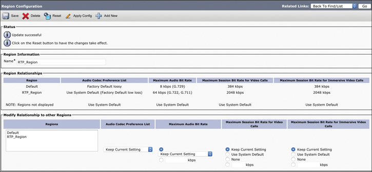
Figure 15-11 Region Settings
Exam Preparation Tasks
As mentioned in the section “How to Use This Book” in the Introduction, you have a couple of choices for exam preparation: the exercises here, Chapter 32, “Final Preparation,” and the exam simulation questions in the Pearson Test Prep Software Online.
Review All Key Topics
Review the most important topics in this chapter, noted with the Key Topics icon in the outer margin of the page. Table 15-3 lists a reference of these key topics and the page numbers on which each is found.
Table 15-3 Key Topics for Chapter 15
Key Topic Element |
Description |
Page Number |
|---|---|---|
List |
CUCM Network Services |
348 |
List |
CUCM Feature Services |
350 |
Paragraph |
Enterprise Parameters Explained |
351 |
List |
Cisco CallManager Service Parameter Settings |
354 |
List |
Rules for Creating Cisco Unified Communications Manager Groups |
355 |
List |
Device Pool Menu Options |
361 |
Average Bandwidth Consumption per Video Codec |
363 |
|
Steps |
Configuring Regions in the CUCM |
363 |
Define Key Terms
Define the following key terms from this chapter and check your answers in the glossary:
Q&A
The answers to these questions appear in Appendix A. For more practice with exam format questions, use the Pearson Test Prep Software Online.
1. List the eight different feature service categories available on the Cisco Unified Communications Manager.
2. Define enterprise parameters.
3. What are the three most important CallManager service parameters mentioned in this book?
4. What are the two models of redundancy that can be configured on the Cisco Unified Communications Manager using groups?
5. List and define the two main compression types available through CUCM regions.