
Chapter 18
Cisco Unified Communications Manager Call Admission Control (CAC)
This chapter covers the following topics:
Endpoint Addressing: This topic will overview dial plan components on the Cisco Unified Communications Manager and explain directory numbers and directory URIs.
Call Privileges: This topic will introduce how partitions and calling search spaces within the Cisco Unified Communications Manager can be used for a controlled cost of service (COS) (not to be confused with class of service [CoS]) to prevent hairpinning and establish privileges for different users. This section will also cover how to control calls through bandwidth management using location-based Call Admission Control (CAC).
Call Coverage: This topic will illustrate how to use hunt pilots, hunt lists, line groups, shared lines, and call forward settings in the Cisco Unified Communications Manager to establish better call coverage within a production environment.
The preceding three chapters discussed how to set up the Cisco Unified Communications Manager initially, how to import users, and how to register endpoints. This chapter will begin examining how to control the voice and video communications environment using cost of service (COS) and Call Admission Control (CAC) tools built into the Cisco Unified Communications Manager. Topics discussed in this chapter include the following:
Endpoint Addressing
Numeric Addresses
Alphanumeric Addresses
Call Privileges
Partitions and Calling Search Spaces (CSS)
Time of Day (ToD) Routing
Location-Based CAC Bandwidth Requirements
Call Coverage
Hunting (Line Group Members, Hunt Lists, Line Groups, Hunt Pilots)
Call Hunting Operation and Call Flow
Call Queuing Settings
This chapter covers the following objectives from the Cisco Collaboration Core Technologies v1.0 (CLCOR 350-801) exam:
4.1 Describe the Cisco Unified Communications Manager digit analysis process
4.2 Implement toll fraud prevention on Cisco Unified CM
4.3 Configure globalized call routing in Cisco Unified CM
4.3.a Route patterns (traditional and +E.164 format)
4.3.e SIP route patterns
“Do I Know This Already?” Quiz
The “Do I Know This Already?” quiz allows you to assess whether you should read this entire chapter thoroughly or jump to the “Exam Preparation Tasks” section. If you are in doubt about your answers to these questions or your own assessment of your knowledge of the topics, read the entire chapter. Table 18-1 lists the major headings in this chapter and their corresponding “Do I Know This Already?” quiz questions. You can find the answers in Appendix A, “Answers to the ‘Do I Know This Already?’ Quizzes.”
Table 18-1 “Do I Know This Already?” Section-to-Question Mapping
Foundation Topics Section |
Questions |
|---|---|
Endpoint Addressing |
1–3 |
Call Privileges |
4–6 |
Call Coverage |
7–10 |
Caution
The goal of self-assessment is to gauge your mastery of the topics in this chapter. If you do not know the answer to a question or are only partially sure of the answer, you should mark that question as wrong for purposes of the self-assessment. Giving yourself credit for an answer you correctly guess skews your self-assessment results and might provide you with a false sense of security.
1. What tool exists on Cisco IOS gateways to allow administrators to implement call privileges?
Partitions
CSSs
COR
Call Policy
2. Which of the following is a method of mapping PSTN numbers to DNs using translation patterns on the CUCM?
+E.164 addressing
Two-stage dialing
E.164 addressing
Off-net dialing
3. What is the maximum number of directory URIs that can be set per DN?
1
2
5
10
4. Which of the following is an application of call privileges in the CUCM?
Used to control per-call bandwidth and total bandwidth throughout the enterprise network
Used to group endpoints together so that incoming calls are not dropped
Used to give priority over some calling devices, such as a manager’s phone, over others during high congestion times
Used to route calls to the same number in different ways based on different calling devices
5. If both line and device CSSs are configured on a CTI port, what order are aliases and route patterns searched?
Line CSS partitions based on order listed, then device CSS based on order listed
Line CSS partitions, then device CSSs, but the order listed does not matter
Device CSS partitions based on order listed, then line CSSs based on order listed
Device CSS partitions, then line CSS, but the order listed does not matter
6. What location should be used for inter-cluster trunks on the CUCM?
Hub_None
Shadow
Phantom
Custom
7. Which of the following call coverage areas are features typically implemented for individuals? (Choose three.)
Call Forward
Shared Lines
Call Pickup
Hunting
Partitions
Calling Search Spaces
8. What is the correct order of configuration for hunting on the Cisco Unified Communications Manager?
Line Group Members > Line Groups > Hunt List > Hunt Pilot
Hunt Pilot > Hunt List > Line Group > Line Group Members
Line Group Members > Hunt List > Line Group > Hunt Pilot
Hunt Pilot > Line Group > Hunt List > Line Group Members
9. When hunting is used on the CUCM from a call forward, and all possible line group members have been searched without making a connection, which of the following final forwarding options is likely to be used?
All calls will stop hunting, regardless of any other setting.
A final forwarding number must be configured in the hunt pilot.
The call will return to the call forwarding hunt pilot number that initiated the hunt, and the whole process will start over again.
If Use Personal Preference is selected, the call is routed to the number that is configured for CFNC on the phone line that invoked the call to the pilot number.
10. When you use queuing with hunting, which of the following reasons could cause the call to be disconnected and never placed in the queue?
A line group member becomes available while in the queue.
No line group members are logged in or registered.
Hunt pilot maximum wait time in the queue has expired.
The queue will never disconnect callers for any reason.
Foundation Topics
Endpoint Addressing
In my experience, when I mention the term dial plan, many people are not acquainted with the term. However, all people use dial plans daily. A dial plan is a carefully planned design for reaching devices and services in a Collaboration network and in the public switched telephone network (PSTN). Endpoint addressing covers how you assign individual or blocks of telephone numbers or URIs to endpoints. A dial plan must include information on how to call other endpoints. These dial rules typically differ depending on the type of call, whether it be an intra-site, inter-site, external, emergency, or other type of call. The dial plan specifies the format in which connected parties are presented and determines the dial plan features and applications such as classes of service and call coverage. Finally, a dial plan defines how calls are routed. This process includes analyzing the received digits, finding the best-matching entry in the call-routing table, choosing the device to which the call should be sent, and determining what to do if that device is busy or not reachable.
The larger an enterprise deployment and the more different dialing domains exist, the more an engineer has to know to design an appropriate dial plan. In general, an engineer must know about the possible types of endpoint addressing, such as numbers versus URIs, how internal and external numbers relate to each other, and the E.164 format that is used in the PSTN. In addition, the engineer must be able to assess the dialing habits of all the dialing domains that exist locally in the enterprise deployment and how to identify and avoid overlapping numbers. The engineer must also have the skills to analyze emergency dialing requirements and to implement methods for PSTN cost avoidance.
Dial plans can be very complex and involve a lot of different geographic areas and devices. Therefore, good documentation is required and should include information that is relevant to end users as well as implementation details that are relevant for administrators and support personnel. Information that is relevant to end users includes the dial habits that are applicable to their site, the dial habits that apply when they roam to another site, and their calling privileges. Documentation is useful only when it is up to date, accessible, and when everyone knows where to find it and when it has been updated. Therefore, you should make sure that all documentation is well defined and that clear responsibilities and processes are in place to ensure that the documentation is accurate; simple to understand; and available to users, administrators, and support teams.
Two aspects must be included in any dial plan documentation: the person who is responsible for each part of the documentation and how changes are approved, implemented, and communicated. Accurate documentation is the basis for troubleshooting, monitoring, planning changes and enhancements, and redesigning.
The North American Numbering Plan (NANP) is a standardized national dial plan that assigns individual or blocks of telephone numbers, which are called E.164 addresses, to physical lines or circuits. This telephone network is based on a 10-digit dial plan that consists of 3-digit area codes and a 7-digit subscriber number known as the telephone number. That 7-digit subscriber number can be further broken down into a 3-digit Central Office Code and a 4-digit line number, also referred to as the subscriber number.
Features within a telephone switch, such as Centrex, support a custom 5-digit dial plan for specific customers who subscribe to that service. PBXs also support variable-length dial plans that contain from 3 to 11 digits. Dialing internationally will also require variable-length numbers to be dialed depending on the country being called. Dial plans contain specific dialing patterns so that users can reach a particular telephone number. Access codes, area codes, specialized codes, and combinations of dialed digits are all part of any particular dial plan. Dial plans that are used within voice-capable routers specify how to determine which digits and how many digits to store in each configuration. If the dialed digits match the configured number and patterns, the call is processed for forwarding.
Dial plan design requires knowledge of the network topology, current telephone-number dialing patterns, proposed router and gateway locations, and traffic-routing requirements. No standard protocol is defined for the dynamic routing of E.164 telephony addresses. VoIP dial plans are configured statically and are managed on call processing devices such as the Cisco Unified Communications Manager, Cisco gateways, and the Cisco Unified Border Element (CUBE). A well-designed dial plan consists of the following components:
Endpoint Addressing (Numbering Plan): Assigning directory numbers (DNs) to all endpoints (such as IP phones, fax machines, and analog phones) and applications (such as voicemail systems, auto attendants, and conferencing systems) enables you to access internal and external destinations.
Call Routing and Path Selection: Depending on the calling device, you can select different paths to reach the same destination. You can also use a secondary path when the primary path is unavailable, such as transparently rerouting a call over the PSTN during an IP WAN failure.
Digit Manipulation: In some cases, the dialed string must be manipulated before routing a call, such as when a call that was originally dialed by using the on-net access code is rerouted over the PSTN. Another example is when an abbreviated code, such as 0 for the operator, is expanded to an extension. This necessity can occur before or after a routing decision is made.
Calling Privileges: You can assign different groups of devices to different classes of service, by granting or denying access to certain destinations. For example, you might allow lobby phones to reach only internal and local PSTN destinations but give executive phones unrestricted PSTN access.
Call Coverage: You can create special groups of devices to process incoming calls for a certain service, according to different rules (top-down, circular hunt, longest idle, or broadcast). This approach also ensures that calls are not dropped without being answered.
Call routing and path selection along with digit manipulation will be covered in more detail in the next chapter. Figure 18-1 illustrates the essence of a scalable endpoint-addressing scheme that logically includes geographical information as part of the endpoint directory number.
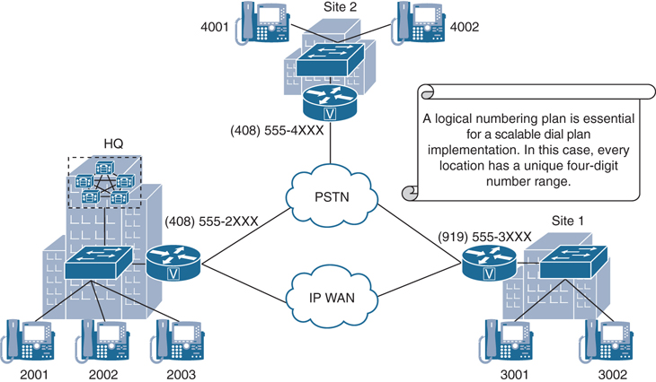
Figure 18-1 Dial Plan Components and Functions
In Figure 18-1, the first digit of every endpoint’s assigned directory number also represents its location. The digit 2 represents Headquarters, 3 represents Site 1, and 4 represents Site 2. All endpoints use the same extension length of four digits. Variable extension lengths and overlapping endpoint addresses can make call routing, path selection, or general dial plan implementation much more complex. Therefore, it is best to avoid such dial plans, as demonstrated in this figure.
An important part of every dial plan implementation is call routing and path selection. Many factors can be considered when deciding which path to take to connect two endpoints via WAN or PSTN. In Figure 18-1, the WAN connection has priority when establishing calls between Headquarters and Site 1. If the WAN is unavailable or its bandwidth is exhausted, calls can be rerouted via the PSTN gateway.
The measure of a good dial plan implementation is realized when the end user does not realize which path was taken to establish the call. A core function to provide this transparency is digit manipulation. Many situations require manipulation of called- or calling-party numbers. Figure 18-2 illustrates two scenarios where digit manipulation is required. In the first scenario, a user on phone 2003 may dial 4002 to reach a user in Site 2. Headquarters and Site 2 are connected via PSTN only, so the dialed number 4002 must be expanded to a complete PSTN number so that the PSTN can successfully route the call. Consider the second scenario where an outside PSTN phone dials (919) 555-3001. That complete PSTN called-party number of an incoming call at Site 1 would need to be trimmed to the 3001-extension length of four digits.

Figure 18-2 Digit Manipulation Scenarios
In most collaboration infrastructure deployments, some type of calling privilege is implemented within a location, between locations, and for calls to the PSTN. Calling privileges are typically implemented according to the called and calling numbers. Using Figure 18-2 as an example, the user on phone 2001 could be configured to allow the establishment of a call to Site 2 via the PSTN, whereas the user on phone 2002 could be restricted to not have sufficient privileges to establish calls via the PSTN.
Some call coverage settings provide functions to process calls that would otherwise be unanswered or provide service numbers through which calls can be distributed among a group of people. Hunt pilot numbers can be created so that calls to a pilot number are distributed among all members of a group based on a defined hunting algorithm. Call coverage can also be configured to forward calls to different numbers, depending on the reason for not being able to process the call, such as Busy, No Answer, and so on, and based on the origin of the call, such as on-net or off-net.
This chapter will delve deeper into the endpoint addressing, call privilege, and call coverage components of a dial plan. Table 18-2 compares the dial plan configuration elements of the Cisco Unified Communications Manager, a Cisco IOS gateway, and the Cisco Expressway series per main component.
Table 18-2 Comparison of Dial Plan Configuration Elements
Dial Plan Component |
Cisco Unified Communications Manager |
Cisco IOS Gateway |
Cisco Expressway Series |
|---|---|---|---|
Endpoint Addressing |
Directory Number, Directory URI |
ephone-dn, voice register pool |
IP Address, H.323 ID, E.164 Alias, Directory URI, Service Prefix |
Call Routing and Path Selection |
Route Patterns, SIP Route Patterns, Route Groups, Route Lists, Trunks |
Dial Peers |
Search Rules, Zones |
Digit Manipulation |
Translation Patterns, Transformation Patterns, Route Patterns |
Voice Translation Profiles and Rules, Dial Peer Settings |
Transforms, Call Policy, FindMe |
Call Privileges |
Partitions, Calling Search Spaces, ToD |
COR |
Call Policy |
Call Coverage |
Hunt Pilots, Line Groups, Hunt Lists, Shared Lines, Call Forward settings |
Dial Peers, Hunt Groups, Call Applications |
FindMe |
Numeric Addresses
To reach internal endpoints such as IP phones, fax machines, and applications, such as voicemail systems, auto-attendants, and conferencing systems, an engineer must assign at least one directory number to each endpoint. In addition, directory URIs can be added as aliases to directory numbers. Calling a configured directory number or directory URI will allow a user to reach the corresponding device.
The first decision an engineer must make is the length of the internally used extension. The number of required extensions influences whether the engineer will choose longer or shorter extensions. Four-digit extensions allow up to 10,000 endpoints to be addressed within a single enterprise deployment. Typically, the phones should also be reachable from the PSTN. Internal endpoint addressing can be mapped to PSTN numbers for off-net connectivity in two ways:
Two-Stage Dialing: With two-stage dialing, all endpoints share a single PSTN number. When a PSTN user wants to call an internal endpoint, the PSTN user calls the PSTN number of the target company. The communications system, such as the Cisco Unified Communications Manager, accepts the call either by routing the call to an attendant’s extension or by answering the call with an IVR script that allows the caller to then enter the extension of the desired internal user.
Direct Inward Dialing (DID): With DID, each internal phone has its own PSTN number. Ideally, the least significant digits of the external DID range match the internally used extension numbers (1:1 mapping). If a corresponding DID range is not available and your PSTN provider assigns different external numbers to you, you must map each external number to an internal extension and translate the number accordingly.
The E.164 number format is used in the PSTN environment. E.164 numbers start with a country code, and they can have a maximum of 15 digits. International phone numbers are usually written with a plus sign (+) before the phone number to indicate that the number is in international E.164 format. Such numbers are referred to as +E.164 numbers. H.323 does not support +E.164 dialing. To actually dial a PSTN number from a normal fixed-line phone, you must use the appropriate access code. Every country has both a national access code, which is used to dial a national number without the country code, and an international access code, which is used to dial out of the country. To indicate that an IP call should be sent to the PSTN from an IP PBX, such as the Cisco Unified Communications Manager, instead of being routed within the enterprise network, a PSTN access code is often configured and must be dialed first to reach an outside line. Calls within an enterprise IP network are referred to as on-net calls. Calls that leave the IP network and traverse the PSTN network are referred to as off-net calls. Figure 18-3 illustrates how 4-digit internal directory numbers are mapped 1:1 to external +E.164 numbers.

Figure 18-3 Endpoint Addressing by Numbers
Alphanumeric Addresses
Directory numbers are assigned to a phone line, and then directory URIs are assigned to a directory number. Therefore, a directory URI cannot exist unless a directory number exists first. The format of a standard URI is different from the format of a URI in the Cisco Unified Communications Manager. A standard URI takes the form host@<Fully_Qualified_Domain_Name>, such as [email protected]. Email addresses are a common use of standard URIs where the domain must be qualified against an authoritative server, such as the mail server. A directory URI on the Cisco Unified Communications Manager has the same look as a standard URI, but it takes the form user@domain or user@ip_address. Because a directory URI is not assigned to a phone, the “domain” portion of the alias does not have to be qualified. The behavior of a directory URI is also slightly different on the Cisco Unified Communications Manager than standard URIs in a typical networked environment. Cisco has renamed the components that make up a directory URI. The domain portion of the directory URI is also referred to as the “host” portion within the Cisco Unified Communications Manager.
Out of the box, the user portion of a directory URI is case sensitive. This has to do with the characters that are considered digits within the Cisco Unified Communications Manager. Any digit 0–9; plus special characters question mark (?), dollar sign ($), exclamation mark (!), percent sign (%), ampersand (&), underscore (_), tilde (~), equal sign (=), backslash (), brackets ([ ]), plus sign (+), dash (-), caret (^), asterisk (*), comma (,), dot (.), forward slash (/), and pound sign (#); and the capital letters A–D are all considered to be of numeric value. Under Cisco Unified Communications Manager Administration, in the Enterprise Parameters Configuration menu, there is a parameter called URI Lookup Policy. The default value to this setting is Case Sensitive, which is what makes the letters A–D represent numbers. Changing this setting to Case Insensitive changes the user portion of the directory URI so that it’s case insensitive, therefore also changing the letters A–D away from numeric status.
The host, or domain, portion of the directory URI is always case insensitive. Acceptable characters in the host portion of the directory URI include the letters a–z, A–Z, numbers 0–9, hyphens, and dots. The host portion must contain at least two characters, it cannot start or end with the hyphen character, nor can it contain two consecutive dots. Table 18-3 identifies all the characters that are supported in both the user and domain portions of a directory URI.
Table 18-3 Directory URI Characters Supported
|
User Portion |
Domain (Host) Portion |
|---|---|---|
Letters |
a–z, A–Z |
a–z, A–Z |
Special Characters |
! $ % & * _ + ~ - = ? ’ , . / |
- . |
Numbers |
0–9 |
0–9 |
There are two ways to place calls to URIs from endpoints that support URI dialing. The first method is by dialing a full directory URI. This method of dialing uses both the user and domain portions of the URI address and is always supported. This method is required when calling the URI of an endpoint outside of the enterprise domain, such as Webex.com. The second method of dialing by URI is by dialing only the user portion. The Cisco Unified Communications Manager will not allow URIs to be dialed by only the user portion unless the organization top-level domain (OTLD) is configured under the enterprise parameters. This is where the case sensitivity setting comes into play. If a user were to dial BAD2003, and the URI Lookup Policy was set to Case Sensitive, the Cisco Unified Communications Manager would see this alias as a directory number, not a directory URI, and no domain would be appended to it. This may impact call routing if the alias only existed within a directory URI. However, changing the URI Lookup Policy to Case Insensitive would allow this alias to be routed as a directory URI. The domain that existed in the OTLD would be appended, and the call would be routed providing a match was found. Ideally, all URIs that are applied to endpoints of a Cisco Unified Communications Manager cluster use the same, globally unique host portion. If you use the same host portion in different clusters, calls between these clusters work only if you implement URI synchronization. URI synchronization is an application of the ILS and GDPR.
As mentioned before, URIs are not directly applied to a phone or phone line, but they are associated with a directory number. When a call is placed to a locally configured URI, the Cisco Unified Communications Manager routes the call to the associated directory number. There are two places where directory URIs can be configured in the Cisco Unified Communications Manager. Directory URIs are assigned at the Directory Number configuration page or at the End User configuration page. Directory URIs set at the End User configuration page will be placed automatically in the Device URI partition, which is a default partition that exists within the Cisco Unified Communications Manager, and this setting cannot be changed. URIs set at the Directory Number configuration page allow you to set the partition to anything, including the None partition, and you can change this setting at any time. You can also set up to five directory URIs per directory number, as long as one of the directory URIs is set as the primary.
Directory numbers can be individually managed under Cisco Unified Communications Manager Administration by navigating to Call Routing > Directory Number. Search for a specific directory number or click Find to view all the available entries. Click the Add New button to configure a new directory number.
After the directory number has been configured, whether with the provisioned phone, end user, or manually, other line settings can now be configured. Many of these settings will be discussed as this chapter progresses. Scroll down to the Directory URIs section. Enter a full URI address in the URI box, and select a partition from the Partition drop-down box. Click on the Add Row button when finished. A new line appears, but the directory URI is added to this directory number. Click Save when finished.
To add a directory URI to an end user, navigate to User Management > End User. Select the end user to be modified, whether this is an LDAP synchronized user or not. In the User Information section, locate the directory URI setting and enter the appropriate value in the box beside it. Click Save after the setting has been configured. Figure 18-4 illustrates where to configure the directory URI settings on the Cisco Unified Communications Manager.

Figure 18-4 Directory URI Settings on the CUCM
Call Privileges
Calling privileges are configured to control which call-routing table entries are accessible from a particular endpoint, such as a phone, gateway, or trunk. The primary application of calling privileges is the implementation of cost of service (COS). Cost of service (COS) should not be confused with class of service (CoS). Class of service is a Layer 2 QoS mechanism that is specific to IP routing across the network. Cost of service (COS) is specific to the Cisco Unified Communications Manager, and it is typically used to control telephony charges when calls are routed through the PSTN by blocking costly service numbers and international calls for some users. COS is also used to protect the privacy of some users, such as to disallow direct calls to managers except through their assistants.
Calling privileges can also be used to implement special applications, such as routing calls to the same number in different ways based on different calling devices. For example, in a selective PSTN breakout in a multisite environment with PSTN gateways at each site, PSTN route patterns should always be directed toward the associated local PSTN gateway. Therefore, the same route patterns must exist multiple times—once per site, in this example. Only the site-specific route patterns should be accessible by the devices at their respective site. Another application is time-of-day routing, in which calls take different paths depending on when the call is placed. Figure 18-5 illustrates the concept of using calling privileges for implementing special applications.
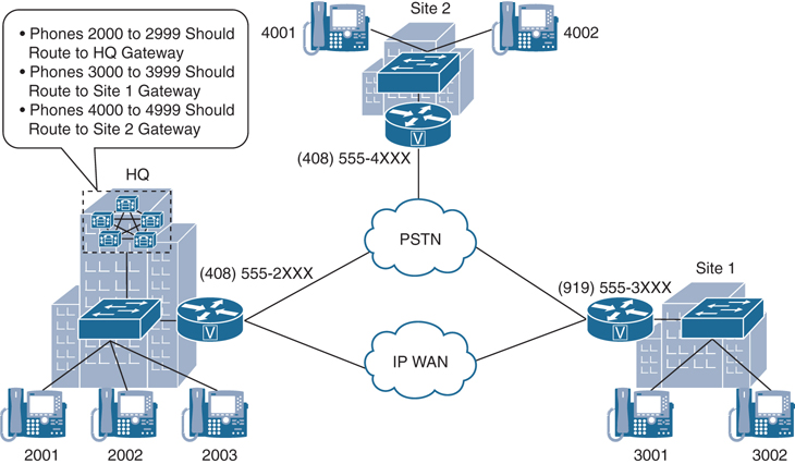
Figure 18-5 Using Calling Privileges for Implementing Special Applications
Calling classes are most commonly used to control tolled calling environments, so that employees are only capable of placing tolled calls depending on what their position in the company requires. Tolled calls can be divided into four categories: Internal, Local, Long Distance, and International. A typical COS implementation will align each of these privilege classes with its allowed destinations. Each calling privilege class can then be assigned to specific devices or users. Table 18-4 identifies each calling privilege class and its associated allowed destinations.
Table 18-4 PSTN Calling Privilege Class Map
Calling Privilege Class (COS) |
Allowed Destinations |
|---|---|
Internal |
Internal Emergency |
Local |
Internal Emergency Local PSTN |
Long Distance |
Internal Emergency Local PSTN Long-Distance PSTN |
International |
Internal Emergency Local PSTN Long-Distance PSTN International PSTN |
In Table 18-4, internal calls are IP-based and have no cost associated with them. Therefore, every class has internal access as an allowed destination for calling. The Internal class is also allowed emergency calls across the PSTN for obvious reasons, but all other PSTN access is restricted. The Local class adds permission for local PSTN calls but is still restricted from placing long-distance or international calls across the PSTN. The Long Distance class is also allowed long-distance PSTN calls, and the International class is not restricted from any type of PSTN call.
Partitions and Calling Search Spaces
A partition is a group of dialable patterns with identical accessibility. A calling search space (CSS) defines which partitions are accessible to a particular device. Another way of looking at partitions and CSSs is that partitions affect inbound called numbers, whereas CSSs affect outbound calling devices. A device can call only those call-routing table entries that are in partitions included in the CSS of the device. Partitions are assigned to call-routing targets—that is, any entry of the call-routing table, including voicemail ports, directory numbers, route patterns, and translation patterns. CSSs are assigned to the sources of call-routing requests, such as phone lines, gateways, trunks, voicemail ports, and applications. By default, all entities that can be configured with a partition are automatically in the <None> partition, also referred to as the null partition, and all entities that can be configured with a CSS are automatically assigned the <None> CSS. The <None> partition allows access to any call-routing sources regardless of the CSS of that call-routing source, and the <None> CSS provides access to no partitions except the <None> partition. By default, no partitions or CSSs are assigned, and all entities are associated with the null partition and <None> CSS. Therefore, all calls are possible for all calling sources by default. Figure 18-6 illustrates how partitions and CSSs operate within the Cisco Unified Communications Manager environment.
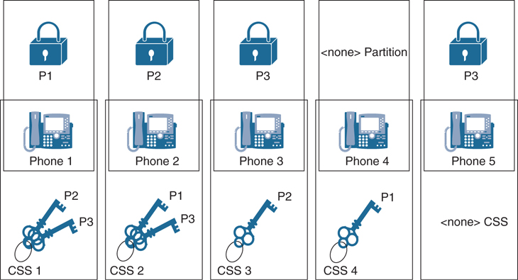
Figure 18-6 Partition and CSS Operation in the CUCM
Several analogies have been created over the years to try to explain the relationship between partitions and CSSs. None have conveyed this information as well as the analogy of locks and key rings, as illustrated in Figure 18-6. The locks represent partitions that an administrator has applied to phone lines. The key rings represent the CSSs. Each key on a key ring represents a different partition associated with that CSS and therefore provides access to that partition. CSSs can be applied to either the phone line or to the phone itself.
In Figure 18-6, Phone 1 is configured as a member of the P1 partition, Phone 2 is in the P2 partition, and Phone 3 and Phone 5 are in the P3 partition. Phone 4 remains in the <none> partition because this phone has not been assigned to any other partition. Following the analogy of locks and keys, there are three different locks (P1, P2, and P3). Locks are a great symbol for partitions because when a phone is assigned to a partition, that phone is secured so that no other phone can call it without appropriate permission. With only the partitions (locks) in place, none of the phones can contact any of the other phones except for Phone 4, which is in the <none> partition. Any device in the <none> partition can be contacted by any other device under any circumstance. Even though Phone 3 and Phone 4 are in the same partition, they cannot call one another because neither phone has permission to call P3. To assign calling privileges, CSSs must also be assigned to each phone.
The CSSs are represented as key rings. Each key on a key ring represents the partition that key ring can access. Phone 1 has a key ring with P2 and P3 keys. Phone 2 has a key ring with P1 and P3 keys. Phone 3 has a key ring with only one key to P2. Phone 4 has a key ring with only one key to P1, and Phone 5 has no keys. As a result of this implementation of partitions and CSSs, the following effective permissions apply:
Phone 1: Phone 1 has access to all devices in the <none> partition, which includes Phone 4 from this example. In addition, Phone 1 can access devices in the P2 and P3 partitions because it has the appropriate keys. Therefore, Phone 1 can access Phone 2, Phone 3, Phone 4, and Phone 5. However, Phone 1 cannot access any other devices in the P1 partition if any existed.
Phone 2: Like Phone 1, Phone 2 has access to all devices in the <none> partition, which includes Phone 4 from this example. In addition, Phone 2 can access devices in the P1 and P3 partitions because it has the appropriate keys. Therefore, Phone 2 can access Phone 1, Phone 3, Phone 4, and Phone 5. However, Phone 2 cannot access any other devices in the P2 partition if any existed.
Phone 3: Like all other phones, Phone 3 has access to all devices in the <none> partition, which includes Phone 4 from this example. In addition, Phone 3 can access devices in the P2 partition because it has the appropriate key. Therefore, Phone 3 can access Phone 2 and Phone 4. However, Phone 3 cannot access any devices in the P1 or P3 partitions.
Phone 4: Like all other phones, Phone 4 has access to all devices in the <none> partition, which includes itself from this example. In addition, Phone 4 can access devices in the P1 partition because it has the appropriate key. Therefore, Phone 4 can access Phone 1 and itself, which is of no practical importance because phones don’t usually place a call to themselves.
Phone 5: Like all other phones, Phone 5 has access to all devices in the <none> partition, which includes Phone 4 from this example. Phone 5 cannot access any other partitions because it is still part of the <none> CSS. Therefore, Phone 5 can access only Phone 4.
To summarize the analogy that is used in Figure 18-6: partitions are like locks, which can be unlocked only by an appropriate key. CSSs are like key rings that include the specified keys for the appropriately assigned partitions. If no partition (lock) is applied to a device, all other devices can access that device. If no CSS (key ring) is present, only devices that do not have a partition (lock) assigned can be accessed.
Now that we’ve established a basic understanding of partitions and CSSs, it is important to understand how these COS mechanisms affect call-routing decisions within the Cisco Unified Communications Manager. Assume a phone has a CSS containing two partitions called Chicago and San Jose. The Chicago Partition contains a phone with the directory number 3001 assigned to Phone 2-1. The San Jose partition contains a phone with the directory number 2001 assigned to Phone 1-1. When the user with the CSS assigned to it places a call to directory number 3001, which is the directory number of Phone 2-1, the Cisco Unified Communications Manager performs a call-routing lookup of the number 3001 through the partitions that are configured in the CSS of the calling phone: Chicago and San Jose. The Cisco Unified Communications Manager finds a match in the Chicago partition because the directory number 3001 of Phone 2-1 is assigned to this partition. Because no other matches exist, routing is complete, and Phone 2-1 rings. This example is pretty straightforward and in line with how call routing has been explained up to this point.
A CSS is an ordered list of partitions from the top down. The partition that is listed first has higher priority over a partition that is listed later. When the Cisco Unified Communications Manager performs a call-routing lookup, all accessible entities are considered by best-match logic. Accessible entities include all targets that reside in a partition that is listed in the CSS of the calling phone and all targets that do not have an applied partition (the <none> partition). Multiple identical entities can exist in the call-routing table, but they must be in different partitions. One exception to this rule is phone directory numbers. When two or more devices share the same directory number within the same partition, the directory number is called a shared line. If no single best match is found, the Cisco Unified Communications Manager uses the entry of the call-routing table whose partition is listed first in the CSS of the calling device. So, the call-routing table entry is chosen based on the following order:
The best match is chosen.
If multiple equally qualified matches exist, the order of the partition in the CSS of the calling device is the tiebreaker. In other words, if there is no single best match, the match that is found in the earlier listed partition in the device CSS is chosen.
On most sources of a call-routing request, such as a trunk, gateway, or translation pattern, only one CSS can be configured. On IP phones, however, a CSS can be applied per line and once at the device level. If both line and device CSSs are configured, the CSS of the line from which the call is placed is considered first. In other words, the CSS that is used is composed of the partitions that are listed in the line CSS, followed by the partitions of the device CSS. The exception to this rule is on CTI ports, where the line CSS and the device CSS are placed in reverse order. The partitions of the device CSS are placed before the partitions of the line CSS. Figure 18-7 illustrates the typical order of line CSSs being listed before device CSSs.
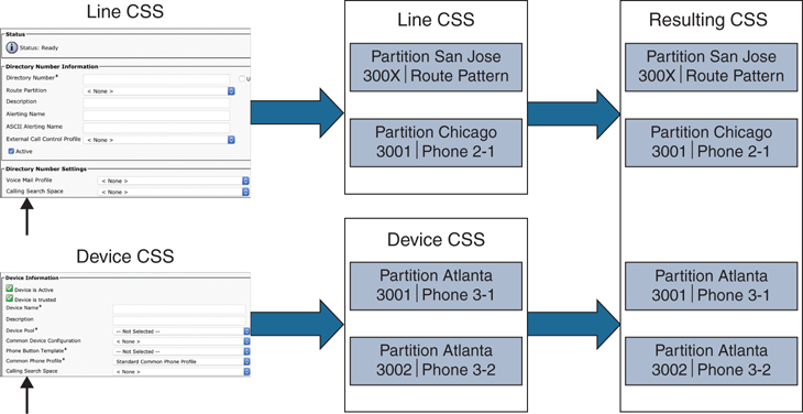
Figure 18-7 Line CSS and Device CSS Order on a Single Phone
In the example from Figure 18-7, the line CSS of the calling phone includes the San Jose and Chicago partitions, and the device CSS of the calling phone includes the Atlanta partition. Route pattern 300X is in the San Jose partition, directory number 3001 is used at Phone 2-1 in the Chicago partition, and the same directory number 3001 is used at Phone 3-1 in the Atlanta partition. If the calling phone dials 3001, the Cisco Unified Communications Manager interprets the dialed digits and searches for the closest match.
The route pattern 300X represents 10 possible numbers and is therefore not a “closest match,” as compared to the two directory numbers of 3001. Out of the two equally matched directory numbers, the number of Phone 2-1 is used to extend the call because it is in the partition that is listed first from the line CSS. Based on this current configuration, Phone 3-1 can never be reached from the phone with these CSSs. Site codes would be needed in order to reach Phone 3-1.
The importance of this example is to illustrate that the line CSS has higher priority over the device CSS. If the line CSS and device CSS were reversed, the call would be sent to Phone 3-1. Although route pattern 300X matches the dialed number and is listed in the first partition, it is not used to route the call in this example. The first priority for the call-routing decision is the best match; the order of partitions is important only if multiple best matches exist.
A common misunderstanding is that the first matching pattern found when searching through the partitions in the order that is specified in the CSS is used for call routing, regardless of the quality of the match. If this scenario were true, subsequent partitions of the CSS would be looked at only if no match was found in the earlier partitions. However, all partitions are immediately considered for best-match logic. The partition order is relevant only if multiple best matches exist.
When you are creating partitions and CSSs, you should always create partitions first. Use the following steps to configure partitions and CSSs on the Cisco Unified Communications Manager:
Step 1. Create partitions.
From Cisco Unified Communications Manager Administration, navigate to Call Routing > Class of Control > Partition.
Click Add New and enter a name for the partition.
Note
To enter multiple partitions, use one line for each partition entry. You can enter up to 75 partitions; the names and descriptions can have up to a total of 1475 characters. The partition name cannot exceed 50 characters. Use a comma (,) to separate the partition name and description on each line. If a description is not entered, Cisco Unified Communications Manager uses the partition name as the description.
Click Save when finished.
Once partitions have been created, they can be assigned to dialable patterns such as directory numbers, route patterns, or translation patterns.
Step 2. Create CSSs.
Navigate to Call Routing > Class of Control > Calling Search Space.
Choose one of the following options:
Note
Several CSSs exist by default in the Cisco Unified Communications Manager. After partitions have been configured, the administrator may choose to modify an existing CSS or create new ones.
Click Add New to add a new calling search space.
Click Find and select an existing CSS.
From the Calling Search Space Configuration page, enter a Name and optionally a Description for the CSS.
From the Available Partitions box, select the partitions to be added to this CSS, and then click the down arrow. These partitions will be searched based on the order they are listed. Use the up- and down-arrow keys to the right of the Selected Partitions box to change the order of any selected partition.
Click Save once the CSS has been configured.
Once all the CSSs have been configured, assign the appropriate CSS to entities that can request lookups to the call-routing table to route a call. Examples of such entities are phones and phone lines, trunks, gateways, and translation patterns.
A translation pattern can support both a partition as a called entity and a CSS as the calling entity. The translation pattern is a dialable pattern in the call-routing table as the target of a call-routing request. If matched, the pattern invokes a new call-routing request for the translated pattern. The partition at the translation pattern specifies who can match the pattern. The partition is required in the CSS of the calling device. The CSS at the translation pattern specifies the entries of the call-routing table that the translation pattern can see for its call-routing request when trying to find the translated pattern in the call-routing table.
Time of Day (ToD) Routing
Time of day (ToD) routing is a practical means of controlling when calls across a PSTN are allowed, in addition to who is allowed to place those calls. For example, a company noticed its phone bill increased significantly during recent months. Upon closer investigation, the staff realized that multiple international calls were being placed after closing hours during the week. That company had recently contracted a new cleaning company to come in after hours to clean the office. The cleaning personnel were making international calls during their shifts. The Collaboration administrators were able to resolve this issue and prevent after-hours calls from being made by simply introducing ToD routing to the existing network.
You can use ToD routing to define time periods. You can define a start time and an end time, and also specify repetition intervals either as days of the week or a specified date on the yearly calendar. The following steps outline how to configure ToD routing in the Cisco Unified Communications Manager:
Step 1. Configure a time period.
From Cisco Unified Communications Manager Administration, navigate to Call Routing > Class of Control > Time Period.
Click Add New and configure the following fields in the Time Period Configuration window:
Name: Enter a name for the time period.
Time of Day Start: Choose a start time from the drop-down menu.
Time of Day End: Choose an end time from the drop-down menu.
Repeat Every: Optionally choose a start and end date based on weeks or years.
Click Save.
Step 2. Configure a time schedule. The time periods that were configured in the preceding step are building blocks for this schedule. Time periods can be assigned to multiple schedules.
Navigate to Call Routing > Class of Control > Time Schedule.
Click Add New and enter a Name for the new time schedule.
Click Save.
In the Time Schedule Configuration window, the Time Period Information box will appear. Select the time periods that should be added to this time schedule from the Available Time Periods box and use the down-arrow key to move them to the Selected Time Periods box. This is an ordered list from top down, so the order can be changed using the up- and down-arrow keys to the right of the box.
Click Save.
Step 3. Associate time schedules with partitions to determine where calling devices search when they are attempting to complete a call during a particular time of day.
Navigate to Call Routing > Class of Control > Partition.
Click Find, and select a partition to modify from the list.
From the Partition Configuration page, use the Time Schedule drop-down list to choose a time schedule to associate with this partition. The time schedule specifies when the partition is available to receive incoming calls. If you choose <None>, the partition remains active at all times.
Click Save.
Location-Based CAC Bandwidth Requirements
An enterprise network uses bandwidth for many different purposes, and all IP-based communication usually crosses the same network edge. You could have voice and video traffic crossing the WAN, while large files are being transferred to an FTP server at a remote location, while other devices are accessing email or other services in the cloud. The result is that each device is competing for bandwidth across the company’s network. Individual sites of a multisite deployment are usually interconnected by an IP WAN. Bandwidth on WAN links is limited and relatively expensive. Therefore, the goal is to use the available bandwidth as efficiently as possible. You should discourage unnecessary traffic, such as social media sites and personal use, and consider implementing methods for bandwidth optimization. Figure 18-8 illustrates the dichotomy of an unmanaged enterprise network across a WAN.

Figure 18-8 Network Issues Across a WAN
Implementing QoS policies will certainly help during high congestion times across the network, but QoS will not prevent overutilization of bandwidth. Imagine a scenario where a corporate WAN can handle up to 1 Mbps total bandwidth. If two endpoints place an audio-only call using the G.711 codec for audio, they will consume 87.2 kbps: 64 kb are for the payload, and 23.2 kb are for headers. That means that this WAN link can support up to roughly 11 audio-only calls, assuming there is no other network traffic consuming bandwidth at the time of the calls. Now imagine what happens when the eleventh call attempt is placed. The call isn’t dropped. Rather, this call leg will begin barrowing bandwidth from the other existing calls, and everyone will suffer quality loss during their calls, even if proper QoS has been implemented. This is where Call Admission Control (CAC) comes into the picture.
Cisco has several Call Admission Control mechanisms that can be implemented to control how bandwidth is used across your network. Using CAC in the Cisco Unified Communications Manager allows administrators to control the codec used on a per-call basis depending on the sites between which calls are placed, as well as the overall bandwidth used when calls are placed across the WAN.
Regions are the first settings on the Cisco Unified Communications Manager that an administrator should configure for Call Admission Control. Regions, which were discussed in previous chapters, control the codecs used between endpoints when calls are set up. There is a specific bandwidth allocation associated with each audio codec, so you can easily plan and predict how much bandwidth is going to be consumed. G.711 is an uncompressed codec and consumes 87.2 kbps per call with average audio quality. G.729 is a compressed audio codec that consumes only 31.2 kbps but suffers from poorer quality. Other codecs can be compressed or uncompressed and will have varying levels of quality accordingly.
Compression involves utilizing encoding algorithms to reduce the size of digital data. Compressed data must also be decompressed before it can be used. This extra processing imposes computational or other costs into the transmission hardware. Lossless and lossy are descriptive terms used to describe whether or not the data in question can be recovered exactly bit-for-bit when the file is uncompressed or whether the data will be reduced by permanently altering or eliminating certain bits, especially redundant bits. Lossless compression searches content for statistically redundant information that can be represented in a compressed state without losing any original information. By contrast, lossy compression searches for nonessential content that can be deleted to conserve storage space.
By contrast to audio, video is very greedy and bursty when it comes to bandwidth consumption. Video codecs do not have a specific set bandwidth rate to them like audio codecs. You can place a video call using 480p30 resolution at 384 kbps or at 2 Mbps. However, using a higher codec can provided better efficiency and thus consume less bandwidth. Therefore, when you are configuring regions in the CUCM, you do not select a codec specifically; rather, you set the per-call bandwidth rate that is allowed between each site. There are two fields to configure video bit rates in the Regions settings page. The Video Calls column has to do with UC endpoints that can place video calls, such as 8845 and 8865 IP video phones and the Cisco Jabber client. The Immersive Video Calls column has to do with any Cisco Telepresence video endpoint, such as the DX80, MX700, SX80, or Webex endpoints.
Whereas regions deal more with a per-call bandwidth, locations control total bandwidth consumption. The following three locations are predefined in the Cisco Unified Communications Manager:
Hub_None: This is a sample location that typically serves as a hub linking two or more locations. It is configured by default with the Unlimited intra-location bandwidth allocations for audio, video, and immersive bandwidth, but you can specify bandwidth allocations for each of these. By default, devices not assigned to other locations are assigned to Hub_None automatically.
Phantom: This location specifies unlimited bandwidth for audio, video, and immersive calls. Specify this location to allow successful Call Admission Control for calls across inter-cluster trunks that use the H.323 or SIP trunks to certain destinations that support the earlier location CAC feature.
Shadow: This is a system location created for inter-cluster enhanced location CAC. To pass locations across clusters, the SIP inter-cluster trunk (ICT) must be assigned to the Shadow system location.
An administrator can create custom locations as well. When setting up locations, remember that the bandwidth rate is total bandwidth, not per call. Also, overhead is not calculated automatically, so you will have to include overhead when setting the bandwidth limitations. For video calls, add 20 percent to each call rate and then multiply by the number of calls allowed. If the call rate is 384 kb, add 20 percent to give a total of 460 kbps. If you wanted to support 10 calls, then 460 × 10 = 4600 kbps.
Use the following steps to configure location-based CAC on the Cisco Unified Communications Manager. Figure 18-9 illustrates the Location Configuration window.

Figure 18-9 Location Configuration Window on CUCM
Step 1. Configure locations on the Cisco Unified Communications Manager.
From Cisco Unified Communications Manager Administration, navigate to System > Location Info > Location.
Click Add New and enter the following information in the Location Configuration window.
Name: Enter a name for the location.
Location: Select a location from the list.
Weight: Enter the relative priority of this link in forming the effective path between any pair of locations. The effective path has the least cumulative weight of all possible paths. Valid values are 0–100.
Audio Bandwidth: Enter the maximum amount of audio bandwidth in kbps that is available for all audio calls on the link between this location and other locations. For audio calls, the audio bandwidth includes overhead.
Video Bandwidth: Enter the maximum amount of video bandwidth in kbps that is available for all video calls on the link between this location and other locations. For video calls, the video bandwidth does not include overhead.
Immersive Video: Enter the maximum amount of immersive video bandwidth in kbps that is available for all immersive video calls on the link within this location. For video calls, the immersive video bandwidth does not include overhead.
Click Save when finished.
Locations can be assigned to phones directly, or they can be added to device pools, which is the recommended method. Each phone is automatically assigned the Hub_None location. However, location settings in the device pool override location settings on the phone.
Step 2. Assign locations to device pools.
Navigate to System > Device Pool.
Choose one of the following options:
Click Add New to add a new device pool.
Click Find and choose a device pool from the resulting list to modify the settings for an existing device pool.
On the Device Pool Configuration page, under the Roaming Sensitive Settings section, locate the Locations menu option and use the drop-down list to select the appropriate location.
Click Save. If an existing device pool has been modified, click the Apply Config button so that the changes will be pushed to any phones already configured with this device pool.
Call Coverage
Call coverage is part of the dial plan and ensures that all incoming calls are answered. The following call coverage features are typically implemented for individuals:
Call Forward: If the called phone does not answer the call, the call should be forwarded to another phone or voicemail. Call forward options include Call Forward Busy (CFB) internal and external, Call Forward No Answer (CFNA) internal and external, Call Forward No Coverage (CFNC) internal and external, plus several others.
Shared Lines: A shared line is a directory number that is assigned to more than one device within the same partition, allowing the call to be accepted on more than one phone.
Call Pickup: Call pickup allows a call that is ringing on a phone to be picked up at another phone.
Call hunting is another complex and flexible feature that provides call coverage. Call hunting is based on a pilot number that, if called directly or used as a call forward target, allows hunting through multiple line groups. Several hunting algorithms exist, ranging from a round-robin selection of group members to a broadcast option that rings all members of a line group.
Call queuing allows hunt pilot callers to be held in a queue while they wait for an agent to become available. It enables customers to provide a professional call coverage solution without the need to deploy a Cisco Unified Contact Center product if the rich features of a contact center solution are not required.
Hunting
The Cisco Unified Communications Manager call hunting implementation is composed of four main components. They are hunt pilots, hunt lists, line groups, and line group members. A user can dial a hunt pilot number, which will direct the call to a hunt list, that in turn selects a line group, which contains a prioritized list of line group members. Though this is the order of operation for hunting in the Cisco Unified Communications Manager, the order of configuration for each of these components must be in the reverse order. Figure 18-10 illustrates the order of operation for hunting on the Cisco Unified Communications Manager.
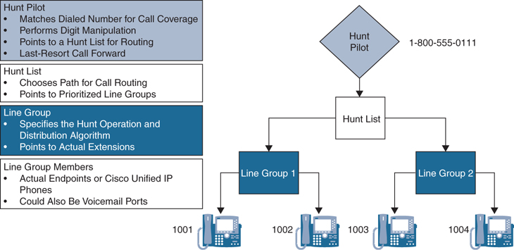
Figure 18-10 CUCM Hunting Order of Operation
Line Group Members
A line group member could be the directory numbers or voicemail ports assigned to line groups. Line group members are the Cisco Unified IP phones or Cisco Telepresence endpoints that a line group can access. These endpoints can be numbers or voicemail ports. CTI ports and CTI route points cannot be added to a line group. Therefore, calls cannot be distributed to endpoints that are controlled through CTI applications. Obviously, endpoints must be configured in, and preferably registered to, the Cisco Unified Communications Manager before they can be added to a line group.
Hunt Lists
A hunt list is an ordered list of line groups that are used for call coverage. Hunt lists have the following characteristics:
Multiple hunt pilots can point to the same hunt list.
Multiple hunt lists can contain the same line group.
A hunt list is a prioritized list of line groups; line groups are hunted in the order of their configuration in the hunt list.
A hunt list does not perform digit manipulation.
Hunt lists are assigned to hunt pilots. Figure 18-11 illustrates the configuration menus for hunt lists on the Cisco Unified Communications Manager.
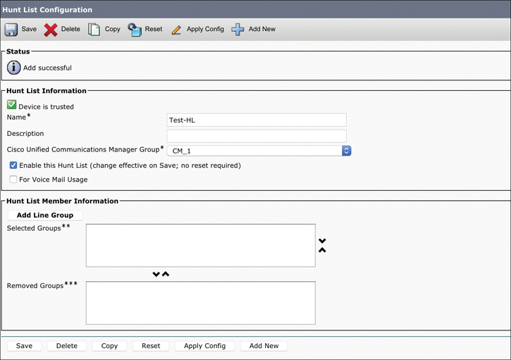
Figure 18-11 Configuration Options for Hunt Lists on the CUCM
Line Groups
Line groups are assigned to hunt lists and are composed of a list of line group members. A hunt list can have one or more line groups. At the line group, hunt options and distribution algorithms can be specified to define how call hunting should be performed for the members of a line group. Line groups control the order in which a call is distributed, and they have these characteristics:
The RNA Reversion Timeout specifies how long the hunting algorithm rings a member of the line group before proceeding to hunt according to the Line Group No Answer hunt option setting.
Line groups are configured with hunt options, which describe how hunting should be continued after trying the first member of the line group. The hunt options are configured based on per-hunt failure events, such as No Answer, Busy, or Not Available.
Line groups are configured with a global distribution algorithm, which is used to select the next line group member for hunting. The algorithm options include the following:
Try Next Member; Then Try Next Group in Hunt List
Try Next Member, but Do Not Go to Next Group
Skip Remaining Members, and Go Directly to Next Group
Stop Hunting
Line groups point to specific extensions, which are typically IP phone extensions or voicemail ports.
The same extension may be present in multiple line groups.
Figure 18-12 shows the configuration options for line groups.
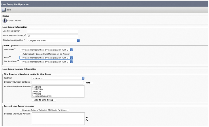
Figure 18-12 Configuration Options for Line Groups on the CUCM
Hunt Pilots
Hunt pilots are dialable patterns, such as route patterns and directory numbers, in the call-routing table. The hunt pilot points directly to a hunt list. Hunt lists point to line groups, which point to endpoints. A hunt pilot can be called directly, such as to provide a certain service to customers. Alternatively, an IP phone can be configured to forward unanswered or busy call attempts that it receives to the hunt pilot to provide call coverage.
If the directory number of the phone is dialed directly and the call is busy or not answered, the forwarding configuration of the line (CFB or CFNA setting) can forward the call to a hunt pilot. However, while hunting, the forwarding configuration of line group members is ignored. If the hunting algorithm rings a phone and the call is not answered, the CFNA setting of that phone is ignored. The hunting algorithm goes on to the next line group member.
At the hunt list, digit manipulation can be configured to transform the calling and called number before the call is passed on to line group members. Calls can also be redirected to a final destination when the hunting fails because of one or both of these reasons:
All hunting options have been exhausted and the call still is not answered.
A maximum hunt timer that is configured at the hunt list has expired.
This call redirection is configured in the Hunt Call Treatment Settings section of the Hunt Pilot Configuration page, and the destination for this redirect can be either of these options:
Forward Unanswered Calls to Destination or Forward Busy Calls to Destination: A specific destination that is configured globally at the hunt pilot.
User Forward Settings of Line Group Member: A personal preference that is configured at the phone line of the originally called number, when hunting on behalf of that number fails. The personal preference is configured by using the Call Forward No Coverage (CFNC) settings at the phone line.
You can implement the personal preferences option. To do so, configure a user phone so that the Forward No Answer field redirects the call to a hunt pilot, which searches for someone else to answer the call. If call hunting fails because all the hunting options are exhausted or because a timeout period expires, the call can be sent to a personalized destination for the person who was originally called. For example, if you set the Forward No Coverage field in the Directory Number Configuration page to a voicemail number, the call will be sent to the voice mailbox of that person if hunting fails.
These considerations apply to calls that are processed by hunt pilots:
Call Pickup and Group Call Pickup are not supported on calls that a hunt pilot distributes. A member of the line group cannot pick up a hunt pilot call that is offered to another member in the line group, even if both members belong to the same Call Pickup group.
The hunt pilot can distribute calls to any of its line group members, regardless of the calling privileges implementation of the line group members. If line group members are configured with a partition, the hunt pilot overcomes all partitions and CSS restrictions.
Call Hunting Operation and Call Flow
Now that you have a basic understanding of the components involved with call hunting, a description of the call hunting operation is in order. The call hunting flow in the Cisco Unified Communications Manager call hunting configuration is as follows:
Either a direct call is placed to the hunt pilot number, or a call is forwarded from a phone to the hunt pilot number.
The hunt pilot that is configured with the appropriate hunt pilot number starts the maximum hunt timer to monitor the overall hunting time. If the timer expires, hunting stops. The hunt pilot is associated with a hunt list.
The hunt list that is associated with the hunt pilot sends the call to the first line group that is configured in the hunt list.
The line group sends the call to the first line group member, based on the distribution algorithm that is configured for the line group. The possible distribution methods are as follows:
Top down
Circular
Longest idle time
Broadcast
If the line group member (or members, in case of broadcast) that the distribution algorithm selects does not answer the call, the hunt option specifies how hunting should continue. The hunt option is configured independently, per hunt failure reason, for the line group. Possible hunt failure reasons are No Answer, Busy, and Not Available. In hunt failures that result in No Answer, assumedly the RNAR timer that is configured for the line group has expired.
If the hunt option that is configured for the appropriate hunt failure reason is Stop Hunting, hunting stops.
If the hunt option that is configured for the appropriate hunt failure reason is Skip Remaining Members and Go Directly to Next Group, and there are no more line groups, hunting stops. If there are additional line groups, the process continues with the next line group (step 4).
If the hunt option that is configured for the appropriate hunt failure reason is Try Next Member Then Try Next Group in Hunt List, and there are additional line group members, the process continues with the next line group member (step 4). If there are no additional line group members, the next line group is used. If there are additional line groups, the process continues with the next line group (step 4). If there are no more line groups, hunting stops.
When hunting stops, the following are possible reasons:
Stop Hunting is the hunt option that was applied after a call was not accepted by the last attempted line group member.
After hunting tried the last line group member, there were no other line group members or other line groups to be used. This reason is known as hunt exhaustion.
The maximum hunt timer that is configured for the hunt pilot expired.
Once the process has exhausted all hunting options, the hunt pilot continues with the following actions.
Review the hunt pilot configuration for its final forwarding settings. If the hunt pilot is not configured for final forwarding, the call fails and a reorder tone is played.
Review the final forwarding destination settings that are configured for the hunt pilot:
If a Final Forwarding number is specified for the hunt pilot, route the call to the specified number.
If Use Personal Preference is selected, route the call to the number that is configured for CFNC on the phone line that invoked the call to the pilot number.
Figure 18-13 illustrates the call hunting flow on the Cisco Unified Communications Manager.

Figure 18-13 Call Hunting Flow
Call Queuing Settings
Call queuing allows hunt pilot callers to be held in a queue while they wait for an agent to become available. Call queuing is based on the existing call distribution capabilities that are provided by hunt lists and hunt pilots. It enables calls to a hunt pilot to be redirected to a queue if all agents that are associated with the hunt pilot are busy, logged out, unregistered, or do not answer. In call queuing, a line group member may be referred to as an agent. However, call queuing does not support an agent desktop application, routing based on agent skills, or similar contact center features. Agents can be part of multiple hunt pilots in which queuing is enabled. When an agent does not answer an offered call, the agent is automatically logged out of the hunt group. This action also applies to shared line appearances. The auto-logout occurs after expiration of the RNAR timer. An agent becomes idle after logging in to a hunt group or after finishing a call. When an agent becomes idle, the following process occurs:
The Cisco Unified Communications Manager checks all queues to which the agent is currently subscribed for waiting callers.
Out of these queued callers, the caller that has been waiting the longest is routed to the agent.
Call queuing supports announcements while calls are queued. The Cisco Unified Communications Manager has preinstalled announcements in U.S. English, but custom announcements can be uploaded. Uploading custom announcements is similar to uploading custom Music On Hold (MOH) audio files. Announcements are configured at the MOH Audio Source configuration page. The announcement to be played is chosen by referring to an MOH audio source at the Hunt Pilot Configuration page. Two different announcement types are available through the Cisco Unified Communications Manager:
Initial announcement: This announcement is played once at the beginning of the call. It can be configured to be played before or after the call is queued.
Periodic announcement: This announcement is played at a configurable interval while the call is held in the queue.
You can configure an agent phone with the Queue Status IP phone feature button. If pressed, this feature button provides information about the hunt pilot number, the number of queued calls, and the longest waiting time. For call queuing to work over SIP trunks, PRACK must be enabled on the SIP trunk.
The actual hunting process can stop because of hunt exhaustion, expiration of the hunt list maximum hunt timer, or because of running into a configured stop-hunting condition. Queuing can be enabled as another option for call management after the Cisco Unified Communications Manager stops hunting. The other two previously existing options—attempt final forwarding to a configured number or disconnect the call—are still configurable, but they are mutually exclusive. In other words, only one option can be chosen per hunt pilot. Figure 18-14 illustrates the call queuing process on the Cisco Unified Communications Manager.

Figure 18-14 Call Queuing Process
When a caller is to be placed into a queue, the Cisco Unified Communications Manager first checks whether any hunt members are logged in or registered. If no hunt members are logged in or registered, the caller is not put into the queue of the called hunt pilot. Then the Cisco Unified Communications Manager checks whether the queue of the hunt pilot is already full. The Maximum Number of Callers Allowed in Queue hunt pilot configuration setting is used to decide whether the new caller can be added to the queue. If both checks are passed successfully, the caller is added to the queue. A timer is started to monitor the time that this caller spends in the queue. If the queued call cannot be delivered to an agent before expiration of the configured Maximum Wait Time in Queue, the call is removed from the queue at expiration of the timer.
If a call is not queued at all or is removed from the queue, a final call management option must be configured. A call is not queued if there are no logged-in or registered agents or if the maximum number of queued calls is reached. A call is removed from the queue at the expiration of the maximum wait timer. The default is to disconnect the call. This setting can be changed independently according to the individual scenario by specifying a secondary destination to which the call should be routed. This secondary destination is similar to the final forwarding configuration at the hunt pilot when call queuing is not enabled. A secondary destination can be a directory number, a voicemail number, a shared line, or another hunt pilot that may or may not have queuing enabled. Be aware that sending the call to another queuing-enabled hunt pilot can result in long queuing times. This situation is especially important when cascading multiple hunt pilots.
The Maximum Number of Callers Allowed in Queue parameter is configurable from 1 to 100, and the default is 32. The Maximum Wait Time in Queue parameter is configurable from 0 to 3600 seconds, and the default for this setting is 900. Each value is configurable per hunt pilot. Call queuing supports the playing of announcements once at the beginning of a call and periodically while a call is held in a queue. Figure 18-15 illustrates the configuration procedures for hunt call treatment and queuing settings.
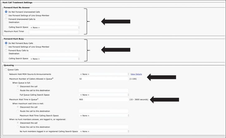
Figure 18-15 Hunt Call Treatment and Queuing Configuration Settings
Exam Preparation Tasks
As mentioned in the section “How to Use This Book” in the Introduction, you have a couple of choices for exam preparation: the exercises here, Chapter 32, “Final Preparation,” and the exam simulation questions in the Pearson Test Prep Software Online.
Review All Key Topics
Review the most important topics in this chapter, noted with the Key Topics icon in the outer margin of the page. Table 18-5 lists a reference of these key topics and the page numbers on which each is found.
Table 18-5 Key Topics for Chapter 18
Key Topic Element |
Description |
Page Number |
|---|---|---|
Paragraph |
NANP E.164 Address Patterns |
416 |
List |
Components of a Dial Plan |
416 |
Comparison of Dial Plan Configuration Elements |
419 |
|
List |
Two Ways to Address Internal Endpoints for PSTN Mapping |
419 |
Directory URI Characters Supported |
421 |
|
Paragraph |
Configuring Directory URIs in the CUCM |
422 |
PSTN Calling Privilege Class Map |
424 |
|
Paragraph |
None Partition and CSS |
424 |
List |
Call-Routing Order with COS |
427 |
Steps |
Steps to Configuring ToD Settings |
429 |
List |
Call Coverage Features for Individuals |
434 |
List |
Characteristics of Line Groups on CUCM |
436 |
List |
Designation for the Redirect of Hunt Call Treatment Settings |
437 |
List |
Hunt Distribution Methods |
438 |
List |
Announcement Types for Call Queuing |
440 |
Define Key Terms
Define the following key terms from this chapter and check your answers in the glossary:
Q&A
The answers to these questions appear in Appendix A. For more practice with exam format questions, use the Pearson Test Prep Software Online.