
Chapter 13
Layer 2 and Layer 3 QoS Parameters
This chapter covers the following topics:
QoS-Related Issues: This topic will discuss latency, jitter delay, and bandwidth issues that can be overcome with a good QoS solution.
Class Models for Provisioning QoS: This topic will discuss three different models for classifying network traffic using QoS: the 4/5 class model, 8 class model, and the 11 class model. All three are based on the QoS Baseline model.
QoS Requirements: This topic will begin to explain the layered components that make up a complete QoS solution, such as Layer 2 trust boundaries; congestion management tools; congestion avoidance tools; and policing, shaping, and link efficiency methods.
Traffic Classifications: This topic will break down different traffic classifications within the LAN, across the WAN, and over the wireless LAN.
Configure and Verify LLQ: This topic will explain how to configure and verify an LLQ QoS deployment through configuring a class map, policy map, and service policy.
Quality of service (QoS) refers to the capability of a network to provide improved service to selected network traffic over various underlying technologies. This chapter will explain what QoS is, review different components that make up a QoS solution, and provide a basic understanding of how to configure a QoS solution on an IOS router. Topics discussed in this chapter include the following:
QoS-Related Issues:
Latency, Jitter, and Packet Loss
Bandwidth
Class Models for Provisioning QoS:
4/5 Class Model
8 Class Model
QoS Baseline Model (11 Class)
QoS Requirements:
QoS Trust Boundaries
Congestion Management
Congestion Avoidance
Policing
Shaping
Link Efficiency Methods
Traffic Classifications:
LAN and WAN Traffic Classifications
WLAN Traffic Classifications
Configure and Verify LLQ:
Class Map
Policy Map
Service Policy
This chapter covers the following objectives from the Cisco Collaboration Core Technologies v1.0 (CLCOR 350-801) exam:
1.1.h QoS
5.1 Describe problems that can lead to poor voice and video quality
5.1.a Latency
5.1.b Jitter
5.1.c Packet loss
5.1.d Bandwidth
5.2 Describe the QoS requirements for these application types (voice and video)
5.3 Describe the class models for providing QoS on a network
5.3.a 4/5 Class model
5.3.b 8 Class model
5.3.c QoS Baseline model (11 Class)
5.4 Describe the purpose and function of these DiffServ values as it pertains to collaboration
5.4.a EF
5.4.b AF41
5.4.c AF42
5.4.d CS3
5.4.e CS4
5.5 Describe QoS trust boundaries and their significance in LAN-based classification and marking
5.6 Describe and determine location-based CAC bandwidth requirements
5.7 Configure and verify LLQ (class map, policy map, service policy)
“Do I Know This Already?” Quiz
The “Do I Know This Already?” quiz allows you to assess whether you should read this entire chapter thoroughly or jump to the “Exam Preparation Tasks” section. If you are in doubt about your answers to these questions or your own assessment of your knowledge of the topics, read the entire chapter. Table 13-1 lists the major headings in this chapter and their corresponding “Do I Know This Already?” quiz questions. You can find the answers in Appendix A, “Answers to the ‘Do I Know This Already?’ Quizzes.”
Table 13-1 “Do I Know This Already?” Section-to-Question Mapping
Foundation Topics Section |
Questions |
|---|---|
QoS-Related Issues |
1–3 |
Class Models for Provisioning QoS |
4–6 |
QoS Requirements |
7–9 |
Traffic Classifications |
10–11 |
Configure and Verify LLQ |
12–14 |
Caution
The goal of self-assessment is to gauge your mastery of the topics in this chapter. If you do not know the answer to a question or are only partially sure of the answer, you should mark that question as wrong for purposes of the self-assessment. Giving yourself credit for an answer you correctly guess skews your self-assessment results and might provide you with a false sense of security.
1. Which of the following is an example of drop-insensitive data?
FTP data packets
Call setup messages
Email
Voice media during a call
2. Which of the following is described as a variable of the delay over a period of time?
Latency
Jitter
Packet loss
Slow bandwidth
3. An engineer is trying to calculate how much bandwidth is being consumed across the network for video calls. All video calls are required to consume no more than 512 kbps bandwidth per call. How much bandwidth is actually being consumed per call?
(512k + 40 + 32) × 50 pps × 8 bits/bytes = 524,800 bps or 524 kbps
512 kbps
512 × 1.2 = 614.4 or 614 kbps
512 × 2 (send and receive) = 1024 kbps
4. Which of the following classifications is part of the 4/5 class model?
Real Time
Audio
Video
Bulk Data
5. Cisco recommends that call signaling be marked with CS3 for proper QoS handling. However, older model phones do not use CS3 for call signaling. What is the other QoS marking for call signaling that may need to be accounted for?
EF
DF
AF31
AF41
6. When establishing the QoS Baseline 11 class model, how much bandwidth should be allocated for interactive video?
13%
23%
25%
33%
7. What command can be entered into a switch to enable QoS at the Layer 2 level?
mls qos
mls qos interface fastethernet 0/1
mls qos trust cos
No command is needed because QoS is enabled by default.
8. Which of the following congestion management mechanisms allows delay-sensitive data, such as voice and video, to be given preferential treatment over other traffic by letting this data be dequeued and sent first?
FIFO
PQ
CQ
WFQ
CBWFQ
LLQ
9. Which of the following is an early detection congestion avoidance mechanism that ensures high-precedence traffic has lower loss rates than other traffic during times of congestion?
CBWFQ
WRED
CAR
GTS
FRTS
10. The PHB QoS marking for voice-only packets is EF. What is the DSCP equivalent to this marking?
32
34
46
48
11. How many QoS queues do Cisco APs provide for downstream traffic being sent to wireless clients?
2
4
8
11
12. When it comes to Class-Based Weighted Fair Queuing, what advantage does LLQ offer over CBWFQ without LLQ?
LLQ provides WFQ based on defined classes for CBWFQ.
LLQ provides strict priority queueing for CBWFQ.
The weight for a packet belonging to a specific class is derived from the bandwidth assigned to the class when LLQ is used.
All packets are serviced fairly based on weight with LLQ.
13. Which of the following statements is true regarding traffic classification and traffic marking?
Traffic marking can be viewed as an additional action, specified in a policy map, to be taken on a traffic class.
Traffic classification can be viewed as an additional action, specified in a policy map, to be taken on a traffic class.
Traffic marking allows you to organize packets into traffic classes on the basis of whether the traffic matches specific criteria.
After the traffic is organized into traffic classes, traffic classification allows you to mark an attribute for the traffic belonging to that specific class.
14. You can configure class policies for as many classes as are defined on the router, up to what maximum value?
11
16
64
128
Foundation Topics
QoS-Related Issues
Quality of service (QoS) was developed out of necessity. Early networks suffered from bursty data flows due to the rate at which data came into the network. As data packets arrived on the network, they would try to consume as much bandwidth as possible. Access was on a first-come, first-served basis. The data rates available to any one user depended on the number of users accessing the network at that given time. The networking protocols that were developed prior to QoS were intentionally designed to adapt to the bursty nature of the network so that packets being sent could survive bursty traffic and brief outages within the network. The nature of how TCP packets are sent is a great example of the ingenuity behind these earlier protocols. TCP packets require an acknowledgment for each packet sent. If the acknowledgment doesn’t come within a given period of time, the TCP transmission will be resent. Email uses TCP. For this reason, an email may come into an inbox seconds after it is sent or several minutes later. The contents of the email are whole and intact, so the delivery time is irrelevant, though the arrival time of the email might be annoying. This type of traffic is referred to as drop-insensitive data because lost packets will not prevent the data from eventually transmitting.
Drop-sensitive data is negatively impacted when data packets are lost because the nature of the transmission does not allow for the packets to be resent. Drop-sensitive data is typically in real time, and the nature of UDP packets uses a one-way, one-time send delivery mechanism. It’s like a shipping company that delivers a package to your front door when you are not home to receive it. The delivery person’s job is to get the package to the door. If it is stolen before you get home, that is not the delivery company’s issue. As companies began using the packet-switched network for drop-sensitive data, such as voice and video communications, a more permanent solution had to be developed to contend with the bursty and sporadic nature of the network. Early network engineers faced with these issues would develop and support nonintegrated networks, each designed to carry a specific type of traffic. However, these network setups were very complex, not scalable, and very difficult to support.
The concept of QoS allows for various data traffic types to be carried over a single converged network, and yet each type of traffic can be treated differently. Four factors in a network design can lead to poor audio and video quality. They are bandwidth capacity, latency (delay), jitter, and packet loss. The end goal of QoS is to provide better and more predictable network services by providing dedicated bandwidth, controlled jitter and latency, and improved loss characteristics as required by the business applications. QoS achieves these goals by providing tools for managing network congestion, shaping network traffic, using expensive wide-area links more efficiently, and setting traffic policies across the network.
Latency, Jitter, and Packet Loss
Latency is the delay packets’ experience when traversing across many different network devices. Jitter is similar to latency in that it is also a delay, but jitter is a variable of the latency that occurs over a period of time. If every packet sent between phone A and phone B took the exact same amount of time to traverse the network, there would be no jitter, but there could still be a delay. When the time between when packets are delivered is different, that time variance is referred to as jitter. Jitter can be overcome with buffers, but that will add to the overall latency that occurs. Packet loss refers to packets being dropped by the router due to congestion on a link. As mentioned before, TCP packets are drop insensitive because they will be retransmitted if an acknowledgment is not received by the initiating application. By contrast, UDP packets, such as voice and video, will not be retransmitted and are therefore drop sensitive.
Bandwidth
Bandwidth capacity limitations come into play when multiple flows through the router compete for limited bandwidth. QoS is not a substitute for bandwidth, and increasing the available bandwidth will not solve all these problems either. Before bandwidth issues can be resolved, an engineer needs to calculate the bandwidth being consumed across the network. Based on the information covered earlier in this book, calculating bandwidth consumption for voice and video is relatively easy.
To calculate bandwidth requirements for voice-only traffic, an engineer must first identify the codecs being used. Other codecs may be chosen to control or limit bandwidth consumption. Although the actual codec being used is the most important parameter in this assessment, it is still very important to know about packetization and the technologies that will be used. The payload size is comparable to the header size. The more packets being sent and the shorter the packetization time, the more overhead is being consumed. If the G.711 codec, which consumes 64 kbps bandwidth, is being used with a packetization period of 20 ms, and the voice payload is 160 bytes at 50 packets per second, the bandwidth for the call is 87.2 kbps. However, this calculation does not factor in the Layer 2 or Layer 3 overhead. If we take the overhead into account, the total bandwidth being consumed will be even higher. Some QoS tools also affect overhead bandwidth, such as Compressed Real-time Transport Protocol (cRTP) and link fragmentation and interleaving (LFI), but they will be discussed later in this chapter. All packets being equal, there are definitive bit counts to the Layer 2 and Layer 3 headers. Figure 13-1 illustrates the total bandwidth calculations for a G.711 call with Layer 2 and Layer 3 overhead included.
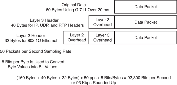
Figure 13-1 Total Bandwidth Calculations for a Call with Overhead
Calculating the bandwidth for a video call is similar to an audio call, except the math required for calculating the overhead is much simpler. First, an engineer must specify the codec being used along with the resolution of the call. These two factors together determine the bandwidth and compression of the video call. The codec alone cannot determine the bandwidth used for a video call, nor can the resolution alone. A user can place a video call at 720p30 using H.263 and will consume 1152 kbps bandwidth. The same call can be placed using the 720p30 resolution and the H.264 codec and consume only 768 kbps bandwidth. However, if the H.264 codec is used for a 480p30 call, the bandwidth required could range anywhere between 256 kbps and 512 kbps.
Another consideration when calculating bandwidth for a video call is that the total bandwidth allocated for the call is for both audio and video. If you were to place a 384 kbps call using the G.711 codec for audio and H.264 codec for video, 64 kbps would be allocated to audio, leaving 320 kbps for video. In that same call, if G.722 were used at 48 kbps, 336 kbps bandwidth would be available for video.
Once you know the total bandwidth available for the call and the codecs being used for audio and video, you can break down the Layer 2 and Layer 3 headers for audio and video separately and then add the total bandwidth back together. There is an easier way to calculate total bandwidth consumption for video calls. Simply add in 20 percent to the payload bandwidth for overhead. So, a 768 kbps call will consume approximately 922 kbps bandwidth with overhead. A 384 kbps call will consume 460 kbps bandwidth with overhead. You can do the math the long way, but you will find the actual numbers are very close to 20 percent overhead.
Once the bandwidth consumption has been calculated per call, some simple math based on actual call volume will determine the overall bandwidth consumed via voice and video communications. Determining the other limitations within a network will require other assessments of the network itself. A proper QoS design begins with a network audit and a business audit to determine the type of traffic that is running on the network and then determine the QoS requirements for the different types of traffic. Once that has been accomplished, the next step is to group the traffic into classes with similar QoS requirements. The third step occurs at the WAN Aggregation layer: to define QoS policies that will meet the QoS requirements for each traffic class.
Class Models for Provisioning QoS
Businesses should define the strategy and goals for different applications running in their network before deciding on a QoS plan or applying any QoS tools. The number of different traffic classes identified within the company’s network should directly correlate to the end-to-end QoS objectives of the business. Three different QoS strategy models can be deployed, depending on the granularity of applications running within a company’s network:
4/5 Class Model
8 Class Model
QoS Baseline Model (11 Class)
Although the more classes you define, the more specific and granular traffic treatment will be per application, the selection of a certain strategy model must be based on application requirements coupled with the WAN provider QoS model. The following sections provide a detailed view of each of these QoS strategy models.
4/5 Class Model
The 4/5 class model is the simplest of the three models in terms of QoS polices and typically accounts for real-time communications, call signaling, critical data, best-effort data, and scavenger data. The call signaling and critical data are often grouped together as a “mission-critical” category, thus this model is called the 4/5 class model. There could be four or five classes depending on how services are grouped together. The mission-critical class can also be used for multimedia conferencing, multimedia streaming, and bulk data applications. The 4/5 class model is commonly used within small and medium-sized businesses (SMB) that have deployed VoIP telephony. The five traffic classes of QoS markings and guarantees are as follows:
Real Time: Typically voice-only communications. Marked with EF and provisioned to leverage up to 33 percent of link bandwidth.
Call Signaling: Marked with CS3 and provisioned to leverage a minimum of 7 percent of link bandwidth.
Critical Data: Marked with AF31 and provisioned to leverage 35 percent of link bandwidth. When Signaling and Critical Data are combined, CS3 is used across the board.
Best Effort Data: Marked with DF and provisioned to take advantage of 25 percent of link bandwidth.
Scavenger: Marked with CS1 and provisioned to utilize any unused available link bandwidth. The Scavenger class does not have bandwidth directly provisioned, so packets marked CS1 will be sent only if bandwidth is available and will be the first packets to drop during high congestion times.
Voice and signaling guarantees must be selected based on the volume of voice calls and the VoIP codec that is used through the given link. Mission-critical data is selected based on the decision of the director of each company department who has given info about critical business application needs to the networking team. Platform-specific constraints or service-provider constraints may affect the number of classes of service. Businesses should consider a migration strategy to allow the number of classes to be smoothly expanded as future needs arise.
8 Class Model
As needs arise, businesses might need to expand their service groups to the 8 class model, which builds on the 4/5 class model by dividing three of the classes into two more granular classes each. The additions to this model include splitting the Real Time class into two distinct classes: Voice and Video. The Critical Data class is divided into Network Control and Critical Data. The explicitly defined Network Control traffic class is used for applications such as network routing protocol updates or network infrastructure control traffic such as operations, administration, and maintenance (OAM). Finally, the Best Effort class is divided into Bulk Data and Best Effort classes. The recommendations for each traffic class in this model are as follows:
Voice: Marked with EF and limited to 10 percent of link bandwidth in a strict-priority queue.
Video: Marked with AF41 or sometimes as EF and limited to 23 percent of link bandwidth in a strict-priority queue.
Call Signaling: Marked CS3 and provisioned with a minimum of 2 percent of link bandwidth.
Network Control: Marked with CS2 and provisioned with a minimum of 5 percent of link bandwidth.
Critical Data: Marked with AF31 and provisioned with 25 percent of link bandwidth.
Bulk Data: Marked with AF11 and provisioned with 10 percent of link bandwidth with WRED enabled.
Best Effort: Marked with DF and provisioned with 25 percent of link bandwidth.
Scavenger: Marked with CS1 and provisioned to utilize any unused available link bandwidth. The Scavenger class does not have bandwidth directly provisioned, so packets marked CS1 will be sent only if bandwidth is available and will be the first packets to drop during high congestion times.
Although Cisco does recommend configuring call signaling with CS3, some legacy Cisco Unified IP phone products still mark call signaling to AF31. Cisco has been working on a marking migration from AF31 to CS3 with its newer Cisco Unified IP phone models, but some businesses that use older phone models may still want to reserve both AF31 and CS3 for call signaling. In these cases, the critical data applications should be marked to a temporary placeholder nonstandard DSCP, such as 25. After companies migrate their phones to the newer IP phone models, the QoS Baseline marking recommendations of CS3 for call signaling and AF31 for critical data applications should be used.
QoS Baseline Model (11 Class)
Cisco has adopted a new initiative called the QoS Baseline. The QoS Baseline is a strategic document designed to unify QoS within Cisco, from enterprise to service provider and from engineering to marketing. The QoS Baseline was written by Cisco’s most qualified QoS experts, who have developed or contributed to the related IETF RFC standards and as such are supremely qualified to interpret these standards. The QoS Baseline also provides uniform, standards-based recommendations to help ensure that QoS designs and deployments are unified and consistent. You can see the “QoS Baseline at a Glance” document at the following link: https://www.cisco.com/en/US/technologies/tk543/tk759/technologies_white_paper0900aecd80295a9b.pdf. Several books that go into more detailed information about this model also are available.
The QoS Baseline defines up to 11 classes of traffic that might be viewed as critical to a given enterprise. The 11 class QoS Baseline model builds on the 8 class model, and represents Cisco’s interpretation of the RFC 4594 recommendation, which outlines 12 different classes of traffic. The recommendations for each traffic class in this model are as follows:
Voice: Refers to voice only, and it is marked with EF and limited to 10 percent of link bandwidth in a strict-priority queue.
Interactive Video: Refers to voice and video, and it is marked with AF41 or sometimes as EF and limited to 13 percent of link bandwidth.
Streaming Video: Marked with CS4 or sometimes as EF and limited to 10 percent of link bandwidth.
Call Signaling: Marked with CS3 and provisioned with a minimum of 2 percent of link bandwidth.
IP Routing: Marked with CS6 and limited to 3 percent of link bandwidth.
Network Management: Marked with CS2 and provisioned as guaranteed 2 percent of link bandwidth.
Mission Critical Data: Marked with AF31 and provisioned with 15 percent of link bandwidth.
Transactional Data: Marked with AF21 and provisioned with 10 percent of link bandwidth with Weighted Random Early Detection (WRED) enabled.
Bulk Data: Marked with AF11 and provisioned with 10 percent of link bandwidth with WRED enabled.
Best Effort Data: Marked with 0 and provisioned with 25 percent of link bandwidth.
Scavenger: Marked with CS1 and provisioned to utilize any unused available link bandwidth. The Scavenger class does not have bandwidth directly provisioned, so packets marked CS1 will be sent only if bandwidth is available and they will be the first packets to drop during high congestion times.
Enterprises do not need to deploy all 11 classes of the QoS Baseline model. This model is intended to be a forward-looking guide that considers as many classes of traffic with unique QoS requirements as possible. Familiarity with this model can assist in the smooth expansion of QoS policies to support additional applications as future requirements arise. However, at the time of QoS deployment, the enterprise needs to clearly define its organizational objectives, which will correspondingly determine how many traffic classes will be required.
This consideration should be tempered with the determination of how many application classes the networking administration team feels comfortable with deploying and supporting. Platform-specific constraints or service-provider constraints may also affect the number of classes of service. At this point, you should also consider a migration strategy to allow the number of classes to be smoothly expanded as future needs arise. Figure 13-2 illustrates the strategy Cisco recommends for expanding the number of classes of service over time.

Figure 13-2 Strategy for Expanding the Number of Classes of Service over Time
QoS Requirements
After a network has been assessed and a class model for provisioning QoS has been chosen, many layers to a proper QoS solution must still be deployed. As mentioned earlier in this chapter, the end goal of QoS is to provide better and more predictable network services by providing dedicated bandwidth, controlled jitter and latency, and improved loss characteristics as required by the business applications. Therefore, understanding what the voice and video QoS requirements are will help in deploying the other aspects of the QoS solution. The end goal of a properly designed voice and video network solution should be to maintain a delay of less than 150 ms, jitter less than 30 ms, and a packet loss of less than 1 percent.
The first step in designing a QoS solution is to identify and establish the QoS trust boundaries. Then you will need to set up the congestion management and the congestion avoidance. Additional tools that will need to be configured include policing and shaping. Optionally, you might want to also deploy some link efficiency methods. All of these topics will be discussed in depth in this section of the chapter. It is also important to bear in mind that QoS parameters will not be enforced until there is congestion over the network.
QoS Trust Boundaries
When it comes to QoS, it is best practice to mark packets as close to the source as possible. Most devices, such as computers and servers, cannot mark their own packets and should not be trusted even if they can. Cisco phones, however, can mark their own packets and can be trusted with the QoS markings they provide. Therefore, QoS trust boundaries should be set up so that the switch will trust the QoS markings that phones place on their own packets. Layer 2 QoS uses a mechanism called class of service (CoS), which operates on the 802.1Q VLAN. Unlike Layer 3 QoS mechanisms, CoS does not ensure network performance or guarantee priority in packets being delivered. Therefore, after packets are marked with CoS, they will need to be converted to DSCP using the cos-to-dscp map, which is built into all Cisco switches. By default, QoS on a Cisco access switch is disabled. Once enabled, the switch does not trust QoS settings from a phone. Two simple commands can be entered under the global menu on a switch to enable QoS and change the trust boundary. Once it is enabled, you can use a show command to verify these settings. Example 13-1 illustrates the QoS enable and trust boundary commands and the show verification command.
Example 13-1 QoS Enable and Trust Boundary Commands
Switch(config)# mls qos
Switch(config)# interface fastethernet 0/1
Switch(config-if)# mls qos trust cos
Switch(config-if)# end
Switch# show mls qos interface fastethernet 0/1
FastEthernet0/1
trust state: trust cos
trust mode: trust cos
cos override: dis
default COS: 0
DSCP Mutation Map: Default DSCP Mutation Map
Trust device: none
Obviously, this is the simplest design, and there are many other concerns to consider, along with many other settings that can be configured. This example is intended to provide a basic understanding of QoS at the Layer 2 level. For more information on QoS, refer to the “Enterprise QoS Solution Reference Network Design Guide” available at https://www.cisco.com/c/en/us/td/docs/solutions/Enterprise/WAN_and_MAN/QoS_SRND/QoS-SRND-Book.html.
Congestion Management
The WAN presents the greatest potential to be a bottleneck point within an enterprise network. WAN Internet speeds are usually much slower than LAN speeds; however, the network switches use hardware-based buffers, which compared to the interface speed are much smaller than those found on WAN interfaces in routers. This merely increases the potential for even short-lived traffic bursts on the LAN to cause buffer overflow and dropped packets. For these reasons, different QoS tools are available at the WAN than what exist within the LAN; however, all of these tools work together to provide an overall QoS implementation that has been carefully designed. The content that follows examines some of the key concepts to a proper QoS implementation.
Three models of QoS can be implemented in a Cisco network design:
Best Effort model: This model uses no QoS and does not guarantee that packets will be delivered. Obviously, this is not the model most companies would choose to implement.
IntServ model: This model uses RSVP to guarantee predictable behavior on the network for applications that have specific bandwidth and delay requirements.
DiffServ model: This model operates on classes that require special QoS treatment. It is the model that has been discussed up to this point and will continue to be the focus of this dialogue. QoS components used in the DiffServ model include classification, marking, congestion management, congestion avoidance, policing and shaping, and link efficiency.
Classification was discussed previously in the examination of class models. Markings were discussed briefly with class models and Layer 2 CoS marking and Layer 2 to Layer 3 conversion mapping. A detailed explanation of these markings is available later in the section titled “>Traffic Classifications.”
Congestion management mechanisms use the marking on each packet to determine in which queue to place packets. Different queues are given different treatment by the queueing algorithm that is based on the class of packets in the queue. Generally, queues with high-priority packets receive preferential treatment. The Cisco IOS software for congestion management, or queuing, includes the following queuing methods:
First-In First-Out (FIFO): Performs no prioritization of data packets on user data traffic. It entails no concept of priority or classes of traffic. When FIFO is used, ill-behaved sources can consume available bandwidth, bursty sources can cause delays in time-sensitive or important traffic, and important traffic may be dropped because less important traffic fills the queue.
Priority Queue (PQ): Guarantees strict priority in that it ensures that one type of traffic will be sent, possibly at the expense of all others. For PQ, a low-priority queue can be detrimentally affected, and, in the worst case, never allowed to send its packets if a limited amount of bandwidth is available or if the transmission rate of critical traffic is high.
Custom Queuing (CQ): Guarantees some level of service to all traffic because bandwidth can be allocated to all classes of traffic. You can define the size of the queue by determining its configured packet-count capacity, thereby controlling bandwidth access.
Weighted Fair Queuing (WFQ): Does not require configuration of access lists to determine the preferred traffic on a serial interface. Rather, the fair queue algorithm dynamically sorts traffic into messages that are part of a conversation.
Class-Based Weighted Fair Queuing (CBWFQ): Provides class bandwidth guarantee for user-defined traffic classes. It provides flow-based WFQ support for nonuser-defined traffic classes.
Low-Latency Queuing (LLQ): A congestion management mechanism developed by Cisco to bring strict priority queuing (PQ) to Class-Based Weighted Fair Queuing (CBWFQ). LLQ allows delay-sensitive data, such as voice and video, to be given preferential treatment over other traffic by letting this data be dequeued and sent first.
Congestion Avoidance
Congestion avoidance mechanisms monitor network traffic loads in an effort to anticipate and avoid congestion at common network bottlenecks. Congestion avoidance is achieved through packet dropping. Congestion avoidance mechanisms are typically implemented on output interfaces where a high-speed link feeds into a lower-speed link, such as a LAN feeding into a WAN. Weighted Random Early Detection (WRED) is an early detection congestion avoidance mechanism that ensures high-precedence traffic has lower loss rates than other traffic during times of congestion. WRED is not recommended for voice and video queues, and the network should not be designed to drop voice and video packets.
Policing
Policing is used to condition traffic before transmitting or receiving through the network. Policing controls traffic bursts by marking or dropping packets when predefined limits are reached. Policing mechanisms can drop traffic classes that have lower QoS priority markings. Policing tools include class-based policing and committed access rate (CAR). CAR services limit the input or output transmission rate on an interface or subinterface based on a flexible set of criteria.
Shaping
Shaping mechanisms are used on output interfaces to help smooth out mismatches in the network and limit transmission rates. Although these mechanisms are typically used to limit the flow from a high-speed link to a low-speed link, shaping could also be used to manage the flow of traffic at a point in the network where multiple flows are aggregated. Cisco IOS software uses two traffic-shaping tools called Generic Traffic Shaping (GTS) and Frame Relay Traffic Shaping (FRTS) to manage traffic and congestion on the network.
Link Efficiency Methods
Link efficiency methods reduce the overhead that is associated with voice and video transportation. These bandwidth-saving mechanisms, such as compression and link fragmentation and interleaving (LFI), help support large amounts of traffic over a slower link. Compression is one of the link efficiency mechanisms that work in conjunction with queuing and traffic shaping to manage existing bandwidth more efficiently and predictably. Two types of compression are available. Compression of the payload of Layer 2 frames can be implemented using the Stacker or Predictor algorithm. The other compression available is cRTP, which can compress the IP, UDP, and RTP headers down from 40 bytes to 2–4 bytes. Compression should be used only on slow WAN links because the drawback is the consumption of computational resources on a hop-by-hop basis. Another link efficiency method is link fragmentation and interleaving. Interactive traffic, such as voice and video, is susceptible to increased latency and jitter when the network processes large packets. This susceptibility increases as the traffic is queued on slower links. LFI can reduce delay and jitter on slower-speed links by breaking up large data packets and interleaving low-delay traffic packets with the resulting smaller packets. LFI is typically used on slow WAN links to ensure minimal delay for voice and video traffic. Figure 13-3 summarizes all of the QoS components needed for an efficient network deployment.
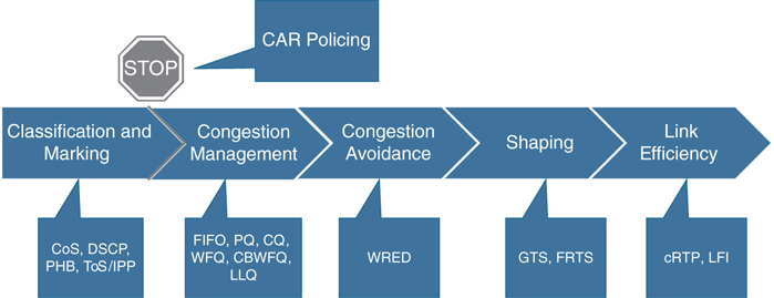
Figure 13-3 QoS Components
Traffic Classifications
QoS classification initially takes place in the Access layer; however, other QoS tools are needed to ensure voice and video quality is maintained throughout the network. In addition to traffic classification, queuing and bandwidth provisioning also ensure voice and video quality.
LAN and WAN Traffic Classifications
As mentioned previously, Layer 2 classification uses CoS markings for packets at the Access layer. The Distribution and Core layers use the existing CoS markings to map QoS to Layer 3 classifications. These Layer 3 classifications include differentiated services code point (DSCP), per hop behavior (PHB), and type of service (ToS) or IP Precedence (IPP). Table 13-2 summarizes each of these classifications and how they map to one another for different applications.
Table 13-2 Traffic Classification Map
Application |
Layer 3 Classification |
Layer 2 Classification |
||
|---|---|---|---|---|
|
ToS/IPP |
PHB |
DSCP |
CoS |
Routing |
6 |
CS6 |
48 |
6 |
Voice Only |
5 |
EF |
46 |
5 |
Voice/Video |
4 |
AF41 |
34 |
4 |
Telepresence Video |
4 |
CS4 |
32 |
4 |
Streaming Video |
3 |
CS4 |
32 |
3 |
Call Signaling |
3 |
CS3 |
24 |
3 |
Transactional Data |
2 |
AF21 |
18 |
2 |
Network Management |
2 |
CS2 |
16 |
2 |
Bulk Data |
1 |
AF11 |
10 |
1 |
Scavenger |
1 |
CS1 |
8 |
1 |
Best Effort |
0 |
0 |
0 |
0 |
In Table 13-2, voice only and voice with video traffic are separated into two different categories. The reason for this is so that when a video call is placed, both voice and video packets reach the destination at roughly the same time. There is no support for lip synchronization in SIP, so this will help preserve lip-syncing during the call. Also, when a video call is placed, the expectation is that both the voice and video media will share the same quality during the call. These reasons are why Cisco recommends deploying QoS in this manner. Notice, however, that this table is slightly different from the QoS Baseline model, although there are 11 classes in both design models. Table 13-2 provides a classification for Voice/Video and another for Telepresence Video. Cisco offers different endpoints that will utilize different QoS classifications based on type. Based on Cisco’s current endpoint portfolio, the Voice/Video applications include the 8845, 8865, and Jabber client endpoints. If you have a DX endpoint running the legacy Android software, it would fall under this category too. The Telepresence Video applications include all endpoints running CE or CTS software, including the DX, MX, SX, IX, and Webex endpoints.
After packets have been classified for Layer 2 and Layer 3, the next step is to queue traffic based on the classification. Transmit interface buffers within a campus tend to congest in small, finite intervals as a result of the bursty nature of network traffic. When this congestion occurs, any packets destined for that transmit interface are dropped. The only way to prevent dropped voice traffic is to configure multiple queues on campus switches. By enabling multiple queues on campus switches, you can configure all voice traffic to use separate queues, thus virtually eliminating the possibility of dropped voice packets when an interface buffer fills instantaneously. For this reason, Cisco recommends always using a switch that has at least two output queues on each port and the ability to send packets to these queues based on QoS Layer 2 or Layer 3 classification. The majority of Cisco Catalyst switches support two or more output queues per port.
WLAN Traffic Classifications
Just as QoS is necessary for the LAN and WAN wired network infrastructure in order to ensure high voice and video quality, QoS is also required for the wireless LAN infrastructure. Because of the bursty nature of data traffic and the fact that real-time traffic such as voice and video are sensitive to packet loss and delay, QoS tools are required to manage wireless LAN buffers; limit radio contention; and minimize packet loss, delay, and delay variation. Unlike most wired networks, however, wireless networks are a shared medium, and wireless endpoints do not have dedicated bandwidth for sending and receiving traffic. While wireless endpoints can mark traffic with 802.1p CoS, ToS, DSCP, and PHB, the shared nature of the wireless network means limited admission control and access to the network for these endpoints.
As with the wired network infrastructure, it is important to classify or mark pertinent wireless traffic as close to the edge of the network as possible. Because traffic marking is an entrance criterion for queuing schemes throughout the wired and wireless network, marking should be done at the wireless endpoint device whenever possible. Marking or classification by wireless network devices should be identical to that for wired network devices. In accordance with traffic classification guidelines for wired networks, the Cisco wireless endpoints mark voice media traffic or voice RTP traffic with DSCP 46 (or PHB EF), video media traffic or video RTP traffic with DSCP 34 (or PHB AF41), and call control signaling traffic (SCCP or SIP) with DSCP 24 (or PHB CS3). Once this traffic is marked, it can be given priority of better than best-effort treatment and queuing throughout the network. All wireless voice and video devices that are capable of marking traffic should do so in this manner. All other traffic on the wireless network should be marked as best-effort or with some intermediary classification as outlined in wired network marking guidelines. If the wireless voice or video devices are unable to do packet marking, alternate methods such as port-based marking should be implemented to provide priority to video and voice traffic.
While 802.1p and differentiated services code point (DSCP) are the standards to set priorities on wired networks, 802.11e is the standard used for wireless networks. This is commonly referred as user priority (UP), and it is important to map the UP to its appropriate DSCP value. Table 13-3 compares the 802.11e QoS values compared to wired QoS values.
Table 13-3 QoS Value Comparison with 802.11e
Traffic Type |
DSCP (PHB) |
802.1p UP |
802.11e UP |
|---|---|---|---|
Voice |
46 (EF) |
5 |
6 |
Video |
34 (AF41) |
4 |
5 |
Voice and Video Signaling |
24 (CS3) |
3 |
4 |
After traffic marking has occurred, it is necessary to enable the wired network access points (APs) and devices to provide QoS queuing so that voice and video traffic types are given separate queues to reduce the chances of this traffic being dropped or delayed as it traverses the wireless LAN. Queuing on the wireless network occurs in two directions: upstream and downstream. Upstream queuing concerns traffic traveling from the wireless endpoint up to the AP, and from the AP up to the wired network. Downstream queuing concerns traffic traveling from the wired network to the AP and down to the wireless endpoint.
For upstream queuing, devices that support Wi-Fi Multimedia (WMM) are able to take advantage of queueing mechanisms, including priority queueing. As for downstream QoS, Cisco APs currently provide up to eight queues for downstream traffic being sent to wireless clients. The entrance criterion for these queues can be based on a number of factors, including DSCP, access control lists (ACLs), and VLAN. Although eight queues are available, Cisco recommends using only two queues when deploying wireless voice. All voice media and signaling traffic should be placed in the highest-priority queue, and all other traffic should be placed in the best-effort queue. This ensures the best possible queuing treatment for voice traffic.
To set up this two-queue configuration for autonomous APs, you can create two QoS policies on the AP. Name one policy Voice and configure it with the class of service Voice < 10 ms Latency (6) as the Default Classification for all packets on the VLAN. Name the other policy Data and configure it with the class of service Best Effort (0) as the Default Classification for all packets on the VLAN. Then assign the Data policy to the incoming and outgoing radio interface for the data VLAN(s) and assign the Voice policy to the incoming and outgoing radio interfaces for the voice VLAN(s). With the QoS policies applied at the VLAN level, the AP is not forced to examine every packet coming in or going out to determine the type of queuing the packet should receive.
For lightweight APs, the WLAN controller has built-in QoS profiles that can provide the same queuing policy. Voice VLAN or voice traffic is configured to use the Platinum policy, which sets priority queueing for the voice queue. Data VLAN or data traffic is configured to use the Silver policy, which sets best-effort queuing for the Data queue. These policies are then assigned to the incoming and outgoing radio interfaces based on the VLAN. The preceding configurations ensure that all voice and video media and signaling are given priority queuing treatment in a downstream direction.
To avoid exceeding the capacity limit of a given AP channel, some form of call admission control is required. Cisco APs and wireless Unified Communications clients now use Traffic Specification (TSPEC) instead of QoS Basic Service Set (QBSS) for call admission control. Wi-Fi Multimedia Traffic Specification (WMM TSPEC) is the QoS mechanism that enables WLAN clients to provide an indication of their bandwidth and QoS requirements so that APs can react to those requirements. When a client is preparing to make a call, it sends an Add Traffic Stream (ADDTS) message to the AP with which it is associated, indicating the TSPEC. The AP can then accept or reject the ADDTS request based on whether bandwidth and priority treatment are available. If the call is rejected, the client receives a Network Busy message. If the client is roaming, the TSPEC request is embedded in the reassociation request message to the new AP as part of the association process, and the TSPEC response is embedded in the reassociation response. Alternatively, endpoints without WMM TSPEC support, but using SIP as call signaling, can be managed by the AP. Media snooping must be enabled for the Service Set Identifier (SSID). The client’s implementation of SIP must match that of the wireless LAN controller, including encryption and port numbers.
Configure and Verify LLQ
Without LLQ, CBWFQ provides WFQ based on defined classes with no strict priority queue available for real-time traffic. CBWFQ allows you to define traffic classes and then assign characteristics to that class, such as designating the minimum bandwidth delivered to the class during congestion. For CBWFQ, the weight for a packet belonging to a specific class is derived from the bandwidth you assigned to the class when you configured it. Therefore, the bandwidth assigned to the packets of a class determines the order in which packets are sent. All packets are serviced fairly based on weight; no class of packets may be granted strict priority. This scheme poses problems for voice traffic that is largely intolerant of delay, especially variation in delay. For voice traffic, variations in delay introduce irregularities of transmission manifesting as jitter in the heard conversation.
LLQ provides strict priority queueing for CBWFQ, reducing jitter in voice conversations. Strict PQ allows delay-sensitive data such as voice to be dequeued and sent before packets in other queues are dequeued. Configured by the priority command, LLQ enables use of a single, strict priority queue within CBWFQ at the class level, allowing you to direct traffic belonging to a class to the CBWFQ strict priority queue. To enqueue class traffic to the strict priority queue, you specify the named class within a policy map and then configure the priority command for the class. (Classes to which the priority command is applied are considered priority classes.) Within a policy map, you can give one or more classes priority status. When multiple classes within a single policy map are configured as priority classes, all traffic from these classes is enqueued to the same, single, strict priority queue.
One of the ways in which the strict PQ used within CBWFQ differs from its use outside CBWFQ is in the parameters it takes. Outside CBWFQ, you can use the ip rtp priority command to specify the range of UDP ports whose voice traffic flows are to be given priority service. Using the priority command, you are no longer limited to a UDP port number to stipulate priority flows because you can configure the priority status for a class within CBWFQ. Instead, all of the valid match criteria used to specify traffic for a class now apply to priority traffic. These methods of specifying traffic for a class include matching on access lists, protocols, and input interfaces. Moreover, within an access list, you can specify that traffic matches are allowed based on the IP differentiated services code point (DSCP) value that is set using the first six bits of the ToS byte in the IP header.
Although it is possible to enqueue various types of real-time traffic to the strict priority queue, Cisco strongly recommends that you direct only voice traffic to it because voice traffic is well behaved, whereas other types of real-time traffic are not. Moreover, voice traffic requires that delay be nonvariable in order to avoid jitter. Real-time traffic such as video could introduce variation in delay, thereby thwarting the steadiness of delay required for successful voice traffic transmission.
To configure network traffic marking, you use the modular quality of service (QoS) command-line interface (CLI), also referred to as MQC. The MQC is a CLI structure that allows you to complete the following tasks:
Specify the matching criteria used to define a traffic class.
Create a traffic policy (policy map). The traffic policy defines the QoS policy actions to be taken for each traffic class.
Apply the policy actions specified in the policy map to an interface, subinterface, or ATM PVC by using the service-policy command.
Figure 13-4 illustrates the process used to configure QoS within a Cisco environment.
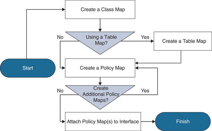
Figure 13-4 QoS Configuration Process
Class Map
Traffic classification and traffic marking are closely related and can be used together. Traffic marking can be viewed as an additional action, specified in a policy map, to be taken on a traffic class. Traffic classification allows you to organize packets into traffic classes on the basis of whether the traffic matches specific criteria. For example, all traffic with a CoS value of 2 is grouped into one class, and traffic with DSCP value of 3 is grouped into another class. The match criterion is user defined.
After the traffic is organized into traffic classes, traffic marking allows you to mark an attribute for the traffic belonging to that specific class. For instance, you may want to change the CoS value from 2 to 1, or you may want to change the DSCP value from 3 to 2. The match criteria used by traffic classification are specified by configuring a match command in a class map. The marking action taken by traffic marking is specified by configuring a set command in a policy map. These class maps and policy maps are configured using the MQC.
The following commands explain how to create a class map to define traffic classes. Within the class map, the appropriate match command is used to specify the matching criteria for the traffic classes. To create the class map and specify the matching criteria, complete the following steps:
Router> enable

Router# configure terminal

Router(Config)# class-map class-map-name
From this point, you can use a few options available within the class map to establish the search criterion against which packets are checked to determine if they belong to the class. Table 13-4 identifies four of these criteria.
Table 13-4 Four Criterion Matches for Packet Classification
MQC Command |
Description |
|---|---|
Router(config-cmap)# match access-group access-group-name |
Specifies the name of the access control list (ACL) against whose contents packets are checked to determine if they belong to the class. |
Router(config-cmap)# match input-interface interface-name |
Specifies the name of the input interface used as a match criterion against which packets are checked to determine if they belong to the class. |
Router(config-cmap)# match protocol protocol |
Specifies the name of the protocol used as a match criterion against which packets are checked to determine if they belong to the class. |
Router(config-cmap)# match fr-dlci dlci-number |
Specifies the Frame Relay DLCI number as a match criterion against which packets are checked to determine if they belong to the class. |
Policy Map
As previously mentioned, creating a table map is not required unless the desired outcome is to change some of the CoS or DSCP values. The table map contains the mapping scheme used for establishing the to-from relationship and equivalency between one traffic-marking value and another. The table map can be configured for use with multiple policy maps. The policy maps can then be configured to convert and propagate the traffic-marking values defined in the table map. Then the policy maps can be attached to the input or output interface of either the ingress or egress router, as appropriate, to serve the QoS requirements of your network. To create and configure the table map, enter the following MQC commands:
Router> enable

Router# configure terminal

Router# table-map name map from from-value to to-value
        [default default-action-or-value]
To configure a policy map and create class policies that make up the service policy, begin with the policy-map command to specify the policy map name. Then use one or more of the following commands to configure the policy for a standard class or the default class:
priority
bandwidth
queue-limit or random-detect
fair-queue (for class-default class only)
For each class that you define, you can use one or more of the commands listed to configure the class policy. For example, you might specify bandwidth for one class and both bandwidth and queue limit for another class. The default class of the policy map, commonly known as the class-default class, is the class to which traffic is directed if that traffic does not satisfy the match criteria of the other classes defined in the policy map.
You can configure class policies for as many classes as are defined on the router, up to the maximum of 64. However, the total amount of bandwidth allocated for all classes in a policy map must not exceed the minimum committed information rate (CIR) configured for the virtual circuit (VC) minus any bandwidth reserved by the frame-relay voice bandwidth and frame-relay ip rtp priority commands. If the minimum CIR is not configured, the bandwidth defaults to one-half of the CIR. If all of the bandwidth is not allocated, the remaining bandwidth is allocated proportionally among the classes on the basis of their configured bandwidth.
The following commands describe how to create and configure a policy map to use the class map and the table map. The policy map applies the appropriate QoS feature to the network traffic based on the traffic classification. To configure class policies in a policy map, use the MQC commands described in the following sections.
Router> enable

Router# configure terminal

Router(Config)# policy-map name

Router(Config-pmap)# class {class-name | class-default}

Router(Config-pmap-c)# set cos cos-value
or
Router(Config-pmap-c)# set cos dscp table name
The policy-map name command creates a policy map by the name provided and enters the policy-map configuration mode. The class command specifies the name of the class whose policy you want to create and enters policy-map class configuration mode. This class is associated with the class map created earlier. You can either enter the name of the class created earlier or enter the class-default keyword. The class-default class is used to classify traffic that does not fall into one of the defined classes. Even though the class-default class is predefined when you create the policy map, you still have to configure it. If a default class is not configured, then traffic that does not match any of the configured classes is given best-effort treatment, which means that the network will deliver the traffic if it can, without any assurance of reliability, delay prevention, or throughput. The set cos command and set cos dscp table name commands are examples of the set commands that can be used when marking traffic. Other set commands can be used as well. For a list of other set commands, refer to the “Cisco IOS Quality of Service Solutions Configuration Guide” at Cisco.com.
Other class policies can be configured here as well. To configure a class policy for a priority queue, enter the following command:
Router (config-pmap-c)# priority bandwidth in kbps
This command creates a strict priority class and specifies the amount of bandwidth in kbps to be assigned to the class.
To configure a class policy using a specified bandwidth, enter the following command:
Router (config-pmap-c)# bandwidth bandwidth in kbps
This command specifies the amount of bandwidth to be assigned to the class in kbps, or as a percentage of the available bandwidth. Bandwidth must be specified in kbps or as a percentage consistently across classes. Bandwidth of the priority queue must be specified in kbps.
To configure a class policy that specifies a number of queues, enter the following command:
Router (config-pmap-c)# fair-queue number-of-dynamic-queues
This command specifies the number of dynamic queues to be reserved for use by flow-based WFQ running on the default class. The number of dynamic queues is derived from the bandwidth of the interface.
You can create and configure as many policy maps as you need for your network. To create and configure additional policy maps, repeat the preceding commands per your network deployment plan. After all the policy maps have been created, they will need to be attached to the appropriate interface. The next section on service policy will explain how to attach the policy maps to the interfaces.
Service Policy
After you create the policy map, you must attach it to an interface. Policy maps can be attached to either the input or output direction of the interface. Depending on the needs of your network, you can attach policy maps to an interface, a subinterface, or an ATM permanent virtual circuit (PVC). To attach the policy map, enter the following commands in the MQC:
Router> enable

Router# configure terminal

Router(Config)# interface type number [name-tag]

Router(Config-if)# service-policy {input | output}
policy-map-name
This last command is the key. It attaches the specified service policy map to the output interface and enables LLQ, assuming LLQ has been configured throughout this process. Next, all these QoS settings will need to be verified.
Verify and Monitor LLQ Settings
After the QoS designs have been finalized and the proof of concept tested, it is vital to ensure that the networking team thoroughly understand the QoS features and syntax before enabling features on production networks. Such knowledge is critical for both rollout and subsequent troubleshooting of QoS-related issues. Furthermore, it is recommended to schedule network downtime in order to roll out QoS features. While QoS is required end-to-end, it does not have to be deployed end-to-end at a single instance. A pilot network-segment can be selected for an initial deployment, and pending observation, the rollout can be expanded in stages to encompass the entire enterprise. A rollback strategy is always recommended, to address unexpected issues arising from the QoS deployment.
From the Privileged Exec Mode on the router, you can use several show commands to verify that all the QoS settings have been configured correctly. Table 13-5 illustrates these show commands with a description of what information each command displays.
Table 13-5 IOS Router Show Commands for QoS
Command |
Description |
|---|---|
Router# show policy-map |
Displays all configured policy maps. |
Router# show policy-map policy-map class class-name |
Displays the configuration for the specified class of the specified policy map. Enter the policy map name and the class name. |
Router# show frame-relay pvc dlci |
Displays statistics about the PVC and the configuration of classes for the policy map on the specified data-link connection identifier (DLCI). |
Router# show policy-map interface interface-name |
When LLQ is configured, displays the configuration of classes for all policy maps. |
Router# show policy-map interface interface-name dlci |
When LLQ is configured, displays the configuration of classes for the policy map on the specified DLCI. |
Router# show policy-map interface interface-name |
Displays traffic statistics of all classes configured for all service policies on the specified interface, subinterface, or PVC on the interface. When a policy map has multiple instances of the same class, and this policy map is attached to an interface, the following command returns only the first instance: show policy-map interface interface_name output class class-name |
Exam Preparation Tasks
As mentioned in the section “How to Use This Book” in the Introduction, you have a couple of choices for exam preparation: the exercises here, Chapter 32, “Final Preparation,” and the exam simulation questions in the Pearson Test Prep Software Online.
Review All Key Topics
Review the most important topics in this chapter, noted with the Key Topics icon in the outer margin of the page. Table 13-6 lists a reference of these key topics and the page numbers on which each is found.
Table 13-6 Key Topics for Chapter 13
Key Topic Element |
Description |
Page Number |
|---|---|---|
Paragraph |
Four Factors Requiring QoS |
307 |
Section |
Latency, Jitter, and Packet Loss |
307 |
Paragraph |
Calculating Bandwidth for Voice Packets |
308 |
Paragraph |
Calculating Bandwidth for Video Calls |
309 |
List |
Three QoS Strategy Models |
309 |
List |
Five Traffic Classes of QoS Markings |
310 |
List |
Eight Traffic Classes of QoS Markings |
310 |
List |
Eleven Traffic Classes of QoS Markings |
311 |
Paragraph |
End goal of a properly designed QoS deployment for voice and video |
313 |
Paragraph |
COS and Trust Boundaries |
313 |
List |
Three models of QoS |
314 |
Traffic Classification Map |
317 |
|
Paragraph |
802.11e Explained |
318 |
QoS Value Comparison with 802.11e |
318 |
|
Paragraph |
Upstream and Downstream Queueing for Wireless Networks |
318 |
Commands |
Commands to Create a Class Map |
321 |
Four Criterion for Packet Classification |
322 |
|
Commands |
Commands to Create a Table Map |
322 |
Commands |
Commands to Configure Class Policies in a Policy Map |
323 |
Commands |
Commands to Attach a Policy Map to an Interface |
324 |
IOS Router Show Commands for QoS |
325 |
Define Key Terms
Define the following key terms from this chapter and check your answers in the glossary:
Command Reference to Check Your Memory
This section includes the most important configuration and EXEC commands covered in this chapter. It might not be necessary to memorize the complete syntax of every command, but you should be able to remember the basic keywords that are needed.
To test your memory of the commands, cover the left side of Tables 13-7 through 13-8 with a piece of paper, read the description on the right side, and then see how much of the command you can remember.
Table 13-7 Layer 2 QoS Commands
Command Syntax |
Task |
|---|---|
Switch(config)# mls qos |
Enables QoS on the Layer 2 switch and CoS to DSCP mapping. |
Switch(config-if)# mls qos trust cos |
Establishes a trust boundary between a phone and the switch for QoS. Must be enabled on the actual switchport. |
Switch# show mls qos interface fastethernet 0/1 |
Reveals that QoS has been enabled and a QoS trust boundary has been set up. |
Table 13-8 Layer 3 QoS Commands
Command Syntax |
Task |
|---|---|
Router(Config)# class-map class-map-name |
Creates a class map to be used for matching traffic to a specified class and enters class-map configuration mode. The class map name must be specified after the class-map command. |
Router(config-cmap)# match access-group access-group-name |
Specifies the name of the access control list (ACL) against whose contents packets are checked to determine if they belong to the class. |
Router(config-cmap)# match input-interface interface-name |
Specifies the name of the input interface used as a match criterion against which packets are checked to determine if they belong to the class. |
Router(config-cmap)# match protocol protocol |
Specifies the name of the protocol used as a match criterion against which packets are checked to determine if they belong to the class. |
Router(config-cmap)# match fr-dlci dlci number |
Specifies the Frame Relay DLCI number as a match criterion against which packets are checked to determine if they belong to the class. |
Router(Config)# table-map name map from from-value to to-value [default default-action-or-value] |
Creates a table map using the specified name and enters table-map configuration mode. Enter the name of the table map you want to create. Enter each value mapping on a separate line. Enter as many separate lines as needed for the values you want to map. The default keyword and default-action-or-value argument set the default value (or action) to be used if a value is not explicitly designated. |
Router(config)# policy-map name |
Specifies the name of the policy map created earlier and enters policy-map configuration mode. The policy map name must be entered with this command. |
Router(config-pmap)# class name |
Specifies the name of the class whose policy you want to create and enters policy-map class configuration mode. This class is associated with the class map created earlier. Enter the name of the class or enter the class-default keyword. |
Router(config-pmap)# class class-default name |
Specifies the default class so that you can configure or modify its policy. |
Router(config-pmap-c)# set cos cos-value |
(Optional) Sets the CoS value in the type of service (ToS) byte. |
Router(config-pmap-c)# set cos dscp table name |
(Optional) If a table map was created earlier, sets the CoS value based on the DSCP value (or action) defined in the table map. |
Router(config-pmap-c)# priority bandwidth in kbps |
Creates a strict priority class and specifies the amount of bandwidth, in kbps, to be assigned to the class. |
Router (config-pmap-c)# bandwidth bandwidth in kbps |
Specifies the amount of bandwidth to be assigned to the class, in kbps, or as a percentage of the available bandwidth. Bandwidth must be specified in kbps or as a percentage consistently across classes. Bandwidth of the priority queue must be specified in kbps. |
Router (config-pmap-c)# fair-queue number-of-dynamic-queues |
This command specifies the number of dynamic queues to be reserved for use by flow-based WFQ running on the default class. The number of dynamic queues is derived from the bandwidth of the interface. |
Router(Config-if)# service-policy {input | output} policy-map-name |
Attaches the specified service policy map to the output interface and enables LLQ. |
The 350-801 exam focuses on practical, hands-on skills that are used by a networking professional. Therefore, you should be able to identify the commands needed to configure and test QoS.
Q&A
The answers to these questions appear in Appendix A. For more practice with exam format questions, use the Pearson Test Prep Software Online.
1. Name the four factors in a network design that can lead to poor audio and video quality.
2. List the 11 classes in the QoS Baseline model.
3. The end goal of a properly designed voice and video network solution should be to maintain what parameters for delay, jitter, and packet loss?
4. Outline the QoS mapping for 802.11e User Priority to Layer 2 802.1p and Layer 3 DSCP for Voice, Video, and Signaling.
5. List all of the commands, from the switch to the router, required for a QoS deployment. Do not include optional commands.