
Chapter 12
Cisco Core Network Components
This chapter covers the following topics:
LAN, WAN, and Wireless LAN: This topic will discuss the various layers of an enterprise network to cover the LAN, WAN, and wireless LAN as they relate to collaboration.
Gateways: This topic will introduce various types of gateways, both old and new, with special emphasis on IOS gateway services through the Cisco ISR routers and the features they support that impact the Cisco collaboration solution.
The network is the most important aspect to any business today because that is what connects people together across the world. In an episode of a funny British sitcom called The IT Crowd, the IT department’s nontechnical boss was convinced that the “Internet” was a single black box. She was planning to use it as a prop in a presentation she was to present in hopes of wowing the audience. As I hope you are aware, the Internet, or any network for that matter, is not a single device. It is a combination of devices, software, and protocols that are the culmination of years of development by multiple vendors to become what it is today. It is a living entity in that it continues to grow and change as time passes, and it will continue to grow as long as people have a need for it. The vast embodiment of the Cisco core network components is too colossal to cover in one chapter. However, this chapter will introduce many concepts concerning the Cisco core network components as they pertain to collaboration. Topics discussed in this chapter include the following:
LAN, WAN, and Wireless LAN
LAN (Access Layer, Distribution Layer, Core Layer)
WAN Aggregation Design
Wireless LAN (Basic Configuration and Design, High Availability, Capacity Planning, Design Considerations)
Gateways
ISR, ASR, and IOS Software Comparisons
ISR Products Explained
This chapter covers the following objectives from the Cisco Collaboration Core Technologies v1.0 (CLCOR 350-801) exam:
1.3 Configure these network components to support Cisco Collaboration solutions
“Do I Know This Already?” Quiz
The “Do I Know This Already?” quiz allows you to assess whether you should read this entire chapter thoroughly or jump to the “Exam Preparation Tasks” section. If you are in doubt about your answers to these questions or your own assessment of your knowledge of the topics, read the entire chapter. Table 12-1 lists the major headings in this chapter and their corresponding “Do I Know This Already?” quiz questions. You can find the answers in Appendix A, “Answers to the ‘Do I Know This Already?’ Quizzes.”
Table 12-1 “Do I Know This Already?” Section-to-Question Mapping
Foundation Topics Section |
Questions |
|---|---|
LAN, WAN, and Wireless LAN |
1–6 |
IOS Gateways |
7–10 |
Caution
The goal of self-assessment is to gauge your mastery of the topics in this chapter. If you do not know the answer to a question or are only partially sure of the answer, you should mark that question as wrong for purposes of the self-assessment. Giving yourself credit for an answer you correctly guess skews your self-assessment results and might provide you with a false sense of security.
1. Which of the following is an element configured on a Layer 2 switch?
VLAN
QoS Policing
EIGRP
OSPF
2. Which of the following does the IEEE 802.1d standard define?
Layer 2 QoS
Spanning Tree Protocol
Rapid Spanning Tree Protocol
Multiple Instance Spanning Tree Protocol
3. Which of the following protocols protects data traffic from a failed router or circuit, while also allowing packet load sharing between a group of redundant routers?
HSRP
ARP
VRRP
GLBP
4. Which of the following is a “best effort” bandwidth option for network connections?
DSL
ATM
Leased Lines
Frame Relay
5. Which of the following is the wireless router to which a device would connect for network access?
WLC
LAN
LWAP
LWAPP
6. What is the recommended cell boundary overlap to provide high availability in a wireless network?
There should not be any cell boundary overlap.
20 percent
50 percent
100 percent
7. Which of the following is an analog station gateway?
E&M
FXO
PRI
FXS
8. Which of the following routers supports the IOS XE software?
ISRv
ISR 800 Series
ISR 2900 Series
ASR 9000 Series
9. Which of the following Cisco routers should an engineer choose for a customer who needs to support 1000 users at a specific location?
ISR 800 Series
ISR 1000 Series
ISR 2900 Series
ISR 4000 Series
10. Which Cisco router should be used for machine-to-machine and device-to-device deployments such as ATMs, point-of-sale kiosks, and vending machines (fixed platform)?
ISR 800M
ISR 810
ISR 860
ISR 890
Foundation Topics
LAN, WAN, and Wireless LAN
The most foundational components of any corporate communication solution are the network infrastructure components. One of the reasons Cisco is the leader in the collaboration market is that only Cisco can offer an end-to-end solution to its customers. Of course, providing superior collaboration products with extensive capabilities and beautiful designs helps contribute to the company’s ability to hold that leading position. The purpose of this chapter is not to provide an extensive education on these network components and how to configure them. However, there is such a close dependency on Cisco collaboration products and the network that it is essential to have an understanding of the network to a certain level. To provide a deeper understanding of basic networking components, Cisco offers the CCNP Enterprise certification courses, which can also be studied using the Cisco Press material. These courses and the material will provide a more thorough understanding of what each network component is and how to configure it. For the purposes of this book, we will examine the foundational network infrastructure components because they relate directly to the Cisco preferred architecture for enterprise collaboration.
A network can be defined as a group or system of interconnected things. A local-area network (LAN) is a network of devices within a limited area. This could be a business office, school, or campus. A home network is a LAN that might interconnect computers, smartphones, tablets, smart TVs, printers, and other media devices. A wide-area network (WAN) is a network of devices within a wider area than the LAN. Imagine two LAN offices, one located in New York City and the other in Washington DC, but devices within each of these locations can communicate with one another as if they were within the same LAN. This is a WAN. Then there is the wireless local-area network (WLAN) or wireless LAN. Because different technologies exist within wireless technology as compared to a physical LAN, this type of network must be categorized independently. Most home networks use some sort of consumer wireless router, but the technology behind a commercial wireless LAN goes far beyond what is available to the everyday consumer.
Now that we’ve defined the different types of networks, let’s examine some of the physical network components and how they might be used. The only network component needed to set up a LAN is a switch. A basic switch is a device with multiple physical ports to which multiple devices can be connected using an Ethernet cable so that communication between these devices can be established. Switches operate on Layer 2 of the OSI model. Cisco switches have a higher level of intelligence than a basic switch, so a network administrator can configure parameters that control how traffic flows through these switches. In fact, some of the switch models that Cisco offers can be configured with Layer 2 and Layer 3 capabilities. As switches pertain to collaboration, several configuration elements can be configured, including virtual LANs (VLANs), Cisco Discovery Protocol (CDP), Link Layer Discovery Protocol-Media Endpoint Discovery (LLDP-MED), and quality of service (QoS), to name a few. As essential as a switch is within a network, you cannot access the public Internet or establish a WAN without the next network component—the router.
Routers are Layer 3 components of the OSI model and provide communication into and out of the LAN. Many services can be provided through a router. Routers are often configured to offer Dynamic Host Configuration Protocol (DHCP) services to devices on the network. DHCP provides devices with an IP address, subnet mask, and default gateway (also known as the default router) address at a minimum. It can also provide Domain Name System (DNS) address(es) and Trivial File Transfer Protocol (TFTP) server address(es). Devices connected to a switch know how to route traffic to a router using the Default Gateway Address, which is the internal IP address of the router. TFTP addresses can be provided using Option 66 or the Cisco proprietary Option 150.
Because a LAN operates using private IP addresses, which are not publicly routable, the router can masquerade these private IP addresses with a public IP address so that traffic can be routed out to the public Internet. The service used to masquerade these addresses is known as Network Address Translation (NAT) or Port Address Translation (PAT). Many devices on the network require the timing to be synchronized for services to operate properly, such as endpoints joining a scheduled meeting. Therefore, these networked devices rely on Network Time Protocol (NTP) to provide timestamp information. When the edge router is configured as the NTP authority, it can provide a Stratum 2+ NTP reference to these devices.
Firewall software is typically also available on routers. Some companies opt for a firewall server in lieu of, or in addition to, the firewall software available on the router. Firewalls protect nodes within your network from malicious attacks coming from outside your network. Think of firewalls as a first line of defense. Other defensive control mechanisms available on the router are access control lists (ACLs). ACLs are lists of protocols and port numbers that are allowed or not allowed to flow through a router. ACLs can be applied on an inbound or outbound (physical) port on the router. For example, an ACL could be configured on a router that allows TLS traffic on port 5061 but rejects TCP traffic on port 5060. The idea here is to allow encrypted SIP signaling and reject nonencrypted SIP signaling. ACLs can also be used as a stateless inspection of the traffic, which differentiates ACLs from firewalls.
Routers offer many more features, but one last feature worth mentioning is QoS. As mentioned previously with Layer 2 switches, QoS can be applied at Layer 3 on the router. In fact, Layer 3 QoS is even more critical than Layer 2 QoS because this is typically where you will find congestion in a network. Ideally, you want to mark packets as close to the source as possible; therefore, Layer 2 QoS is designed to mark packets early in the routing process. Layer 3 QoS prioritizes how traffic will flow during these high-congestion times. On the router, you need to convert Layer 2 QoS marking to Layer 3 QoS marking. Other Layer 3 tools for QoS include shaping, policing, queuing, and QoS type. Cisco has a lot of information available on QoS, and it is essential to research and understand QoS to work effectively in collaboration as a technician or engineer. QoS will be covered in a little more depth in the next chapter, although QoS is a very deep topic that could fill volumes of books all on its own.
Among Cisco routers, one stands out above the rest: the Cisco Integrated Services Router (ISR). The ISR has all the same services that other routers have, as mentioned previously. However, additional services and modules can be added to the ISR. Some of the collaboration services available on an ISR include Cisco Unified Communications Manager Express (CUCME), Survivability Remote Site Telephony (SRST), Cisco Unified Border Element (CUBE), and Cisco Unity Express (CUE). Modules that are supported in select models of ISRs include PRI cards (E1 and T1), FXS and FXO cards, and PVDM cards.
Collectively, Cisco is known as “The Network People” for a reason. It offers the best proven network products available on the market. Over 80 percent of the public Internet space consists of Cisco networking products. And the company is continually releasing software advancements on its network products that push the edge of what is possible. One such software advancement that provides added intelligence to your network is known as Medianet. Cisco Medianet can be defined as an end-to-end architecture for a network comprising advanced, intelligent technologies and devices in a platform optimized for the delivery of rich-media experiences. Medianet allows network devices to be media-aware so that they can detect and optimize different media and application types to deliver the best experience to the user, such as Telepresence, video surveillance, desktop collaboration, and streaming media, to name a few. Medianet also makes networking devices endpoint-aware to automatically detect and configure media endpoints. Finally, Medianet makes networking equipment network-aware so that it can detect and respond to changes in device, connection, and service availability. With the increasing adoption of new video and rich-media applications, Medianet technologies become critically important to address challenges associated with the transmission of video, voice, and data over the network, including ensuring predictability, performance, quality, and security. By accelerating deployment of applications, minimizing complexity and ongoing operational costs, increasing visibility into the network, and helping to scale the infrastructure for the best quality of experience, Medianet technologies help address these challenges. Check out the Cisco Medianet Data Sheet at Cisco.com for more information on Medianet.
Depending on the environment being configured, there might be a need for Layer 2 switches, Layer 3 switches, and Layer 3 routers. A large enterprise network can be divided into four layers at the central office and two layers at a branch office. The central office can be divided into the Access layer, Distribution layer, Core layer, and the WAN Aggregation layer. The Access layer is typically made up of Layer 2 switches. The Distribution layer is typically made up of Layer 3 switches. The Core layer can be made up of Layer 3 switches or Layer 3 routers. The WAN Aggregation layer is always a Layer 3 router. The branch office typically utilizes a branch router and a branch switch to form the two layers needed for communication. Figure 12-1 illustrates how a typical enterprise network infrastructure is designed.
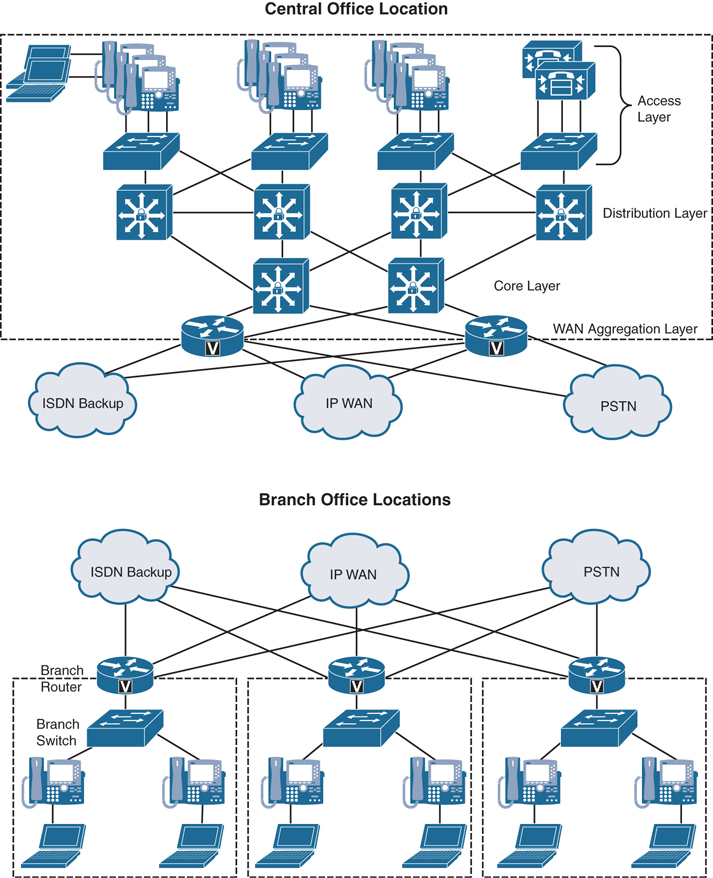
Figure 12-1 Typical Enterprise Network Infrastructure
LAN
A properly designed LAN will take into consideration the needs for high availability and quality of service. This will account for the Access layer, Distribution layer, and Core layer of the typical enterprise network infrastructure. The Access layer offers in-line power to the phones, multiple queue support, 802.1p and 802.1q, and fast link convergence. The Distribution and Core switches offer multiple queue support as well as 802.1p and 802.1q, the same as the Access layer, along with traffic classification and reclassification. An IEEE protocol, 802.1p refers to the support of QoS on Layer 2 switches. Also an IEEE protocol, 802.1Q refers to the support of virtual LANs on Layer 2 switches.
Access Layer
High availability can be configured on the Access layer by using the Spanning Tree Protocol (STP). STP is a Layer 2 protocol that runs on switches and is specified by the IEEE standard 802.1d. The purpose of STP is to prevent loops when configuring redundant paths within the network. In Figure 12-1, observe that each switch is connected to two or more other switches, so that if one path fails, there is a redundant path to the destination. On the switch ports, STP can be configured to block traffic on one port and forward traffic on the other port. In the event that the forwarding port can no longer send and receive communications, the state of the blocking port will change to allow the data to flow along the alternate path. This ensures that there is an alternate path for routing traffic but eliminates the chance of a loop occurring with two open ports. Different flavors of STP can be used, and each one requires different timing for convergence. Therefore, it is recommended that the same version of STP be used within a single environment. Some of the other Spanning Tree Protocols that exist include IEEE 802.1w Rapid Spanning Tree Protocol (RSTP) and IEEE 802.1s Multiple Instance Spanning Tree Protocol (MISTP). These two can converge at much higher rates than the traditional STP.
A virtual local-area network, or VLAN, is another essential part of the Access layer switch, and it should be configured prior to setting up STP. A VLAN is a logical grouping of devices connected to the switch that allows data traffic in the network to be decoupled for access control and prioritization. VLANs can be used to group devices in several ways, such as device type or department. For example, there may be a server where accounting software resides. The accounting team needs access to this software, but the sales team does not need access. The accounting team also needs to be able to communicate with the sales team for handling expense reports. In this scenario, three VLANs can be used to control who can access the accounting software. The server where the software resides can be placed in VLAN110, the accounting team computers can be placed in VLAN120, and the sales team computers can be placed in VLAN130. Then the network administrator can create connections from VLAN120 to VLAN110, and from VLAN120 to VLAN130. This will allow the accounting team to access the accounting software and communicate with the sales team. However, the sales team will be restricted from accessing the accounting software.
In a Cisco collaboration environment, VLANs are essential to implementing proper QoS. At least two VLANs should be created in this environment: a data VLAN and a voice and video VLAN, which is typically signified as VVID (Voice VLAN ID). Voice and video data can traverse the same VLAN, even though they typically experience different QoS markings. The reason these two VLANs need to be created is that Cisco phones have a NIC connecting the phone to a switch and a computer NIC connecting a computer to the phone. The phone and the computer require different QoS treatment and therefore should belong in different VLANs. This is where the configuration gets really interesting. If the phone is connected to the switch and the computer is connected to the phone, how can they possibly be decoupled into different VLANs? On the port at the switch where the phone is connected, both the Data VLAN and the VVID can be assigned. When the phone boots up, CDP or LLDP-MED can be used to discover both of these VLANs. There is a third virtual NIC in the phone that exists to monitor egress traffic and determine which VLAN should be used. Data traffic sourced from the computer will use the Data VLAN. Voice and video data from the phone will use the VVID. If content is being shared from the computer during a video call, then the VVID will be used for that particular data sourced from the computer.
One final offering that can be utilized at the Access layer needs to be mentioned here: inline power. Inline power, or Power over Ethernet (PoE), has already been discussed at great length. For a review of the information coving PoE, refer to Chapter 9, “Endpoint Registration.” Table 12-2 outlines the different types of PoE and the maximum power available. Some examples of Cisco switches that support the different types of PoE can also be found in Table 12-2.
Table 12-2 PoE Types and Supported Power
PoE Type |
PoE Power Capabilities |
Example Switches |
|---|---|---|
Pre-Standard Inline Power |
6.3 Watts power |
3550-24 or 48 ports |
802.3af PoE |
15.4 Watts power (Type 1) |
3560-24 ports or 3670-48 ports |
802.3at PoE |
30 Watts power (Type 2) |
2960-24 is Type 1 or Type 2 |
60 Watts power (Type 3) |
4500 supports all types of PoE |
|
100 Watts power (Type 4) |
9000 supports all types of PoE |
Distribution Layer
The Distribution layer switches can offer the same multiple queue support, 802.1p, 802.1q, and fast link convergence as the Access layer. However, the focus of the Distribution layer should be to offer Layer 3 routing, load balancing, and fault tolerance. These Distribution layer switches are the bridge between Layer 2 and Layer 3 of the enterprise network.
The Distribution layer switch can often serve as the Layer 3 default gateway for the Layer 2 devices. Should the Distribution layer switch fail, then many devices could lose communication across the network. Cisco initially released the Hot Standby Router Protocol (HSRP) to provide a fault-tolerant default gateway. The IETF developed a similar protocol called the Virtual Router Redundancy Protocol (VRRP) with RFC 5798. Although these two protocols are similar in nature and resolve the gateway redundancy issue, they are not compatible protocols and they each have some limitations. Cisco overcame these limitations when it released another protocol called the Gateway Load Balancing Protocol (GLBP). This protocol protects data traffic from a failed router or circuit, while also allowing packet load sharing between a group of redundant routers.
Endpoints use the Address Resolution Protocol (ARP) to learn the physical MAC address of their default gateway. With HSRP, a single virtual MAC address is provided to these endpoints. With GLBP, two virtual MAC addresses can be provided to the endpoints—one from the primary gateway and one from a peer gateway—which are distributed using round-robin technique.
Another way to ensure fast convergence, load balancing, and fault tolerance on the Distribution layer is to use Layer 3 routing protocols such as OSPF or EIGRP. You can use parameters such as routing protocol timers, path or link costs, and address summaries to optimize and control convergence times as well as to distribute traffic across multiple paths and devices. Cisco also recommends using the passive-interface command to prevent routing neighbor adjacencies via the access layer. These adjacencies are typically unnecessary, and they create extra CPU overhead and increased memory utilization because the routing protocol keeps track of them. By using the passive-interface command on all interfaces facing the access layer, you prevent routing updates from being sent out on these interfaces, and therefore, neighbor adjacencies are not formed.
Core Layer
The Core layer operates entirely in Layer 3 of the enterprise network. This layer can consist of Layer 3 switches or routers. The purpose of the Core layer is to provide redundancy between different Distribution switches. In the event of network outages, the Core layer can redirect traffic along a more stable path. The types of redundancy that need to be provided at the Core layer include Layer 1 link paths, redundant devices, and redundant device subsystems, such as power supplies and module cards. The Cisco Catalyst switches with Virtual Switching System (VSS) provide a method to ensure redundancy in all of these areas by pooling together two Catalyst supervisor engines to act as one. This is why Cisco recommends using a Layer 3 switch at the Core layer. Routing protocols at the Core layer should again be configured and optimized for path redundancy and fast convergence. There should be no STP in the core because network connectivity should be routed at Layer 3. Finally, each link between the core and distribution devices should belong to its own VLAN or subnet and be configured using a 30-bit subnet mask.
In the campus LAN, bandwidth provisioning recommendations can be summarized by the motto “overprovision and undersubscribe.” This motto implies careful planning of the LAN infrastructure so that the available bandwidth is always considerably higher than the load and there is no steady-state congestion over the LAN links. The addition of voice traffic onto a converged network does not represent a significant increase in overall network traffic load; the bandwidth provisioning is still driven by the demands of the data traffic requirements. The design goal is to avoid extensive data traffic congestion on any link that will be traversed by telephony signaling or media flows. Contrasting the bandwidth requirements of a single G.711 voice call (approximately 86 kbps) to the raw bandwidth of a Fast Ethernet link (100 Mbps) indicates that voice is not a source of traffic that causes network congestion in the LAN, but rather it is a traffic flow to be protected from LAN congestion.
WAN
The next layer in the enterprise network solution is the WAN Aggregation layer. These are the edge routers that allow different locations to communicate over the public Internet. There are general design considerations for deploying a WAN, as well as specific bandwidth considerations. There are also QoS tools at the WAN that will need careful design because the WAN presents the greatest potential for congestion. QoS topics will be discussed in the next chapter.
The Cisco recommendation when designing the WAN Aggregation layer is to establish multiple links for redundancy in case one of the links should fail. WAN designs include hub and spoke, full mesh, and partial mesh. The hub-and-spoke design contains one central “hub” router connected to multiple “spoke” routers. Each spoke is one hop away from the hub and two hops away from other spokes. Alternatively, a full mesh or partial mesh design could be implemented. In this type of design, multiple WAN links are established between locations so that each location has at least two WAN links, each link to a different router. Redundancy should be built into the WAN Aggregation layer using multiple links. This will ensure connectivity in the event one link fails, and additional bandwidth can be provisioned for load-balancing network traffic. Another design consideration for WAN Aggregation is noncentralized resources so that these services are available to all locations in the event of a WAN failure. These resources include media resources, DHCP servers, voice gateways, and call-processing applications. Earlier in this chapter, we discussed some of the call-processing applications such as SRST or Cisco Unified Communications Manager Express. If you are unfamiliar with these call-processing applications, you may want to research them on your own because they are outside the scope of this book.
The two types of bandwidth options to choose from when designing the WAN Aggregation layer are best-effort bandwidth and guaranteed bandwidth. Examples of best-effort bandwidth include the public Internet, DSL, cable, satellite, and wireless. With best effort there is no QoS, and bandwidth availability is on a first-come basis. Although these types of links are suitable for home offices or commuters, voice and video traffic will suffer. Therefore, Cisco recommends that you do not use best effort for voice-enabled networks that require enterprise-class voice services and quality.
Alternatively, you can choose from available guaranteed bandwidth link options. Leased Lines, Frame Relay, Asynchronous Transfer Mode (ATM), and ATM/Frame-Relay Service Interworking are older technologies that use dedicated circuits through a telephony service provider. These were the best options available to corporations prior to the introduction of broadband and high-speed Internet. Today, these technologies are very expensive and offer lower bandwidth rates compared to other packet-switched solutions available.
Some other guaranteed bandwidth link options available include Multiprotocol Label Switching (MPLS), Cisco Voice and Video Enabled IP Security Virtual Private Network (IPSec V3PN), and Dynamic Multipoint Virtual Private Network (DMVPN). MPLS is a transport protocol that uses “labels” to route traffic rather than network addresses. Packets are forwarded based on the content of the label, so deciphering between voice, video, and data is simple. It is protocol agnostic, so it will function in circuit-switched or packet-switched networks. IPSec V3PN integrates three core Cisco technologies: IP Telephony, QoS, and IPSec VPN. This results in an end-to-end VPN service that can guarantee the delivery of latency-sensitive voice and video communications. DMVPN is a solution that provides an alternative to the complicated administrative setup and maintenance that comes with establishing a mesh network. Initially, the DMVPN is set up as a hub-and-spoke network. Once communication is established between the spokes and the hub, each spoke will dynamically discover each of the other spokes and establish a tunnel between one another. This will reduce the amount of traffic at the hub, preserving bandwidth and processing capacity limits. For information on the deployment of multisite DMVPN WANs with centralized call processing, refer to “Cisco Unified Communications Voice over Spoke-to-Spoke DMVPN Test Results and Recommendations,” available at https://www.cisco.com/go/designzone. Figure 12-2 illustrates how a DMVPN network operates.
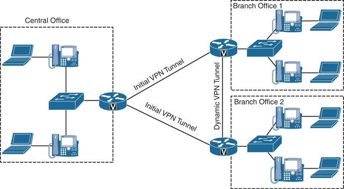
Figure 12-2 DMVPN Network Operations
WLAN
The wireless local-area network (WLAN) is a whole infrastructure deployment that hangs off the LAN but requires a unique set of configurations. WLAN infrastructure design becomes important when collaboration endpoints are added to the WLAN portions of a converged network. With the introduction of Cisco Unified Wireless endpoints, voice and video traffic has moved onto the WLAN and is now converged with the existing data traffic there. Just as with wired LAN and wired WAN infrastructure, the addition of voice and video in the WLAN requires following basic configuration and design best practices for deploying a highly available network. In addition, proper WLAN infrastructure design requires understanding and deploying QoS on the wireless network to ensure end-to-end voice and video quality on the entire network.
Basic Configuration and Design
Wireless IP network architectures enable IP telephony to deliver enterprise mobility by providing on-premises roaming communications to the users with wireless IP telephony devices. Wireless IP telephony and wireless IP video telephony are extensions of their wired counterparts, which leverage the same call elements. Additionally, wireless IP telephony and IP video telephony take advantage of wireless 802.11-enabled media, thus providing a cordless IP voice and video experience. The cordless experience is achieved by leveraging the wireless network infrastructure elements for the transmission and reception of the control and media packets. The architecture for voice and video over wireless LAN includes the following basic elements:
Wireless access points
Wireless LAN controllers
Authentication database
Supporting wired network
Wireless collaboration endpoints
Wired call elements
The wireless access points enable wireless devices to communicate with wired network elements. In the case of a Cisco Collaboration environment, these wireless devices include all the UC voice and video endpoints that support wireless communications. Access points function as adapters between the wired and wireless world, creating an entryway between these two media components. Cisco access points can be managed by a wireless LAN controller (WLC), or they can function in autonomous mode. When the access points are managed by a WLC, they are referred to as lightweight access points (LWAPs), and in this mode, they use the Lightweight Access Point Protocol (LWAPP) or Control and Provisioning of Wireless Access Points (CAPWAP) protocol, depending on the controller version, when communicating with the WLC.
Many corporate environments require deployment of wireless networks on a large scale. The wireless LAN controller (WLC) is a device that assumes a central role in the wireless network and helps make it easier to manage such large-scale deployments. Traditional roles of access points, such as association or authentication of wireless clients, are handled by the WLC. Access points, called lightweight access points in the Unified Communications environment, register themselves with a WLC and tunnel all the management and data packets to the WLCs, which then switch the packets between wireless clients and the wired portion of the network. All the configurations are done on the WLC. LWAPs download the entire configuration from WLCs and act as a wireless interface to the clients. Figure 12-3 illustrates the relationship between the WLC and the LWAP.

Figure 12-3 WLC Deployment with LWAP
The authentication database is a core component of the wireless networks, and it holds the credentials of the users to be authenticated while the wireless association is in progress. The authentication database provides network administrators with a centralized repository to validate the credentials. Network administrators simply add the wireless network users to the authentication database instead of having to add the users to all the wireless access points with which the wireless devices might associate. In a typical wireless authentication scenario, the WLC couples with the authentication database to allow the wireless association to proceed or fail. Authentication databases commonly used are LDAP and RADIUS, although under some scenarios the WLC can also store a small user database locally that can be used for authentication purposes.
The supporting wired network is the portion of the system that serves as a path between WLCs, WAPs, and wired call elements. Because the WAPs need to communicate to the wired world, part of the wired network has to enable those communications. The supporting wired network consists of the LAN switches, routers, and WAN links that work together to communicate with the various components that form the architecture for voice and video over WLAN.
The wireless collaboration endpoints are the user-facing voice and video nodes that operate over the WLAN, which are used for communication. These endpoints can be voice only or enabled for both voice and video. When end users employ the wireless communication endpoints to call a desired destination, the endpoints in turn forward the request to their associated call-processing server. If the call is allowed, the endpoints process the voice or video, encode it, and send it to the receiving device or the next hop of processing. Typical Cisco wireless endpoints are wireless IP phones, voice and video software clients running on desktop computers, mobile smartphones connected through wireless media, and mobile collaboration enterprise tablets. Specifically, the Cisco Unified IP Phones 7861, 8861, and 8865 support wireless communication. Any Windows or Mac computer running the Cisco Jabber application, or any smartphone or tablet running Jabber, could be connected wirelessly to the network. Also, the Cisco DX series endpoints support wireless connections to the network.
Whether the wireless collaboration endpoints initiate a session between each other or with wired endpoints, wired call elements are involved in some way. Wired call elements, such as gateways and call-processing entities, are the supporting infrastructure for voice and video endpoints coupled to that infrastructure. Figure 12-4 illustrates all of the components needed in a WLAN deployment.
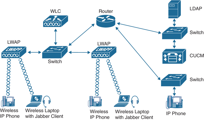
Figure 12-4 Components of a Full WLAN Deployment
High Availability
Providing high availability in collaboration solutions is a critical requirement for meeting the modern demands of continuous connectivity. Collaboration deployments designed for high availability increase reliability and uptime. Using real-time applications such as voice or video over WLAN without high availability could have very adverse effects on the end-user experience, including an inability to make voice or video calls.
A unique aspect of high availability for voice and video over WLAN is high availability of radio frequency (RF) coverage to provide Wi-Fi channel coverage that does not depend on a single WLAN radio. The Wi-Fi channel coverage is provided by the AP radios in the 2.4 GHz and 5 GHz frequency bands.
The primary mechanism for providing RF high availability is cell boundary overlap. In general, a cell boundary overlap of 20 to 30 percent on nonadjacent channels is recommended to provide high availability in the wireless network. For mission-critical environments, at least two APs should be visible at the required signal level (−67 dBm or better). An overlap of 20 percent means that the RF cells of APs using nonadjacent channels overlap each other on 20 percent of their coverage area, while the remaining 80 percent of the coverage area is handled by a single AP. Furthermore, when determining the locations for installing the APs, you should avoid mounting them on reflective surfaces, such as metal, glass, and so forth, which could cause multipath effects that result in signal distortion. Figure 12-5 illustrates a high availability deployment of WLANs using overlapping channel cells.
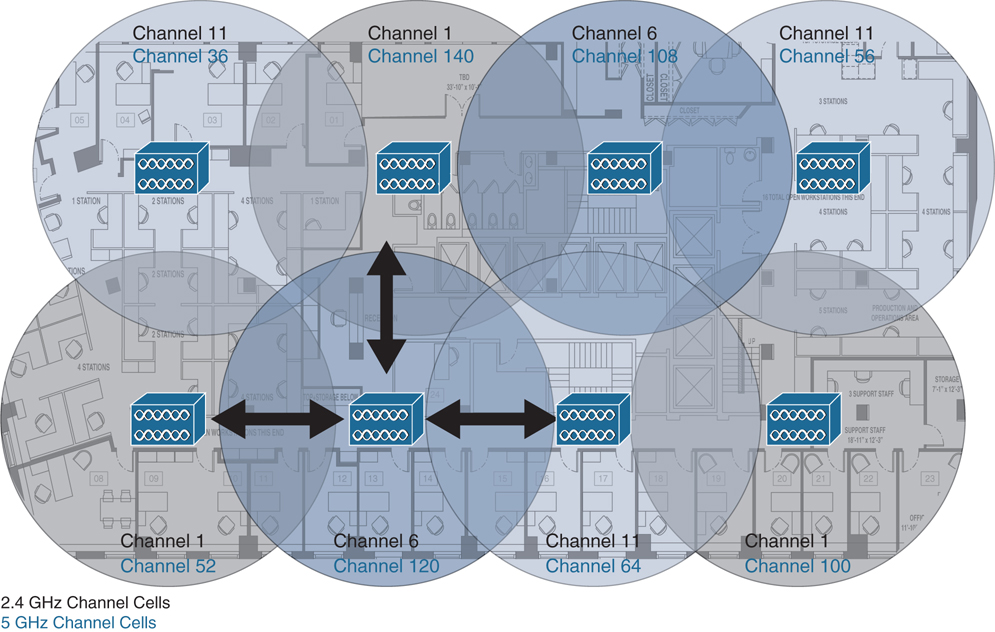
Figure 12-5 High Availability Deployment of WLANs Using Overlapping Channel Cells
Careful deployment of APs and channel configuration within the wireless infrastructure are imperative for proper wireless network operation. For this reason, Cisco requires customers to conduct a complete and thorough site survey before deploying wireless networks in a production environment. The survey should include verifying nonoverlapping channel configurations, Wi-Fi channel coverage, and required data and traffic rates; eliminating rogue APs; and identifying and mitigating the impact of potential interference sources. Additionally, you should evaluate utilizing a 5 GHz frequency band, which is generally less crowded and thus usually less prone to interference. If Bluetooth is used, it is highly recommended to use a 5 GHz WLAN band (802.11a/n/ac) whenever possible for endpoint connectivity. Similarly, the use of Cisco CleanAir technology will increase the WLAN reliability by detecting radio frequency interference in real time and providing a self-healing and self-optimizing wireless network.
Capacity Planning
A crucial piece in planning for voice and video over WLAN is adequately sizing the solution for the desired call capacity. Capacity is defined as the number of simultaneous voice and video sessions over WLAN that can be supported in a given area. Capacity can vary depending on the RF environment, the collaboration endpoint features, and the WLAN system features. For instance, a solution using Cisco Unified Wireless IP Phones 8861 on a WLAN that provides optimized WLAN services would have a maximum call capacity of 27 simultaneous sessions per channel at a data rate of 24 Mbps or higher for both 802.11a and 802.11g. On the other hand, a similar solution with a wireless device such as a tablet running the Jabber client making video calls at 720p and a video rate of 2500 kbps on a WLAN, where access points are configured as 802.11a/n with a data rate index of Modulation and Coding Scheme 7 in 40 MHz channels, would have a maximum capacity of seven video calls and two bidirectional voice and video streams per channel. To achieve these capacities, there must be minimal wireless LAN background traffic and RF utilization, and Bluetooth must be disabled in the devices. It is also important to understand that call capacities are established per nonoverlapping channel because the limiting factor is the channel capacity and not the number of access points (APs). The call capacity specified by the actual wireless endpoint should be used for deployment purposes because it is the supported capacity of that endpoint.
Design Considerations
It is easy to understand that the design and implementation of a WLAN environment in the workplace is very complex and requires many considerations to be factored into the overall network design. Additionally, WLAN configuration specifics can vary depending on the voice or video WLAN devices being used and the WLAN design. Other design considerations for a proper WLAN deployment include the following:
VLANs
Roaming
Wireless channels
Wireless interference and multipath distortion
Multicast on the WLAN
Wireless AP configuration and design
Wireless LAN controller design considerations
WLAN quality of service
An entire series of books could be written just to cover the WLAN components and considerations that must be accounted for in a network design that supports voice and video communications. Cisco has a CCNP and CCIE certification track that deals with the many facets of a WLAN environment, and many resources are available to extend an engineer’s understanding of these solutions. To keep the contents of this section relevant to the scope of this book, we will not cover the preceding topics. However, the next chapter will delve into some of the WLAN QoS settings that need to be configured to support voice and video over a WLAN environment.
Gateways
Gateways provide a number of methods for connecting a network of collaboration endpoints to the public switched telephone network (PSTN), a legacy PBX, or external systems. Voice and video gateways range from entry-level and standalone platforms to high-end, feature-rich integrated routers, chassis-based systems, and virtualized applications.
During the 1990s and early 2000s, the only way for an enterprise to connect its internal voice and video network to services outside the enterprise was by means of time-division multiplexing (TDM) or serial gateways through the traditional PSTN. Cisco still offers a full range of TDM and serial gateways with analog and digital connections to the PSTN as well as to PBXs and external systems. TDM connectivity covers a wide variety of low-density analog (FXS and FXO), low-density digital (BRI), and high-density digital (T1, E1, and T3) interface choices. Starting around 2006, new voice and video service options to an enterprise became available from service providers, often as SIP trunk services. Using a SIP trunk for connecting to the PSTN and other destinations outside the enterprise involves an IP-to-IP connection at the edge of the enterprise’s network. The same functions traditionally fulfilled by a TDM or serial gateway are still needed at this interconnect point, including demarcation, call admission control, quality of service, troubleshooting boundary, security checks, and so forth. For voice and video SIP trunk connections, the Cisco Unified Border Element and the Cisco Expressway Series fulfill these functions as an interconnection point between the enterprise and the service provider network.
There are two types of Cisco TDM gateways: analog and digital. Both types support voice calls, but only digital gateways support video. The two categories of Cisco analog gateways are station gateways and trunk gateways. Analog station gateways connect the Cisco Unified Communications Manager to plain old telephone service (POTS) analog telephones, interactive voice response (IVR) systems, fax machines, and voicemail systems. Station gateways provide foreign exchange station (FXS) ports. Analog trunk gateways connect the Cisco Unified Communications Manager to PSTN central office (CO) or PBX trunks. Analog trunk gateways provide foreign exchange office (FXO) ports for access to the PSTN, PBXs, or key systems, and E&M (recEive and transMit, or ear and mouth) ports for analog trunk connection to a legacy PBX. Analog Direct Inward Dialing (DID) and Centralized Automatic Message Accounting (CAMA) are also available for PSTN connectivity. Cisco analog gateways are available on the following products and series:
Cisco Analog Voice Gateways VG204XM and VG300 Series (VG310, VG320, VG350) all support SCCP.
Cisco Integrated Services Routers Generation 2 (ISR G2) 2900, 3900, 3900E, and 4000 Series (4300 and 4400) with appropriate PVDMs and service modules or cards. PVDM4s utilized by ISR 4000 Series do not support video today.
Cisco Analog Telephone Adapter (ATA) 190 (SIP only) provides a replacement for the ATA188.
A Cisco digital trunk gateway connects the Cisco Unified Communications Manager to the PSTN or to a PBX via digital trunks such as Primary Rate Interface (PRI), Basic Rate Interface (BRI), serial interfaces (V.35, RS-449, and EIA-530), or through T1 Channel Associated Signaling (CAS). Digital T1 PRI and BRI trunks can be used for both video and audio-only calls. Cisco digital trunk gateways are available on the following products and series:
Cisco Integrated Services Routers Generation 2 (ISR G2) 1900, 2900, 3900, 3900E, 4300, and 4400 Series with appropriate PVDMs and service modules or cards (The PVDM2 cards were end of life as of June 30, 2019. Cisco recommends using the PVDM3 or PVDM4 cards on appropriate routers.)
Cisco Telepresence ISDN GW 3241 and MSE 8321 (These products were end of sale as of May 2, 2017.)
Cisco Telepresence Serial GW 3340 and MSE 8330 (These products were end of sale as of May 2, 2017.)
The Cisco Telepresence ISDN link is a compact appliance that provides Cisco Telepresence endpoints direct ISDN and external IP network connectivity. This unit is supported on all Cisco Telepresence endpoints running TC or CE software. While traditional voice and video gateways are shared resources that provide connectivity between the IP network and the PSTN for many endpoints, each Cisco ISDN link is paired with a single Cisco endpoint.
ISR, ASR, and IOS Software Comparisons
Cisco has a line of routers that offer advanced services beyond what traditional routers can offer. These routers are ideal for use in voice and video environments as well as support of smaller branch office locations or hybrid communication to the cloud. They are the Integrated Services Routers (ISRs), Aggregation Services Routers (ASRs), and Cloud Services Routers (CSRs). The biggest difference between Cisco ASR and ISR routers is that ASR routers are for enterprises and service providers, whereas ISRs are for customers with small- or medium-sized networks. CSRs go beyond the scope of this book, so the focus will be on the ISR and ASR options.
Two factors that should be considered will influence which of these router product lines should be used within a particular customer environment. Sizing is the most important factor, followed by the software running on the router. Different software will provide different features and capabilities. The classic IOS software was used on all Cisco routers prior to 2007 and may still be found running on some routers in production today. However, most current products in the Cisco ISR and ASR routers use either the IOS XE or IOS XR software version.
Cisco IOS XE software is an open and flexible operating system optimized for a new era of enterprise networks. Its standards-based programmable interfaces automate network operations and give you deep visibility into user, application, and device behaviors. As the single OS for enterprise wired and wireless access, aggregation, core, and WAN, Cisco IOS XE reduces business and network complexity. Cisco IOS XE software is open because it includes the following open standards-based capabilities: NETCONF (RFC 6241) programmable interfaces, IETF YANG push telemetry, OpenConfig and IETF YANG data models, and Guest Shell Linux Containers (LXC). Yet the user interface is the same familiar CLI that engineers have been using throughout the lifecycle of the older classic IOS software. This highly scalable software has been developed with resiliency in mind; Cisco IOS XE reduces planned and unplanned downtime. Service and software upgrades are more efficient, and Graceful Insertion and Removal lets you update or debug a switch without disrupting network traffic. Cisco IOS XE software also has built-in security and trust, which helps protect against modern cyberattacks. It assures that Cisco hardware and software are genuine and unmodified. And its enhanced platform integrity, security, and resilience mean you can be confident that data is trustworthy. Additionally, all IOS XE software-based routers support hybrid cloud services.
IOS XR is Cisco IOS software used on the high-end Network Converging System (NCS), carrier-grade routers such as the CRS Series, 12000 Series, and ASR9000 Series. In fact, the ASR9000 Series are the only ASR or ISR routers that support the IOS XR software. Cisco’s IOS XR software shares very little infrastructure or feature support with the other IOS software options and is instead built on a preemptive, memory-protected, multitasking, microkernel-based operating system. The microkernel was formerly provided by QNX; versions 6.0 and up use the Wind River Linux distribution. IOS XR is an on-premises-only software solution with no hybrid cloud support, and it aims to provide the following advantages over the earlier IOS versions:
Improved high availability (largely through support for hardware redundancy and fault containment methods such as protected memory spaces for individual processes and process restart-ability)
Better scalability for large hardware configurations (through a distributed software infrastructure and a two-stage forwarding architecture)
A package-based software distribution model (allowing optional features such as multicast routing and MPLS to be installed and removed while the router is in service)
The ability to install package upgrades and patches (potentially while the router remains in service)
A web-based GUI for system management (making use of a generic, XML management interface)
As mentioned previously, the number of users the router needs to support for sizing and the software version will determine the specific product needed for a given customer site. Table 12-3 identifies all the different series of ISR and ASR routers available with their sizing limitations and software availability.
Table 12-3 ISR and ASR Routers and Software Options
Router Model |
Software Version |
Sizing Limitations (SRTP/RTP Sessions) |
|---|---|---|
ASR 900 |
IOS XE |
Unknown |
ASR 1000 Series |
IOS XE |
Unknown |
ASR 9000 Series |
IOS XR |
Unknown |
ISRv |
IOS XE |
Up to 1000 |
ISR 1000 |
IOS XE |
75 to 100 |
ISR 4000 Series |
IOS XE |
40 to 1500 |
CSR 1000v |
IOS XE |
225 to 800 (1 or 4 vCPU) |
ISR 800 Series |
Classic IOS |
20 |
ISR 900 Series |
Classic IOS |
50 |
ISR 2900 Series |
Classic IOS |
Up to 200 |
ISR Products Explained
As Table 12-3 shows, you have many product lines to choose from when deploying the Cisco ISR. This section will delve into four specific ISRs: the ISRv (which is a virtual router), 800 Series ISR, 1000 Series ISR, and the 4000 Series ISR. The 800 Series ISR is the only router discussed in this section that runs the classic IOS software instead of the IOS XE software. However, this is a great router to use for remote office locations, and it supports DMVPN.
There are many benefits to using the ISRv. First, it supports rapid deployment and service automation. The virtual form factor accelerates deployment and eliminates hardware costs such as complete equipment upgrades and return materials authorization (RMA). It also supports single-tenant use. This feature allows a cloud service provider to provision a routing instance per tenant, simplifying service delivery and tenant management. It also helps the provider overcome VLAN scale limits, increasing tenant scale. The enterprise network extension to the cloud feature provides enterprises highly secure direct connections from their distributed sites to their cloud-hosted applications, improving application response time and user experience. The network consistency feature uses familiar enterprise-class Cisco IOS software features for consistent network operation across premises and the cloud, allowing the enterprise to view the cloud as just another node in its network. Network scalability allows scale beyond the limitations of 802.1q VLAN tagging by building a VXLAN network or extending Layer 3 routing deeper into the cloud environment. Finally, consolidation of network functions eliminates the facility requirements and complexity of physical network devices by consolidating multiple network functions onto a single piece of server hardware.
The following features are supported on the Cisco ISRv:
Routing: Border Gateway Protocol (BGP), Open Shortest Path First (OSPF), Enhanced Interior Gateway Routing Protocol (EIGRP), Policy-Based Routing, IPv6, Virtual Route Forwarding Lite (VRF-Lite), Multicast, LISP, and Generic Routing Encapsulation (GRE)
Addressing: Dynamic Host Configuration Protocol (DHCP), Domain Name System (DNS), Network Address Translation (NAT), 802.1Q VLAN, Ethernet Virtual Connection (EVC), and VXLAN
VPN: IPsec VPN, DMVPN, Easy VPN, SSL VPN, and FlexVPN
MPLS: MPLS VPN, VRF, and Bidirectional Forwarding Detection (BFD)
Security: Cisco IOS Zone-Based Firewall (ZBFW); access control list (ACL); authentication, authorization, and accounting (AAA); RADIUS; and TACACS+
High availability: HSRP, Virtual Router Redundancy Protocol (VRRP), Gateway Load Balancing Protocol (GLBP), and box-to-box high availability for ZBFW and NAT
Traffic redirection: AppNav (to Cisco Wide Area Application Services [WAAS]) and Web Cache Communication Protocol (WCCP) application visibility, performance monitoring, and control: quality of service (QoS), AVC, and IP service-level agreement (SLA)
Hybrid cloud connectivity: OTV, Virtual Private LAN Service (VPLS), and Ethernet over MPLS (EoMPLS)
Management: Command-line interface (CLI), Secure Shell (SSH) Protocol, NetFlow, Simple Network Management Protocol (SNMP), Embedded Event Manager (EEM), and RESTful application programming interfaces (APIs)
NFV: Virtual route reflector (vRR), virtual broadband network gateway (vBNG), and virtual intelligent services gateway (vISG)
An affordable router series that supports important network services such as security is the Cisco 800 Series Integrated Services Routers. These ISRs deliver secure, reliable WAN connectivity that small offices and remote workers need. Additionally, they support built-in voice features, wireless, WAN optimization, and machine-to-machine communications. Different models in the series support different connection types to serve the specific needs of a small office. That could be xDSL, Wi-Fi, 4G LTE, Ethernet, fiber, or something else. Routing, switching, wireless, and intelligent IP network services are all bundled into one compact form factor that’s quick to install using the Cisco Configuration Professional Express tool. They can all be managed centrally from a data center with Cisco Prime Infrastructure and LiveAction applications. The 800 ISRs provide comprehensive security—encryption, VPN, firewall, and cloud-based URL filtering—to help safeguard customers and data. Table 12-4 outlines the models in the 800 Series ISRs and includes deployment recommendations and top WAN speeds.
Table 12-4 800 Series ISRs
Model |
Deployment Recommendation |
Top WAN Speed with Services On |
|---|---|---|
860 |
Home or small offices with up to 10 users |
10 Mbps |
880 |
Remote workers, small offices, and branch locations with up to 20 users |
15 Mbps |
810 |
Machine-to-machine and device-to-device deployments such as ATMs, point-of-sale, kiosks, vending machines (fixed platform) |
15 Mbps |
890 |
Enterprise remote offices with up to 50 users |
>20 Mbps |
800M |
Microbranches, industrial, Internet of Things/IoT (modular platform) |
Various Cellular Data Rates |
The Cisco 1000 Series ISR platform with its small form factor is best suited for small and midsize businesses, enterprise branches, and as customer premises equipment in managed services environments. The routers come with four or eight LAN ports in various model options. They have high performance with Gigabit Ethernet packet-forwarding capabilities. The multicore architecture has separate cores for the data plane and control plane. The 1000 Series ISRs support Power over Ethernet (PoE) and PoE+ to power branch devices such as IP phones and cameras. They are easy to deploy with zero-touch provisioning using Plug-and-Play capability. There are multiple combinations to choose from, including LAN, WLAN, WAN, DSL, LTE, and pluggable, depending on your branch needs. The 1000 Series can be used in ATMs, retail stores, and kiosks, as well as for various other purposes. The 1000 Series ISRs address the demands of increased mobility with LTE Advanced and 802.11ac (Wave 2) Wi-Fi. It has a comprehensive set of WAN connectivity options such as Ethernet, Fiber, LTE, and the latest DSL technologies, like G.fast. The routers provide a great return on investment, allowing you to save on operating expenses by reducing WAN link costs with software-defined WAN capability and transport independence using Cisco SD-WAN. You can also reduce capital expenses using pay-as-you-grow licensing for IPsec performance. The 1000 Series ISRs answer the latest security threats to networking devices with advanced features such as zone-based firewall, Trustworthy Systems, Cisco Umbrella security, and Encrypted Traffic Analytics.
The Cisco 1000 Series ISRs include the following models:
Cisco 1100-8P ISR with LTE Advanced
Cisco 1100-4P ISR with DSL
Cisco 1101-4P
Cisco 1101-4PLTEP
As you build out the digital capabilities in your enterprise branch offices, you should consider the full-service sophistication of the Cisco 4000 Series Integrated Services Routers. The 4000 Series ISRs consolidate many must-have IT functions, including network, security, compute, storage, and unified communications. So, you get everything you need in a single platform. That means significant savings in capital, operational, and management expenses for lower total cost of ownership. The platform is modular and upgradable, so you can add new services without changing equipment. It supports multiple application-aware services concurrently while maintaining WAN performance of up to 2 Gbps, even during heavy traffic loads. The backplane architecture supports high-bandwidth, module-to-module communication at speeds up to 10 Gbps. The 4000 Series includes Cisco Trust Anchor Technologies that help mitigate modern cyberattacks by verifying platform integrity and providing protection from counterfeit and unauthorized modification of hardware and software.
The 4000 Series runs Cisco Intelligent WAN (IWAN), a comprehensive set of traffic control and security features. IWAN includes all the business-grade capabilities of a Multiprotocol Label Switching (MPLS) VPN using other types of less-expensive links, such as per-application traffic management, WAN optimization, and VPN tunneling, which can be put to work across Internet, cellular, and other lower-cost services as connections are added. Additionally, new router services can be activated on demand through a simple licensing change. Local IT staff are not needed in the branch to deliver a fully comprehensive computing and networking experience with remote application installation and management capabilities.
Cisco IWAN features can now be configured in next to no time, thanks to Cisco’s enterprise software-defined networking (SDN) controller, the Application Policy Infrastructure Controller Enterprise Module (APIC EM). APIC EM allows automation of lots of tasks across the network. You can implement an SDN on the Cisco WAN infrastructure without having to upgrade any equipment; just install the no-charge APIC EM software-based controller between applications and network infrastructure. The controller translates business policy directly into network device-level policy for automatic compliance with any corporate and industry-mandated polices. For additional WAN management simplicity, you can also use the IWAN app for APIC EM. The app automates the configuration of Cisco Intelligent WAN features, such as quality of service, WAN optimization, and security, in Cisco branch and edge WAN routers. The app slashes what used to require 1000 CLI steps to just 10 mouse clicks per site. With the IWAN app’s template functionality, the ability to configure, deploy, and manage large numbers of branch offices has never been easier. The 4000 Series ISR contains these platforms: the 4451, 4431, 4351, 4331, 4321, and 4221 ISRs.
APIC EM is now wrapped into DNA Center, which falls under SD-Access. It could also be described as “Cisco’s Software-Defined Access (SD-Access) solution” because it’s the blanket term of the software-defined LAN side. Also, to add to the confusion, APIC EM and IWAN are still being used, but more attention is focused on the Cisco SD-WAN solution that’s based on the Viptela acquisition. Lastly, both SD-Access and SD-WAN fall under Cisco Digital Network Architecture (Cisco DNA), similar to how everything in collaboration now falls under Webex.
Exam Preparation Tasks
As mentioned in the section “How to Use This Book” in the Introduction, you have a couple of choices for exam preparation: the exercises here, Chapter 32, “Final Preparation,” and the exam simulation questions in the Pearson Test Prep Software Online.
Review All Key Topics
Review the most important topics in this chapter, noted with the Key Topics icon in the outer margin of the page. Table 12-5 lists a reference of these key topics and the page numbers on which each is found.
Table 12-5 Key Topics for Chapter 12
Key Topic Element |
Description |
Page Number |
|---|---|---|
Paragraph |
LAN Communication and Layer 2 Switches Overview |
281 |
Paragraph |
Layer 3 Routers and Basic Services They Provide |
282 |
Paragraph |
Medianet Explained |
283 |
Paragraph |
Spanning Tree Protocol Explained |
285 |
Paragraph |
VLANs Explained |
285 |
PoE Types and Supported Power |
286 |
|
Paragraph |
Comparison of HSRP, VRRP, and GLBP |
286 |
Paragraph |
WAN Aggregation Design Models |
287 |
Paragraph |
DMVPN Explained |
288 |
List |
Basic Elements of a WLAN |
289 |
Paragraph |
Examples of Wireless Voice and Video Endpoints |
291 |
Paragraph |
Cell Boundary Overlap |
292 |
List |
WLAN Design Considerations |
293 |
Paragraph |
Gateway Categorization |
294 |
ISR and ASR Routers and Software Options |
296 |
|
List |
ISRv Features Supported |
297 |
800 Series ISRs |
298 |
|
List |
Cisco 1000 Series ISR Models |
299 |
Define Key Terms
Define the following key terms from this chapter and check your answers in the glossary:
Q&A
The answers to these questions appear in Appendix A. For more practice with exam format questions, use the Pearson Test Prep Software Online.