
Chapter 10
Call Settings on Cisco CE Software-Based Endpoints
This chapter covers the following topics:
Calling Options: This topic will discuss the various ways calls can be placed from CE software-based endpoints.
Content Sharing Options: This topic will discuss the various options available for sharing content through a CE software-based endpoint both locally and during a call.
Other Options: Various other options can be leveraged from CE software-based endpoints. This topic will introduce the function of these other options and how they can be configured.
The previous chapter mentioned settings that can be configured on CE software-based endpoints that cannot be configured on Cisco Unified IP phones. H.323 and SIP registration settings are only some of the features that set these intelligent systems apart. This chapter will delve into some of the other features that uniquely identify the superiority of CE software-based endpoints. Topics discussed in this chapter include the following:
Calling Options:
Call by Alias
Call by Directory
Multipoint Calling
One Button to Push (OBTP) and Scheduled Conferences
Content Sharing Options:
Direct Sharing Content
Using Intelligent Proximity for Content Sharing
Other Options:
Audio Settings
Encryption Mode
AutoAnswer
Far-End Camera Control (FECC)
Phonebook
Video Settings
“Do I Know This Already?” Quiz
The “Do I Know This Already?” quiz allows you to assess whether you should read this entire chapter thoroughly or jump to the “Exam Preparation Tasks” section. If you are in doubt about your answers to these questions or your own assessment of your knowledge of the topics, read the entire chapter. Table 10-1 lists the major headings in this chapter and their corresponding “Do I Know This Already?” quiz questions. You can find the answers in Appendix A, “Answers to the ‘Do I Know This Already?’ Quizzes.”
Table 10-1 “Do I Know This Already?” Section-to-Question Mapping
Foundation Topics Section |
Questions |
|---|---|
Calling Options |
1–4 |
Content Sharing Options |
5–6 |
Other Options |
7–11 |
Caution
The goal of self-assessment is to gauge your mastery of the topics in this chapter. If you do not know the answer to a question or are only partially sure of the answer, you should mark that question as wrong for purposes of the self-assessment. Giving yourself credit for an answer you correctly guess skews your self-assessment results and might provide you with a false sense of security.
1. Which of the following user interface control devices can be used on the Cisco DX80 endpoint?
TRC5 Remote Control
Touchscreen
Touch 10 control pad
Web interface
2. How many directory entries can a Cisco CE software-based endpoint hold locally within the endpoint database?
35
350
3500
35,000
3. Which of the following terms is defined by any call involving three or more participants?
Multipoint
Multisite
Multiway
Ad hoc
4. Which of the following devices can be used to schedule OBTP meetings?
CUCM
VCS
TMS
CMS
5. Which of the following is the ITU standard for content sharing?
DuoVideo
People+Content
H.224
H.239
BFCP
6. Which of the following devices can initiate content being shared via the Proximity application?
Windows computer
Smartphone
Tablet
Cisco Unified IP phone
7. Which of the following statements is true?
The Microphone Mute Enabled setting will mute the microphone when a call is set up.
The Microphone Mute Enabled setting will not mute the microphone when a call is set up.
The Input Microphone Mode setting will mute the microphone when a call is set up.
The Input Microphone Mode setting determines which microphone is set as the primary.
8. Which of the following is the default Encryption Mode setting on a CE software-based endpoint?
AES 128
AES 256
On
Best Effort
9. Which of the following is the standard for FECC?
H.224
H.239
T.150
BFCP
10. Which of the following directories requires the endpoint to send a subscribe message before phonebook entries can be retrieved?
Local directory
Global directory
Corporate directory
Both global and corporate directories
No directory requires a subscribe message before phonebooks can be received.
11. The RGB Quantization Range setting overrides devices that do not follow the CEA-861 standard in order to provide the perfect image with any display. Which of the following settings is used to set the RGB quantization range based on the RGB Quantization Range bits (Q0, Q1) in the AVI infoframe?
Auto
Full
Limited
Manual
None of these answers are correct.
Foundation Topics
Calling Options
Because the primary purpose of having an endpoint is to be able to place and answer calls, it is important to understand how to use these systems once they have registered to the call control system of your choosing. A call can be placed or answered from CE software-based systems in essentially three ways:
Call out or answer an incoming call from the user interface. This could be the Touch 10 controller, a remote control, or a touchscreen on the endpoint, depending on which device is being used. This could also be a personal device, such as a smartphone or tablet, through the Proximity application.
Use the web interface.
Use the command-line interface (CLI).
An administrator typically uses the web interface and CLI. Because end users will be sitting in front of the system, they would interact with the user interface.
Calls from a CE software-based endpoint can be made by dialing the destination alias or by selecting a participant from the directory, or phone book. Multipoint conference meetings can be arranged by dialing into a bridge that will host the meeting or by utilizing the Multisite option on the CE endpoint itself. The Multisite option is a licensed feature that must be added to the CE software-based endpoint before this feature can be used. Scheduled meetings can be accessed in a variety of ways as well, such as using a feature called One Button to Push (OBTP). The following sections will delve into each of these dialing behaviors to provide a more thorough understanding of call behavior and how to configure settings related to each of these calling components.
Call by Alias
Since the invention of automatic telephony switches, the most common means of initiating communication with another party, whether through a PSTN telephone, IP phone, or video phone, has been by dialing the alias of the destination. Traditional PSTN phones and most IP phones use E.164 aliases to dial, which is more commonly known as the telephone number. In the case of the Cisco Unified Communications Manager, these aliases are known as directory numbers (DNs). However, as explained already in previous chapters, other alias types can be used, and they are growing in popularity. The most common type of alias used outside of E.164 aliases is the SIP URI. Regardless of the alias type, the endpoint used to place calls must possess the ability to dial the destination alias. All Cisco CE software-based endpoints share a common interface so that no matter what Cisco Telepresence endpoint is being used, the experience will be the same for every user. The following figures and descriptions are based on the Cisco DX80 endpoint, but they can be applied to any DX, MX, SX, IX, or Webex Telepresence endpoint.
Users can use three different control mechanisms available on Cisco CE software-based endpoints to interact with the different systems. The Cisco SX10 endpoint comes with a TRC5 remote control. The DX80 endpoint has a touch control screen, and all other Cisco endpoints come with a Touch 10 control pad. Regardless of which control device is being used on the Cisco endpoints, the screen layouts and menu options are the same. Figure 10-1 illustrates the menu layout options on a Cisco DX80 touchscreen.
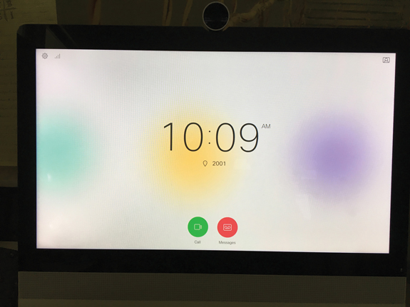
Figure 10-1 Cisco DX80 Touchscreen Menu Layout
On the user interface, the time of day will always be displayed on the center of the screen. There is an option to set this to a 12-hour or 24-hour clock when the system is set up for the first time. In the top-right corner of the screen is an icon with a person displayed on a screen. If you select this option, a self-view window will appear. Once displayed, the self-view window can be moved to six different points around the screen: the top-left corner, top-right corner, middle-left edge, middle-right edge, bottom-left corner, or bottom-right corner. The gear icon in the top-left corner will bring up some selective menu options. The menus available from the top down are Do Not Disturb, Light Adjustment Bar, Forward All Calls To…, Forward All Calls to Voicemail, System Information, and Standby. The System Information menu will provide the endpoints’ video address, IP address, MAC address, SIP Proxy, software version, and device type. The Settings button along the bottom of the screen will allow you to view and change some extended settings on the endpoint. However, advanced settings need to be configured from the web interface or the CLI.
At the bottom of the main screen, located under the clock, are two circles. The red circle is a direct access to a voicemail box, and the green circle is used for calling. If you select the green Call button, a dial box will display. When you select the dial box, a QWERTY keyboard with a numeric dialpad will display at the bottom of the screen. This allows for easier dialing of both SIP URIs and E.164 aliases. You can enter the alias of the destination and click the green Call button that appears to the right. This Call button will not appear until you start typing a destination alias. Once the Call button is pressed, the destination alias will ring, and the call will connect when the far-end participant answers the call. Figure 10-2 illustrates the call settings for dialing by alias from the user interface.

Figure 10-2 Cisco DX80 Dial by Alias Settings from User Interface
Another way to dial from an endpoint is to use the Intelligent Proximity for Content Sharing application from a Windows or Mac computer, smartphone, or tablet. Once the Proximity application pairs with the endpoint, a dial box will appear in the middle of the screen. When you tap inside this box, a keyboard will display at the bottom of the screen. You can dial the alias of the destination endpoint and tap the green Call button. The endpoint, not the Proximity app, will dial out to the destination. Once the call has connected, you can use the Proximity app to adjust the volume on the endpoint, receive content being shared, scroll through previously shared content, and save content to the Photos library on your device. There is also an End button on the Proximity app to hang up a call, and when the endpoint is being called, an Answer button will appear. Figure 10-3 illustrates some of the functionality that exists with Intelligent Proximity.
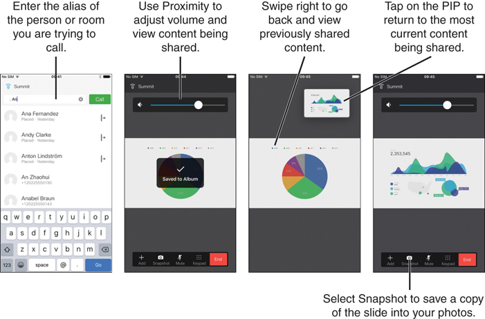
Figure 10-3 Dialing from an Endpoint Using Proximity
The next two options for dialing out from a Cisco CE software-based endpoint using the alias of a destination are only used typically by an administrator. The web interface or CLI allows an administrator to dial out from an endpoint without being physically present with the endpoint. This serves a great purpose when troubleshooting call setup issues from remote locations. This capability could also prove useful when an administrator needs to dial out on behalf of a user at the endpoint’s location. Although this second point of reasoning may not make sense to everyone, many companies and organizations do not want users dialing out from conference endpoints. Therefore, a conference administrator will dial out on behalf of participants at the time a meeting is set to begin. From the web interface of a CE software-based endpoint, you click the Call Control menu from across the top of the screen. Under the Contacts section, click in the dial box and enter the alias of the destination. Once an alias has been entered, a green Call button will display. Below the Call button there is an option called Show Call Settings. This allows the person dialing to change the Call Rate, which is the requested bandwidth for this call attempt, and the Protocol, which could be SIP, H.323, or H.320. Only the protocol enabled and used on the endpoint will display under the Protocol section. Once the call connects, you can display call details on the web interface by selecting the i button. Beside this button there is also a Hold and Disconnect button. Figure 10-4 illustrates how to dial out from the web interface of a Cisco DX80 endpoint.
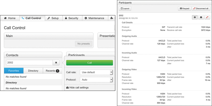
Figure 10-4 Dialing by Alias from the Web Interface of a DX80
Dialing out from the CLI requires a simple command. You open an SSH connection to the endpoint and then enter the following command:
xCommand dial number: alias
The alias should be the alias of the destination endpoint, such as 2002. Once the call connects, you can enter the following commands to view call connection status and to disconnect the call:
xStatus call
xCommand call disconnect
For more information about API commands on Cisco CE software-based Telepresence endpoints, use the following API reference guide: https://www.cisco.com/c/dam/en/us/td/docs/telepresence/endpoint/ce97/collaboration-endpoint-software-api-reference-guide-ce97.pdf.
Call by Directory
Another means of dialing out from an endpoint is to use the directory. A directory is a phonebook that the endpoint has access to but does not necessarily reside on the endpoint itself. Three different types of directories are available to endpoints: a local directory, a corporate directory, and a global directory.
The local directory is a collection of aliases that have been saved directly on the endpoint itself. The endpoint is the sole source of these directory entries; therefore, the endpoint will always contain these entries unless an administrator intentionally deleted them from the system. To add an entry into the local directory, a call attempt must be placed first. After a call has been attempted, whether the call successfully connected or not, locate the dialed alias in the Recents section of the call settings. When you select the entry, a list of options will appear. Select the Add to Local Contact option, and the entry will be added to the Favorites section, which is the local directory. Figure 10-5 illustrates how to add an alias to the local directory.
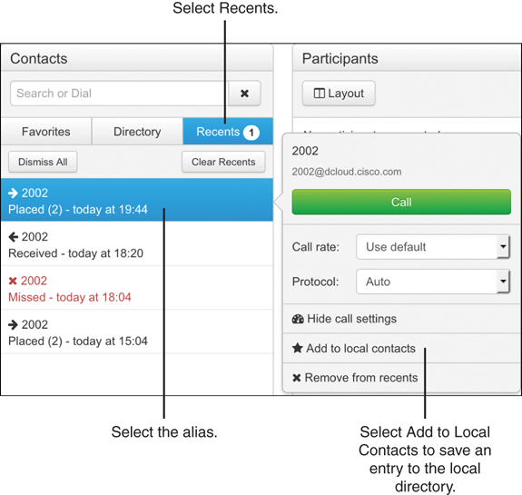
Figure 10-5 Adding an Alias to the Local Directory
The corporate directory is the most common directory used in Cisco collaboration. The corporate directory is a phonebook that an endpoint subscribes to when an entry needs to be looked up. These directories do not live on the endpoint itself; rather, they exist solely on the system designed to deliver the aliases when requested. Two systems in a Cisco collaboration solution are capable of delivering a corporate directory to Cisco endpoints. They are the Cisco Unified Communications Manager and the Cisco Telepresence Management Suite, or TMS. Because the focus of this book is on the Cisco Unified Communications Manager, we will not discuss TMS at this time. Endpoints have a finite amount of storage. In fact, a Cisco Collaboration Telepresence endpoint could hold only about 350 directory entries locally. Therefore, the idea of a corporate directory is to create a much larger depository of directory entries on a server built to sustain the greater load and make these entries available to the endpoint as users need the information. The endpoint must have the corporate directory location configured so that it knows where to send the subscription request when enquiring about an entry. When an endpoint registers to the Cisco Unified Communications Manager, the corporate directory address is included in the TFTP Get information sent to the endpoint. You can verify this setting is configured on the endpoint by navigating in the web interface to Setup > Configuration > Phonebook. The Type should be set to CUCM, and there may or may not be a URL configured.
The global directory is similar to a corporate directory, in that it originates on a server outside the endpoint itself. However, a global directory is pushed out to the endpoint, so the directory entries live on the endpoint just as the local directory entries live on the endpoint. Obviously, the limitation to this type of directory is the same limitation to the number of directory entries that can exist on a Cisco Telepresence endpoint. However, global directories can be used with a corporate directory. A limitation to the corporate directory is that if the endpoint loses the connection to the corporate directory, then the endpoint also loses those phonebook entries. However, important aliases can be pushed to an endpoint using a global directory, so that those phonebook entries will never be lost to the endpoint. Unfortunately, the Cisco Unified Communications Manager does not support a global directory. This is a function that only the Cisco TMS can provide.
Regardless of the directory choice, users can be dialed by the directory on the endpoint. You initiate the dialing behaviors the same way as described in the previous section. As you type letters in a name or numbers in a DN, entries will populate the screen. This is the nature of a corporate directory on the endpoint. When you see the name of the person or room you wish to call, select that entry and press the green Call button. Alternatively, you could select the Directory tab and see an alphabetized list of contacts from the combined directories that exist on your endpoint. Figure 10-6 illustrates the use of the directory feature for dialing from a Cisco DX80.
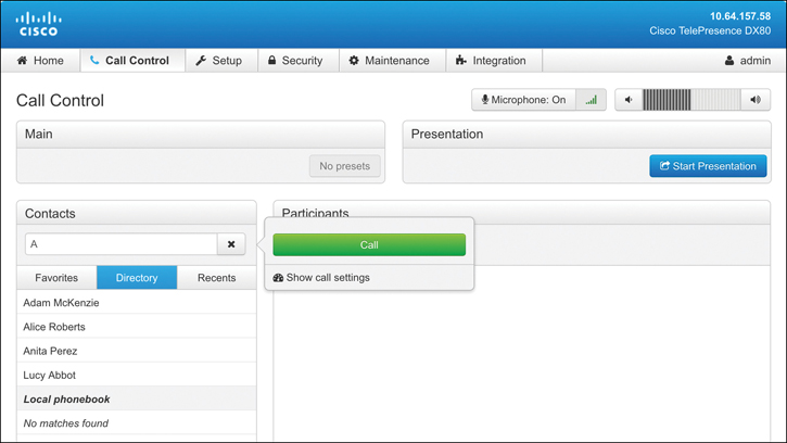
Figure 10-6 Dialing by Directory on a Cisco DX80
Multipoint Calling
Up to this point all the calling options discussed involve a point-to-point call. When you are connecting with a multipoint call, the options can be slightly different because different multipoint calling options exist. In a Cisco collaboration solution, three terms related to multipoint calling must be defined. They are multipoint, multisite, and multiway.
Multipoint is an industrywide term used to describe any call that involves three or more participants. Many conferencing products are available to host a multipoint call. Some of these products will be discussed momentarily. Multisite is a Cisco-specific term that came from the Tandberg acquisition. Multisite is the option key available on CE software-based endpoints that enables the endpoint to host a multipoint call. When multisite is used, no external conferencing resource is required. However, there are a lot of limitations to using the multisite option over an external conferencing resource. Depending on the endpoint being used for the multisite call, the number of participants allowed to join the call is limited. All participants in a multisite call must connect at a common bit rate, which is usually the lowest common bit rate among all the participants. Also, a lot more call options are available on a conferencing resource that are not available on the endpoint using multisite to host a call. The third term related to multipoint calling that needs to be defined is multiway. Like multisite, multiway is a Cisco-specific term that was adopted with the Tandberg merger. Multiway is simply call escalation from a point-to-point call to a multipoint call hosted on a Multipoint Conferencing Unit (MCU). Multiway is a function used by the Cisco VCS through a setting called the Conference Factory. It can be used only with a Cisco Telepresence MCU, which are end-of-life products.
A call escalation function is available through a Cisco Unified Communications Manager as well, although it is called ad hoc conferencing, not multiway. Ad hoc conferencing operates in the same capacity as multiway, allowing a point-to-point call to escalate to a multipoint call using an external conferencing resource to host the call. Any current Cisco conferencing resource can be used to support ad hoc calling on the Cisco Unified Communications Manager. Another conferencing option through the Cisco Unified Communications Manager is called rendezvous conferencing. Think of this conferencing type as an always-on conference space that can be joined at any time. Different settings must be configured on the Cisco Unified Communications Manager for ad hoc or rendezvous conferences, but both can exist at the same time. A third conferencing option is scheduled conferences, but these types of meetings cannot be configured from the Cisco Unified Communications Manager. Scheduled conferences must be configured through Cisco TMS.
Basically, three different Multipoint Conferencing Resources are available in a Cisco solution external to the multisite option on Cisco endpoints. Each of these conferencing options can be divided into an on-premises solution, a cloud-based solution, or a hybrid solution between the two. The on-premises solution Cisco offers is called the Cisco Meeting Server, or CMS. Licenses can be added to CMS for Personal Multiparty (PMP) or Shared Multiparty (SMP). PMP licenses are assigned to individual users, and no other party can join their personal space on CMS until the owner of the space has joined. SMP licenses are used to create a shared space into which any user can initiate a call. Therefore, it is recommended to protect SMP licensed meeting spaces on CMS with PINs in order to restrict who can utilize those resources. SMP licenses are also needed for scheduled meetings through TMS. When scheduled meetings are created, no participant can join the meeting until TMS initiates the conference. TMS can also create a private PIN, which participants must enter before joining the call.
Cloud-based meetings are hosted through the Cisco Webex Meeting Center. This is the same powerful tool that has been used for years to allow multipoint conferencing in the cloud. Participants can join via a Webex Meeting client, through a browser, using Webex Teams, or using a unified IP phone or Telepresence endpoint. Physical devices located on-premises, such as the Unified IP phones or Telepresence endpoints, require Expressway Core and Expressway Edge to be configured for firewall traversal to the Webex cloud before meetings can be joined from these devices. All the same tools that have traditionally been used with Webex Meetings are still available, such as high-quality voice and HD video communication, content sharing, polling, and annotation. Additionally, Cisco has added a few more enhancements to Webex Meeting Center, such as cognitive collaboration features.
Bandwidth limitations and network constrictions may negatively impact cloud-hosted meetings through the Webex Meetings solution. Therefore, Cisco has developed a new method to allow a hybrid service using both Webex Meetings and an on-premises conferencing service called the Video Mesh Node (VMN). The VMN is a virtual server that must be installed on-premises but operates in conjunction with Webex Meeting Center in the cloud. When Webex Meetings are scheduled, on-premises endpoints call into the VMN instead of calling into Webex directly. Then the VMN will send a single stream out to Webex with a composite of all the audio and video of the participants connected. Webex will send a composite of any participants connected directly to the cloud back to the VMN. In this manner, all participants are able to see and hear one another as if they were all connected to the same conferencing unit. The single stream sent between the VMN and Webex limits the bandwidth consumed across the edge network, and reduces the network constraints, creating a better user experience all around. Much more can be said for the hybrid conferencing solution, but that topic will have to be saved for another book.
One Button to Push (OBTP) and Scheduling Conferences
You should now have a basic understanding of the terms multipoint, multisite, and multiway, as well as ad hoc, rendezvous, and scheduled conferences. Furthermore, you should comprehend the differences between an on-premises conferencing solution compared to a cloud-based conferencing solution and a hybrid conferencing solution and be able to identify the different products used for each of these solutions. Bringing the subject back to the topic of dialing behaviors, each of these circumstances around multipoint communication can impact how participants are connected to meetings.
Similar to how participants call one another in a point-to-point call, participants can dial into a multipoint meeting if they know the associated alias. If multisite is used, this will be the alias of the endpoint hosting the call. If CMS or Webex are hosting the call, then the alias of the meeting space must be provided to the attendees before they will be able to dial in.
Multiway and ad hoc calls do not require the meeting ID to be known at all. One of the participants in a point-to-point call will place the second endpoint on hold while calling a third endpoint. With ad hoc, the Conference button must be selected to escalate the call. With multiway, the Join or Connect button must be selected to escalate the call. At that point the call control system, whether it is the Cisco Unified Communications Manager or the Expressway Core, is responsible for transferring the endpoints to the conferencing solution.
Scheduled multipoint calls can utilize any of the conferencing resources: multisite, CMS, or Webex with or without VMN. Many different circumstances influence how dialing behaviors will be impacted, but the following is simply a list of the possible ways through which calls can be connected. TMS can initiate calls from endpoints to the conferencing solution at a scheduled time. The user will not have to dial anything; the endpoint will just connect. TMS can also initiate calls from the conferencing solution out to the endpoint. In this case the user will need to answer the incoming call. A combination of these two options can also be configured, where TMS will automatically dial from some of the endpoints into the meetings and dial from the meeting out to other endpoints. TMS can start the meeting but not connect any participants to the meeting. The participants will need to know the alias to call into the meeting and dial in manually. A final, and more commonly used, option for connecting participants to meetings is the use of a tool call One Button to Push (OBTP).
One Button to Push is a communication option Cisco created prior to the Tandberg acquisition. After the merger was completed, Cisco quickly incorporated this feature into all the Tandberg products acquired. As new products have been developed, Cisco has ensured this highly sought-after feature is continually updated and supported across all of Cisco’s communications product portfolio. OBTP is a call connection option that functions only when meetings are scheduled. Although technology systems are very punctual, people are not always as prompt. If a scheduled meeting begins before the participants are ready to communicate, late participants entering the meeting room could be disruptive to others already connected to the meeting. The idea behind OBTP is that a Join button will appear on the endpoint scheduled for a meeting at the time the meeting is scheduled to begin. When the participants in the room of the endpoint are settled and ready to join the meeting, they select that Join button and are connected to the meeting at that time. There is no need know the meeting alias to join, and the endpoint will not be joined to the meeting before the participants are ready. It is no wonder this seamless solution is so widely adopted.
Content Sharing Options
Content sharing is a feature that allows media from a device external to the video endpoint to be displayed on or through the video endpoint. The content sharing feature has changed drastically over the last 30 years. Since video communication is a relatively new technology, the concept of sharing content over great distances had to be conceived and developed over time. The first standard that resembled content sharing was an old ITU standard that was part of the circuit-switched umbrella standard H.320. This standard was called T.150, and it was the Terminal Equipment and Protocols for Telematic Services, otherwise known as the Telewriting Terminal Equipment. This standard was originally drafted in 1983 and was later revised in 1993.
No other protocol was introduced for content sharing until 1999, when the Olivetti and Oracle Research Lab in Cambridge, UK, released an open-source protocol called virtual network computing, or VNC. VNC is a graphical desktop-sharing system that uses the Remote Frame Buffer (RFB) protocol to remotely control another computer. It transmits the keyboard and mouse events from one computer to another, relaying the graphical-screen updates back in the other direction, over a network. Although VNC can be used for remote desktop control, it was commonly used for content sharing over an IP call, since there was not a viable standard for content sharing yet.
This situation led to two proprietary protocols that were developed and released in 2000, specifically designed for content sharing. Tandberg released the DuoVideo protocol first, and later that year PictureTel released the People+Content protocol. Polycom acquired PictureTel in 2001 and assumed the continued development of People+Content. By 2002 Polycom was offering People+Content for any vendor to use royalty free.
In 2003, the ITU used both the Tandberg and Polycom content sharing protocols to develop a standard that could be used across all H.323 IP calls known as H.239. As SIP was growing in popularity for voice and video calls, a standard had to be drafted for content sharing over SIP as well. In 2006 the IETF drafted RFC 4582 for the Binary Floor Control Protocol (BFCP), which is used for content sharing over SIP. Today, H.239 and BFCP are the two predominant content sharing protocols used industrywide. However, Cisco has been working on other means of sharing content for audio-only participants while in a call. Who knows what other crazy idea might shape the future of content sharing standardizations!
Sharing Content
Content sources could be any devices capable of connecting to the video endpoint. Common content sources could be a dedicated desktop computer; personal laptop computer; smartphone; tablet; VHS, DVD, or Blu-ray player; or even a digital media player (DMP), such as an Apple TV or TV tuner. Content can be shared locally, meaning only in the same room as the video endpoint when not in a call, or content can be shared remotely through the video endpoint to the remote destination at the other end of the call. Most Cisco CE software-based endpoints will display the local content on the screen as soon as the content source is connected. Typically, this is through an HDMI, VGA, or DVI cable, but other connection systems are available although they will not be discussed in this book.
Sharing content while in a call is a manual process that must be executed with intention. This is not a difficult task to impose, but there is no possible way content can be shared by accident. If you were sharing content locally and someone were to call the endpoint you were sharing content through, the content sharing would cease the moment the call was answered. To share content while in a call, you must first select the Show PC button. This will only share the content locally. This feature gives the presenter a chance to see the content that will be presented prior to actually sharing the content. When you are ready to share the content, select the Share button, and the content will be sent in a video stream to the participants at the far end of the call. Tap the Stop Sharing button to end the content sharing session. If you disconnect the call before stopping the content sharing, you will still cease to share content as the call is terminated. If the other party in a call tries to share content while you are currently sharing content, your content sharing session will end, and that person’s content will be displayed as a replacement. The same behavior would occur if you were to try sharing content again while the far end was still sharing content.
Using Intelligent Proximity for Content Sharing
Earlier in the chapter, we discussed receiving content using the Proximity application. Any device running the Proximity application can receive content being shared; however, there is also a way to share content using the Proximity application. Content can be shared only if the Proximity application has been installed on a computer running Microsoft Windows or Apple Mac OS. Linux-based operating systems do not support the Proximity application, and smartphones and tablets do not support sharing content, only receiving content.
To install Proximity on your computer, navigate to www.proximity.cisco.com. Choose the appropriate operating system and download the executable file. When the download is complete, launch the installer, agree to the EULA, and begin using Proximity. Assuming the computer being used to share content through Intelligent Proximity meets the previous criteria, there are two ways to initiate the content sharing. Each way is slightly different depending on whether you are sharing content from a Windows PC or a Mac.
When you open the Proximity application on your Mac computer, a Proximity window will appear on the screen. In the app window is a Share Screen button. Tap this button to start sharing your screen. If you have two screens connected to your computer, select the Video System menu from the top left of the screen and choose Select Screen > <choose screen>. To stop sharing, bring the app back to the front of the screen and click the Stop Sharing button. When Proximity is installed, a Proximity icon also appears in the top bar on the screen. If you click this bar, you will see all the different menu options available. Go to the Select Screen menu to choose the appropriate display to present from. Then choose the Share Screen menu option to start sharing content. Choose Stop Sharing when you are finished sharing.
There are two ways to share content from a Microsoft Windows computer as well. Sharing content using the Proximity app on a Windows computer is basically the same as sharing content through the app on a Mac computer. Alternatively, you could press Alt+F12 to start sharing content. Proximity must be running and connected to the endpoint before content can be shared through the application. If another user is sharing content and you start sharing from the Proximity app on your computer, your shared content will override that user’s content, and they will stop sharing. The same would be true if someone else started sharing content while you were sharing. Figure 10-7 illustrates the two ways to share content through the Proximity application from a Mac.

Figure 10-7 Content Sharing from a Mac Using Proximity
Other Features
Many calling features available through CE software-based endpoints provide administrators with granular control over the video Telepresence environment. There are more features than what is covered in the sections that follow; however, the following examples are some of the more commonly used settings on these endpoints. None of these settings can be configured from the user interface. They must all be configured from the web interface or the CLI. When an administrator accesses the Setup > Configuration menus of a CE software-based endpoint through the web interface, all of the following settings can be configured by selecting the appropriate menu in the left column. The sections that follow cover those menu options in order from the top down. Encryption Mode, AutoAnswer, and Far-End Camera Control are all features listed under Setup > Configuration > Conference.
Audio Settings
Some of the audio settings on certain CE software-based endpoints are more extensive than the audio settings on other endpoints. For example, the Cisco Telepresence DX80 endpoint does not have as many audio inputs and outputs as the Cisco Webex Room Kit Pro endpoint, which was built for custom integrator solutions. Therefore, the audio menu options on a Cisco Webex Room Kit Pro are much more extensive than the audio menu options on the Cisco Telepresence DX80. Depending on what endpoints you are planning to deploy and support, you should spend some time in the deployment guides to familiarize yourself with the different audio options available. However, all CE software-based endpoints share a few common audio settings.
Basic audio settings include audio output settings, such as DefaultVolume, and input settings, such as Input MicrophoneMode, which sets the microphone pickup area, or Microphone Mute Enabled. The DefaultVolume setting comes preset to 50 and can be changed to any value between 0 and 100. The Input MicrophoneMode is preset to Wide so that more participants can be accommodated around a single microphone, but it can be changed to Focused if the room is designed for fewer participants. The Microphone Mute Enabled setting can be set to True or InCallOnly. This setting does not mute the microphone; rather it enables the user to mute the microphone. Therefore, this setting can be configured to always allow the microphone to be muted, or it can prevent the microphone from being muted unless there is an active call in session. Some people like to mute the microphone prior to placing a call; therefore, the default value of True should be left unchanged.
Another section of audio settings that are consistent among all CE software-based endpoints is the SoundAndAlerts settings. The two settings that can be configured in this section are RingTone and RingVolume. RingTone is the audio tone a user will hear when an incoming call is being attempted. The following 12 different ringtones are available on Cisco Telepresence endpoints:
Sunrise (default value)
Mischief
Ripples
Reflections
Vibes
Delight
Evolve
Playful
Ascent
Calculation
Mellow
Ringer
RingVolume is different from DefaultVolume, in that it only impacts how loud the ringing signal will alert. DefaultVolume impacts the actual audio of the far-end participants as their dulcet tones are projected from the system speakers. Much like DefaultVolume, RingVolume defaults at 50 and can be modified between 0 and 100. Figure 10-8 illustrates these audio settings from a Cisco Telepresence DX80 endpoint.
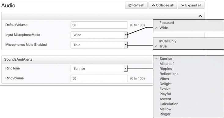
Figure 10-8 Audio Settings on a Cisco Telepresence DX80
Encryption Mode
Encryption Mode, which is a setting located under the Conference menu, has to do with call encryption during call setup. Call encryption can occur for both H.323 and SIP calls, but the encryption they use is slightly different. Both use TLS for TCP and UDP packet encryption. However, H.323 supports 56-bit DES encryption or 128-bit AES encryption. SIP supports AES 128- or 256-bit encryption. Also, the means by which H.323 and SIP perform the handshake for secure transmission is different. Because so many different encryption options exist for the two call control protocols, only three settings on CE software-based endpoints revolve around Encryption Mode: BestEffort, On, and Off.
BestEffort is the default setting. The idea behind BestEffort is that the endpoint will try to encrypt when the call is first set up. If the far-end endpoint does not support the same encryption algorithms, or if the far-end endpoint has encryption disabled, then the call will continue as an unencrypted call. When the EncryptionMode is set to on, the call can proceed only if the destination endpoint is also configured to support call encryption and the two algorithms match. Otherwise, the call will fail. The same is true when the Encryption Mode is set to Off. The endpoint will never try to encrypt, so if the far-end endpoint requires encryption, then the call attempt will fail.
AutoAnswer
The second section located under the Conference menu is called AutoAnswer. This feature performs exactly as the name implies. When an endpoint is called and the AutoAnswer feature is enabled, the endpoint will answer the call on its own volition without any human interaction. This capability might seem scary to some people because with AutoAnswer enabled, a user may be caught unaware during a call. You should understand that this feature is disabled by default, so you would have to intentionally enable it before calls could be answered automatically. However, there was a time when AutoAnswer was the norm, and a lot of people had home video systems. People have been caught sleeping, coming out of the shower, and entrenched in many other precarious situations.
The idea behind why this feature exists came out of a time when the conference meeting bridge would dial out to all the scheduled endpoints at the time the meeting was supposed to start. Whether the participants were in attendance at their assigned location or not, the endpoint needed to answer the call to ensure the call connected at the scheduled time. Then Cisco released the OBTP feature discussed previously in this chapter, and just like that, the AutoAnswer feature became much less commonly used. If the AutoAnswer feature is going to be used, some best practice tips need to be taken into consideration. First, you should enable this feature only on meeting room endpoints. Do not enable the feature on personal video endpoints, and definitely do not enable this feature on home video devices. Second, if AutoAnswer is enabled, it is a good idea to enable the Mute on Answer feature. This way, the call will connect as it should, but while people are still settling in the meeting room, the noise will not be disturbing to other participants in the call at remote locations.
The AutoAnswer section consists of three settings: Delay, Mode, and Mute. Delay is measured in seconds and determines the time duration the incoming call should ring before the endpoint will answer the call automatically. The default value is 1, and this setting can be set to any number between 0 and 50. Mode is the setting used to enable the AutoAnswer feature. The default value is Off, and this setting can be changed to On. Mute can be set to Off, which is the default value, or On. When this feature is enabled along with Mode, the endpoint will mute the microphone(s) at the time the call is answered. It is strongly recommended to enable the Mute feature if AutoAnswer is enabled. Figure 10-9 illustrates the AutoAnswer settings in a DX80 endpoint.

Figure 10-9 AutoAnswer Feature Settings on a DX80
Far-End Camera Control (FECC)
A third setting located under the Conference menu that is commonly used is the Far-End Camera Control (FECC) settings. FECC is a setting that allows the camera on your video endpoint to be controlled remotely by another endpoint while in a call. Obviously, camera control can occur only if the camera on the endpoint is an auto PTZ camera, such as the Cisco Precision 60 camera. The camera built into the DX80 endpoint is a manual tilt and zoom camera, with no panning capability. Therefore, enabling FECC on this endpoint would be pointless. The same would be true for the Webex Room Kit series endpoints because the cameras integrated into those endpoints operate differently than the traditional auto PTZ cameras. The capability to control a camera on the far end of a call does not require any setting to be enabled. This capability is built into all Cisco Telepresence endpoints automatically and is always available.
To configure FECC on a Cisco CE software-based endpoint from Setup > Configuration > Conference, scroll down to the bottom of the page and look for the FarEndControl section. The Mode setting should be set to On by default. This means that FECC is automatically enabled on the endpoint. To disable FECC, change the Mode to Off. Another setting under the FarEndControl section, called SignalCapability, can be set to On (default) or Off. The standard for FECC is H.224, so this setting enables or disables the use of H.224 for FECC. Because the SignalCapability setting performs the same essential function as Mode, it should be configured using the same setting as Mode for the desired service of FECC. In other words, if Mode is set to On, then SignalCapability should be set to On. If Mode is set to Off, then SignalCapability should be set to Off.
Phonebooks
The earlier “Call by Directory” section discussed the differences between the local directory, corporate directory, and global directory. Local directories are created on the endpoint itself, and global directories are initiated from the Phonebook service; therefore, no settings need to be configured on the endpoint to receive global directories. However, corporate directories require the endpoint to initiate a Subscription message to the phonebook service for each individual phonebook lookup in order to receive entries in reply. This allows the phonebook service to supply only listings based on the characters or numbers that have been entered. You can configure subscription information on the Phonebook menu on Cisco Telepresence endpoints so that the endpoints know where to send the Subscription message. When an endpoint registers to the Cisco Unified Communications Manager, the Phonebook information is automatically provisioned on the endpoint, so no settings need to be configured. However, when the Cisco TMS services are used for Phonebook management, these settings may need to be changed.
There are three settings under the Phonebook > Server 1 section. The ID setting allows a name to be assigned to the phonebook. By default, no name is associated with the phonebook, and the phonebook will continue to function as normal if no name is assigned.
The Type setting allows an administrator to determine from where the phonebook source will come. The default value for this setting is Off, but it can be configured as any of the following:
CUCM: Use this setting if the Cisco Unified Communications Manager is the source of the corporate directory. When the endpoint registers to the Cisco Unified Communications Manager, this setting will change automatically, and no other settings have to be configured on the endpoint.
Spark: Use this setting if the Webex Control Hub is the source of the corporate directory. When the endpoint registers to the Webex Control Hub, this setting will change automatically, and no other settings have to be configured on the endpoint.
TMS: Use this setting if Cisco TMS is the source of the corporate directory.
VCS: Neither the Cisco VCS nor the Expressway can be the source of the corporate directory. However, if the endpoint is registered to one of these products, TMS can be the source for the phonebook. Therefore, Type can be set to VCS or TMS.
The third setting under Phonebook > Server 1 is the URL setting. In some instances, a URL address to the server providing phonebook services is required. This setting will never be required when Type > Spark is selected, will only occasionally be required when Type > CUCM is selected, and will always be required when Type > TMS or Type > VCS is selected. An example of the URL that may be used when the Type is set to CUCM could be as follows:
https://<cucm-host-name>:8443/cucm-uds/users
An example of the URL that may be used when the Type is set to TMS or VCS could be as follows:
https://<tms-host-name>/tms/public/external/phonebook/phonebookservice.asmx
In both examples, the portion of the URL that is in bold could be the IP address or DNS A-record of the server the name references, TMS or CUCM. Notice that within both URLs specific directories are referenced. You could use these URLs in any production environment by simply replacing the bold portion with your specific server address information. Figure 10-10 illustrates the Phonebook settings on a Cisco Telepresence endpoint.

Figure 10-10 Phonebook Settings on a Cisco Telepresence Endpoint
Video Settings
The last group of settings that will be discussed in this chapter is the video settings. Under the Setup > Configuration section, Video is at the bottom of the menus in the left column. Much the same as audio settings, video settings may vary based on the endpoint’s capabilities. Different endpoints have more or fewer video inputs and video outputs. Therefore, there may be more or fewer menu options based on the number of inputs and outputs. However, many common settings are consistent among all Cisco Telepresence endpoints regardless of the endpoint being used. The Video menu is divided into the following six sections:
Top Main Video section
DefaultLayoutFamily
Input
Output
Presentation
Selfview
The top main video section does not have a section title. The settings listed in this section are the main functional settings related to the endpoint. Some of the settings listed here include Active Speaker DefaultPIPPosition. PIP stands for Picture-in-Picture and refers to a video screen layout where a smaller video pane can exist within a larger video pane. The configuration options for this setting pertain to the positioning of the PIP, and they affect the layout only when a call is in session that uses a layout with a PIP overlay. The options for this setting can be any of the following:
CenterLeft
CenterRight
Current
LowerLeft
LowerRight
UpperCenter
UpperLeft
UpperRight
The next setting in the first section is the DefaultMainSource. This setting determines which display will be the main video display when a call is in session. Some of the Cisco CE software-based endpoints support two or more displays. In these environments the default main source displays the incoming video of the far-end participants, while the second display is used for content presentation only. When the endpoint is used for local meetings, both displays can support content sharing. The next setting in this section is called Monitors. Similar to the DefaultMainSource setting, the Monitors setting determines how many monitors are currently being supported from this endpoint.
The next section under the Video menu is the DefaultLayoutFamily. These settings pertain only to multipoint calls that use the multisite feature on the endpoint. Five different layouts are supported with the multisite feature, and they can be configured differently for Local and Remote. Local is the layout that participants at this endpoint will view during a call, and Remote is the layout that will be presented to other participants connected to the call. The five layouts supported using the multisite feature are as follows:
Auto: The default layout family, as given by the local layout database, will be used as the remote layout.
Equal: All video participants will have equal-sized panes as long as there is enough space on the screen.
Overlay: The active speaker, or the presentation if present, will be shown in full screen, while the other participants will be small PIPs. Transitions between active speakers are voice switched.
Prominent: The active speaker, or the presentation if present, will be a larger picture, while the other participants will be smaller pictures. Transitions between active speakers are voice switched.
Single: The active speaker, or the presentation if present, will be shown in full screen. The other participants will not be shown at all. Transitions between active speakers are voice switched.
The third Video section is the Input section. These settings are the controls for all of the video input ports on the endpoint itself, and therefore, there could be more or fewer settings listed based on the type of endpoint. Video input settings control devices such as cameras or content devices. Some endpoints support daisychaining multiple cameras together in a single room environment, so an administrator may want to assign a camera ID to each camera in the room and provide a name for the cameras, such as Rear Camera or Whiteboard Camera. Content sources could be an in-room computer, table-connected laptop, DVD or Blu-ray player, document camera, Apple TV, or any other device through which content can be shared. Because more than one content source can be connected to the endpoint at a time, the administrator may be inclined to name the content sources as well. Figure 10-11 illustrates the first three video sections that have been mentioned up to this point.
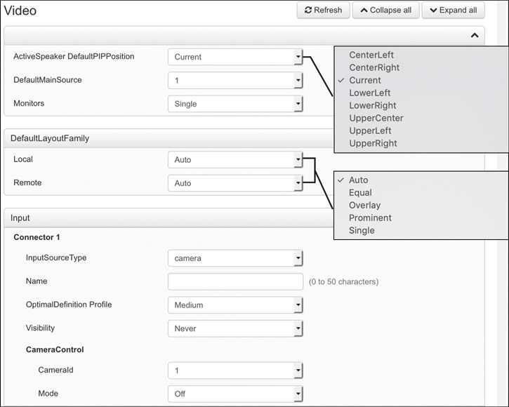
Figure 10-11 Main, Layout, and Input Video Menu Sections
Just as with the Video > Input section, the Video > Output section will have an equal number of Connector settings for configuration as the number of physical video output ports on the endpoint itself. So, the number of settings in this section could be more or fewer depending on the endpoint being used. Additionally, the setting options under each connector may differ based on the type of connection supported. Video outputs are the connector ports that the displays connect to on the endpoint. Some of the different settings you may encounter in the Output section on the endpoint include the following:
Brightness: This setting defines the brightness level.
Resolution: This setting defines the resolution and refresh rate for the connected screen. When Auto resolution is selected, the endpoint will automatically try to set the optimal resolution based on negotiation with the connected monitor.
Whitebalance Level: This setting defines the camera’s white balance level.
CEC Mode: This video output (HDMI) supports Consumer Electronics Control (CEC). When this setting is On, the system will use CEC to set the screen in standby mode when the endpoint itself enters standby. Likewise, the system will wake up the screen when the system itself wakes up from standby mode. Note that different manufacturers use different marketing names for CEC, such as Anynet+ (Samsung); Aquos Link (Sharp); BRAVIA Sync (Sony); HDMI-CEC (Hitachi); Kuro Link (Pioneer); CE-Link and Regza Link (Toshiba); RIHD (Onkyo); HDAVI Control, EZ-Sync, VIERA Link (Panasonic); EasyLink (Philips); and NetCommand for HDMI (Mitsubishi).
OverscanLevel: Some monitors may not present the entire image that they receive. This means that the outer parts of the image that is sent from the video system may be cut off when displayed on the monitor. You can use this setting to instruct the video system not to use the outer part of the available frame. This part might be cut off by the monitor. Both the video and messages onscreen will be scaled in this case.
RGBQuantizationRange: Devices connected to an HDMI output should follow the rules for RGB video quantization range defined in CEA-861. Unfortunately, some devices do not follow the standard, and this configuration may be used to override the settings to get a perfect image with any display. Most HDMI displays expect the full quantization range.
Auto: The RGB quantization range is automatically selected based on the RGB Quantization Range bits (Q0, Q1) in the AVI infoframe. If no AVI infoframe is available, the RGB quantization range is selected based on the video format according to CEA-861-E.
Full: Full quantization range. The RGB quantization range includes all code values (0–255). This is defined in CEA-861-E.
Limited: Limited quantization range. This RGB quantization range excludes some code values at the extremes (16–235). This is defined in CEA-861-E.
Location > HorizontalOffset/VerticalOffset: These two settings are associated with each video output, and they are used to signal the relative position of the displays that are connected to these outputs. HorizontalOffset = 0 and VerticalOffset = 0 indicates that the display is positioned in the center, both horizontally and vertically. A negative horizontal offset indicates that the monitor is left of center, and a positive horizontal offset indicates that the monitor is right of center. A negative vertical offset indicates that the monitor is below center, and a positive vertical offset indicates that the monitor is above center. The magnitude of the offset indicates how far the display is from center (relative to other displays).
The next section is the Presentation section, and two settings here can be configured. The DefaultPIPPosition is the same setting as the ActiveSpeaker DefaultPIPPosition setting discussed earlier. All of the configuration options are the same, except that this setting pertains specifically and exclusively to content being shared. Again, if the layout choice does not use PIP, this setting will not apply. The DefaultSource setting allows an administrator to specify the video input that will act as the primary source for content sharing. This setting will always be a number value and will be based on the video inputs the endpoint supports. For example, the DX80 has only one video input dedicated to content sharing, and that port is hard-coded as video input 2. Therefore, the DefaultSource setting for presentation will always be 2, and this setting cannot be changed. However, a Cisco Webex Room Kit Pro has several video input ports, so this setting would be configurable from the web interface.
The Selfview section pertains to how the self-view window will appear when this feature is enabled. Self-view can be enabled, disabled, and positioned from the user interface, but the more advanced settings must be configured from the web interface or the CLI. The two subsections in the Selfview section are called Default and OnCall. The Default subsection contains the following parameters:
FullScreenMode: This setting defines whether self-view should be shown in full-screen or as a small PIP after a call. The setting takes effect only when self-view is switched on.
Off: Self-view will be shown as a PiP.
Current: The size of the self-view picture will be kept unchanged when leaving a call; that is, if it was a PiP during the call, it will remain a PiP after the call; if it was full-screen during the call, it will remain full-screen after the call.
On: The self-view picture will be shown in full-screen.
Mode: This setting defines whether self-view should be displayed onscreen after a call. The position and size of the self-view window are determined by the Video > Selfview > Default > PIPPosition and the Video > Selfview > Default > FullscreenMode settings, respectively.
Off: Self-view is switched off when leaving a call.
Current: Self-view is left as is; that is, if it was on during the call, it will remain on after the call; if it was off during the call, it will remain off after the call.
On: Self-view is switched on when leaving a call.
OnMonitorRole: This setting defines which screen output to display the main video source for self-view after a call. The value reflects the monitor roles set for the different outputs in the Video > Output > Connector > [n] > MonitorRole setting. The setting applies both when self-view is displayed in full-screen, and when it is displayed as a PIP.
Current: When leaving a call, the self-view picture will be retained on the same output as it was during the call.
First: The self-view picture will be shown on outputs with the Video > Output > Connector > [n] > MonitorRole set to First.
Second: The self-view picture will be shown on outputs with the Video > Output > Connector > [n] > MonitorRole set to Second.
Third: The self-view picture will be shown on outputs with the Video > Output > Connector > [n] > MonitorRole set to Third.
PIPPosition: This setting defines the position onscreen of the small self-view PIP after a call. The setting takes effect only when self-view is switched on and full-screen view is switched off. All of the configuration options are the same as the ActiveSpeaker DefaultPIPPosition options, except that this setting pertains specifically and exclusively to self-view.
The OnCall subsection contains two parameters: Duration and Mode. OnCall > Mode is used to switch on self-view for a short while when setting up a call. The Video > Selfview > OnCall > Duration setting determines how long self-view will remain on at the beginning of a call. This setting applies when self-view in general is switched off. Duration defaults to 10 and can be set to any value between 1 and 60. Each numeric value represents one second. If Mode is set to On, then self-view will show momentarily at the beginning of a call. If Mode is set to Off, then self-view will not show at all during any point of the call. Figure 10-12 illustrates the video output settings, presentation settings, and selfview settings on a Cisco Telepresence endpoint.
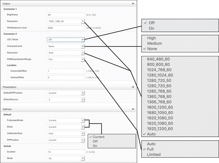
Figure 10-12 Output, Presentation, and Selfview Video Menu Sections
Exam Preparation Tasks
As mentioned in the section “How to Use This Book” in the Introduction, you have a couple of choices for exam preparation: the exercises here, Chapter 32, “Final Preparation,” and the exam simulation questions in the Pearson Test Prep Software Online.
Review All Key Topics
Review the most important topics in this chapter, noted with the Key Topics icon in the outer margin of the page. Table 10-2 lists a reference of these key topics and the page numbers on which each is found.
Table 10-2 Key Topics for Chapter 10
Key Topic Element |
Description |
Page Number |
|---|---|---|
List |
Three Ways to Place or Answer a Call on CE Endpoint |
235 |
Paragraph |
Three Control Mechanisms for CE Endpoints |
236 |
Paragraph |
Calling from CE Endpoint Using the On-Screen Display (OSD) |
237 |
Paragraph |
Reasons for Dialing from Web Interface or CLI |
238 |
Paragraph |
Three Types of Directories |
239 |
Paragraph |
Two Systems That Deliver Corporate Directories |
240 |
Paragraph |
Define Multipoint, Multisite, and Multiway |
241 |
Paragraph |
Explain CMS as the On-Premises Conferencing Solution |
242 |
Paragraph |
Explain Webex Meeting Center as the Cloud-Based Conferencing Solution |
242 |
Paragraph |
Explain VMN as the Hybrid Conferencing Solution |
242 |
Paragraph |
Call Connections Through Scheduled Multipoint Meetings |
243 |
Paragraph |
OBTP |
244 |
Paragraph |
Define VNC |
244 |
Paragraph |
How to Share Content while in a Call |
245 |
Paragraph |
How to Share Content Using Proximity App |
245 |
Section |
Encryption Mode |
248 |
Paragraph |
AutoAnswer Best Practices |
249 |
Paragraph |
Explain FECC |
249 |
Paragraph |
Corporate Directory Settings Explained |
250 |
List |
Active Speaker DefaultPIPPosition Settings |
252 |
List |
Five Layouts Supported by Multisite |
252 |
Define Key Terms
Define the following key terms from this chapter and check your answers in the glossary:
Q&A
The answers to these questions appear in Appendix A. For more practice with exam format questions, use the Pearson Test Prep Software Online.
1. List the five control mechanisms that allow users and administrators to interact with Cisco CE software-based endpoints.
2. List five devices that can be used as a content resource on Cisco CE software-based endpoints.
3. What are the four Type options for a phonebook source on the Cisco Telepresence endpoint?
4. List and describe the five multisite layouts supported on the Cisco Telepresence endpoint.