
Chapter 22
Cisco IOS XE Gateway and Media Resources
This chapter covers the following topics:
DTMF: This topic will examine the complexity behind DTMF due to its many purposes and how different protocols allow DTMF communication across the network. This topic will also examine how MTPs can be used to overcome the issues that surround DTMF.
CUCM Call-Routing Options: This topic will identify the four different routing options available through the Cisco Unified Communications Manager and how to configure the three main routing options: MGCP gateways, H.323 gateways, and SIP trunks.
Cisco IOS XE Gateway Settings for ISDN Routing: This topic will explain different settings that must be configured on Cisco IOS XE routers to support IP to ISDN routing and vice versa. These settings include codec preference lists, dial peers, and voice translation rules and profiles.
Configure and Troubleshoot ISDN BRI: This topic will identify the commands used to configure Cisco IOS XE routers equipped with ISDN BRI controller cards. Additional commands covered in this section can be used to verify and troubleshoot issues related to the BRI interfaces.
Configure and Troubleshoot ISDN PRI: This topic will identify the commands used to configure Cisco IOS XE routers equipped with ISDN PRI controller cards. Additional commands covered in this section can be used to verify and troubleshoot issues related to the PRI interfaces.
Part of what makes collaboration such a hard technology to understand has to do with the fact that a collaboration engineer must be knowledgeable in every architecture of IT. The collaboration engineer must know audio and video fundamentals, networking, security, data center, cloud, and even programmability. This chapter will focus on some of the networking aspects that relate to collaboration. Cisco IOS XE routers are capable of supporting ISDN channel controller cards and use DSPs for IP-to-ISDN conversion. Many settings must be configured on these routers to support this capability. Topics discussed in this chapter include the following:
DTMF
CUCM Call-Routing Options
MGCP Gateway
H.323 Gateway
SIP Trunk
Cisco IOS XE Gateway Settings for ISDN Routing
Codec Preference List
Dial Peers
Voice Translation Rules and Profiles
Configure and Troubleshoot ISDN BRI
Configure and Troubleshoot ISDN PRI
This chapter covers the following objectives from the Cisco Collaboration Core Technologies v1.0 (CLCOR 350-801) exam:
1.2 Describe the purpose of Edge devices in the Cisco Collaboration architecture such as Expressway and Cisco Unified Border Element
1.3 Configure these network components to support Cisco Collaboration solutions
3.1 Configure these voice gateway elements
3.1.a DTMF
3.1.b Voice translation rules and profiles
3.1.c Codec preference list
3.1.d Dial peers
3.2 Configure ISDN PRI/BRI
3.3 Troubleshoot ISDN PRI/BRI
3.4 Configure and verify the MGCP
“Do I Know This Already?” Quiz
The “Do I Know This Already?” quiz allows you to assess whether you should read this entire chapter thoroughly or jump to the “Exam Preparation Tasks” section. If you are in doubt about your answers to these questions or your own assessment of your knowledge of the topics, read the entire chapter. Table 22-1 lists the major headings in this chapter and their corresponding “Do I Know This Already?” quiz questions. You can find the answers in Appendix A, “Answers to the ‘Do I Know This Already?’ Quizzes.”
Table 22-1 “Do I Know This Already?” Section-to-Question Mapping
Foundation Topics Section |
Questions |
|---|---|
DTMF |
1 |
CUCM Call-Routing Options |
2–5 |
Cisco IOS XE Gateway Settings for ISDN Routing |
6–9 |
Configure and Troubleshoot ISDN BRI |
10 |
Configure and Troubleshoot ISDN PRI |
11 |
Caution
The goal of self-assessment is to gauge your mastery of the topics in this chapter. If you do not know the answer to a question or are only partially sure of the answer, you should mark that question as wrong for purposes of the self-assessment. Giving yourself credit for an answer you correctly guess skews your self-assessment results and might provide you with a false sense of security.
1. Which of the following is an in-band method of sending DTMF from one endpoint to another after the call media has been established?
KPML
NTE
UN
H.245 Signal, H.245 Alphanumeric
2. Which of the following gateway types supports BRI ISDN connections, but not PRI?
SCCP
MGCP
SIP
H.323
3. After an MGCP gateway has been added to the Cisco Unified Communications Manager and saved, what is the next step?
Reset the MGCP Gateway.
In the Configured Slots, VICs and Endpoints area, configure the network module.
Configure the BRI port interface for the MGCP gateway.
No further steps are needed.
4. Which of the following statements about H.323 gateways is true?
If your deployment includes H.323 gatekeepers, you can also add an H.323 gateway by setting up a gatekeeper-controlled H.225 trunk.
H.323 gateways can be configured in the Cisco Unified Communications Manager for a non-gatekeeper H.323 deployment or an H.323 gatekeeper deployment.
H.323 gateways can be configured in the Cisco Unified Communications Manager for an H.323 gatekeeper deployment.
An H.225 trunk can be configured in the Cisco Unified Communications Manager for a non-gatekeeper H.323 deployment.
5. Before a SIP trunk is configured in the CUCM toward an IOS XE router for ISDN access, what other setting should be configured first?
SIP normalization script
Route pattern
SIP phone security profile
SIP profile
6. Which Cisco router model uses a single-port 30-channel T1/E1 high-density voice port adapter?
Cisco 2600 series
Cisco 3600 series
Cisco 7200 series
MC3810
7. What command should be used to identify the video codec H.261 as the preferred codec?
codec preference 1 h261
voice class codec h261
voice class codec 1 followed by video codec h261
Video codecs cannot be set in an IOS XE router.
8. When the router matches the information elements in the setup message with the dial-peer attributes to select an inbound dial peer, the router will match these items in a specific order. Which of the following determines the first thing that will be searched?
Called number (DNIS) with the incoming called-number command
Calling number (ANI) with the answer-address command
Calling number (ANI) with the destination-pattern command
Voice-port (associated with the incoming call setup request) with configured dial-peer port (applicable for inbound POTS call legs)
Dial peer 0 (pid:0)
9. Which of the following voice translation rules will match 5551001 and change it to 9195551001?
/(555)(….)/ /91912)
/5551001/ /919/
/^555..../ /91912/
/^$/ /9191/
10. Which command will display information about the physical attributes of the BRI B- and D-channels?
show controllers bri <number> or show controllers bri <slot/port>
show isdn {active [serial-number] | history [serial-number]}
show isdn status
show interface bri
11. Which command will display the version of software residing on the voice feature card in the specified slot?
show vfc slot version
show isdn status
show isdn {active [serial-number] | history [serial-number]}
show voice port {<slot/port> | summary}
Foundation Topics
DTMF
A media resource is a software- or hardware-based entity that performs media-processing functions on the data streams to which it is connected. Media-processing functions include mixing multiple streams to create one output stream (conferencing), passing the stream from one connection to another (media termination point), converting the data stream from one compression type to another (transcoding), streaming music to callers on hold (music on hold), using echo cancellation, signaling, performing voice termination from a TDM circuit (coding/decoding), packetizing a stream, streaming audio (annunciation), and so forth. The software-based resources are provided by the Cisco Unified Communications Manager IP Voice Media Streaming Service (IP VMS). Digital signal processor (DSP) cards provide both software- and hardware-based resources.
A media termination point (MTP) is a media resource that allows the passing of a stream from one discontiguous connection to another. MTPs can be used for repacketization of a stream, dual-tone multifrequency (DTMF) conversion, bridging between IPv4 and IPv6, and other protocol-specific connections involving SIP and H.323.
Dual-tone multifrequency signaling is an in-band communications system that telephone companies have used for many years, which allows end users to communicate by pressing keys on their phone. DTMF can be used during call setup, such as dialing a phone number, or during a call to navigate a menu selection. If you were to call your bank, you would probably be greeted with an automated system that guided you through a menu of options, which you could choose by pressing a numeric key on your phone. Unfortunately, DTMF used for call setup is processed differently from DTMF used during a call for menu selection. When sending DTMF during a call, you can use several different methods depending on what calling protocol, phone models, and call control systems are being used. Two endpoints in a call may not support the same method, and an MTP may be needed to convert DTMF signaling between endpoints. One MTP resource is needed per call; therefore, it is important to plan out the resources needed before deploying MTPs in a production environment. Table 22-2 outlines the different methods that can be used to relay DTMF between endpoints.
Table 22-2 DTMF Relay Methods
DTMF Method |
Description |
|---|---|
Named Telephony Events (RFC 2833) |
Named Telephony Events (NTEs) are a method of sending DTMF from one endpoint to another after the call media has been established. The tones are sent as packet data using the already-established RTP stream and are distinguished from the audio by the RTP payload type field. |
Key Press Markup Language (RFC 4730) |
Unlike NTEs, which is an in-band method of sending DTMF, Key Press Markup Language (KPML) uses the signaling channel (out-of-band, or OOB) to send SIP messages containing the DTMF digits. KPML procedures use a SIP SUBSCRIBE message to register for DTMF digits. The digits themselves are delivered in NOTIFY messages containing an XML-encoded body. |
Unsolicited Notify (UN) |
UN procedures are used primarily by Cisco IOS SIP gateways to transport DTMF digits using SIP NOTIFY messages. Unlike KPML, these NOTIFY messages are unsolicited, and there is no prior registration to receive these messages using a SIP SUBSCRIBE message. Also, unlike KPML, which has an XML-encoded body, the message body in these NOTIFY messages is a 10-character encoded digit, volume, and duration, describing the DTMF event. Similar to KPML, UN messages are OOB. |
H.245 Signal, H.245 Alphanumeric |
H.245 is the media control protocol used in H.323 networks. In addition to its use in negotiating media characteristics, H.245 also provides a channel for DTMF transport. H.245 utilizes the signaling channel and, therefore, provides an OOB way to send DTMF digits. The Signal method carries more information about the DTMF event (such as its actual duration) than does Alphanumeric. |
Cisco Proprietary RTP |
This method sends DTMF digits in-band in the same stream as RTP packets. However, the DTMF packets are encoded differently from the media packets and use a different payload type. This method is not supported by CUCM but is supported on Cisco IOS gateways. |
Skinny Client Control Protocol (SCCP) |
SCCP is used by CUCM for controlling the various SCCP-based devices registered to it. SCCP defines OOB messages that transport DTMF digits between CUCM and the controlled device. |
When endpoints are registered to the same Cisco Unified Communications Manager cluster and are in a call together, some rules will apply regarding the use of MTPs for DTMF relay. Calls between two non-SIP endpoints do not require an MTP. Calls between two Cisco SIP endpoints do not require an MTP. However, a call between a SIP endpoint and a non-SIP endpoint may require an MTP.
Trunks and gateways through the Cisco Unified Communications Manager may present unique situations that require an MTP. SIP trunks are used to establish communication between SIP user agents. This could be another Cisco Unified Communications Manager, a Cisco Expressway Core, a Cisco IOS XE router, or some other similar device. Before we can provide an explanation as to when an MTP needs to be used, we need to explain some basic SIP protocols and behaviors.
If two endpoints were in a SIP call through the same Cisco Unified Communications Manager cluster, the call setup could use Early Offer or Delayed Offer. In an Early Offer, the capabilities exchange and UDP port identification are sent in the initial Invite message of the SIP call setup. This information is sent using a protocol called Session Description Protocol (SDP). With Early Offer, the calling endpoint will always initiate the SDP negotiation. Delayed Offer will not send SDP information until a “200 OK” response to the initial Invite message has been received. With Delayed Offer, the called endpoint will initiate the SDP negotiation when it sends the “200 OK” response to the initial invite message. In either case, an MTP is not needed to support these calls.
Conversely, when a SIP call is sent over a SIP trunk, the call will use Delayed Offer by default. Some situations may require using Early Offer when calls are sent over a SIP trunk. Therefore, MTPs can be used to force this behavior. Two options available on the Cisco Unified Communications Manager allow the use of MTPs for Early Offer over SIP trunks:
Media Termination Point Required
Early Offer Support for Voice and Video Calls Mandatory (Insert MTP if Needed)
When the Media Termination Point Required option is selected, an MTP will be inserted for every call leg over that SIP trunk. This will increase the amount of MTP resources required within the production enterprise network. This option does not support codec passthrough mode and therefore will only support audio-only calls. Calling device MTPs will not be used; therefore, MTPs will need to be assigned to the SIP trunk. This option is enabled on the SIP trunk. Figure 22-1 illustrates this setting on the Cisco Unified Communications Manager SIP Trunk configuration page.
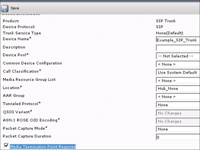
Figure 22-1 Media Termination Point Required Option in the CUCM
If both voice and video calls need to be supported over a SIP trunk, and both Early Offer and Delayed Offer also need to be supported, the better option would be to select the Early Offer Support for Voice and Video Calls Mandatory (Insert MTP if Needed) setting. This option can be enabled from the SIP profile, and it will work with Delayed Offer SIP trunks, Slow Start H.323 trunks, MGCP trunks, and on calls from older Cisco SCCP-based phones. When calls are attempted in these scenarios and this option is enabled, the Cisco Unified Communications Manager will attempt to select an appropriate MTP from the MRGL of the calling device. If no MTP option exists, the Cisco Unified Communications Manager will select an MTP from the MRGL of the trunk.
A third option for Early Offer over a SIP trunk exists within the Cisco Unified Communications Manager; however, this option will not use any MTPs. In the SIP profile, the Early Offer Support for Voice and Video Calls Best Effort (No MTP Inserted) option can be enabled. This setting will allow the SIP trunk to send either Early Offer or Delayed Offer based on the capabilities of the calling endpoint. Figure 22-2 illustrates the Early Offer options that can be configured from a SIP profile on the Cisco Unified Communications Manager.

Figure 22-2 Early Offer Settings in the SIP Profile on the CUCM
For H.323 trunks and gateways, MTPs might be invoked in three circumstances:
H.323 supplementary services
H.323 outbound Fast Start
DTMF conversion
Using H.323 supplementary services is not a common issue that comes up in networks today. If an H.323 endpoint in a call does not support the H.323v2 Open Logical Channel and Close Logical Channel request features of the Empty Capabilities Set (ECS), the supplementary services can still be extended to that endpoint using an MTP. However, since H.323v2 came out in 1998, most all endpoints that use H.323 still in production today support H.323v2.
H.323 has a protocol equivalent to the SIP Early Offer, called Fast Start. However, the Cisco Unified Communications Manager will treat calls using Fast Start differently, depending on where the call originated. Inbound calls to the Cisco Unified Communications Manager that use Fast Start will not need MTP resources. However, outbound calls on an H.323 trunk that have Fast Start enabled will require MTP resources.
We’ve already discussed DTMF signaling and the need for MTPs, but be aware that DTMF conversion may require the use of MTPs depending on the type of H.323 trunk being used and the type of call transmitting across that trunk when DTMF signaling is used during that call.
CUCM Call-Routing Options
Cisco offers a wide variety of voice and video gateways. A gateway provides interfaces that allow the Unified Communications network to communicate with an external network. Traditionally, gateways have been used to connect the IP-based Unified Communications network to legacy telephone interfaces such as the PSTN, a private branch exchange (PBX), or legacy devices such as an analog phone or fax machine. In its simplest form, a voice gateway has an IP interface and a legacy telephony interface, and the gateway translates messages between the two networks so that the two networks can communicate.
Most Cisco gateways offer multiple deployment options and can be deployed using any one of a number of protocols. Depending on the gateway a company may want to deploy, the gateway may be configurable using any of the following communication protocols:
Media Gateway Control Protocol (MGCP)
Skinny Client Control Policy (SCCP)
Session Initiation Protocol (SIP)
H.323
Cisco has been steadily moving away from SCCP over the years. By offering open protocol support that can be used cross-vendor, Cisco can build bridges for customers instead of creating islands. Therefore, this book will not explain how to configure SCCP gateways to IOS XE routers. Chapter 20, “Introduction to Cisco Edge Services,” overviewed the main types of port connections that you can configure on gateways, such as FXS, FXO, T1/E1 CAS, Primary Rate Interface (T1/E1 PRI), Basic Rate Interface (BRI), and so on. Table 22-3 identifies these connection types per the previous protocol list.
Table 22-3 Port Connections per Gateway Type
SCCP |
MGCP |
SIP |
H.323 |
|---|---|---|---|
FXS |
FXS |
FXS |
FXS |
FXS-DID |
FXS-DID |
FXS-DID |
|
E&M |
E&M |
E&M |
|
BRI |
BRI |
BRI |
BRI |
BRI QSIG |
BRI QSIG |
BRI QSIG |
|
T1 CAS |
T1 CAS |
||
T1 FGD |
T1 FGD |
||
E1 CAS |
E1 CAS |
||
T1/E1 PRI |
T1/E1 PRI |
||
T1/E1 QSIG |
T1/E1 QSIG |
||
T1/E1 NFAS |
T1/E1 NFAS |
||
T1/E1 PRI (MegacomISDN) |
T1/E1 PRI (MegacomISDN) |
||
Centralized Automatic Message Accounting (CAMA) |
Centralized Automatic Message Accounting (CAMA) |
Before configuring the gateway in Cisco Unified Communications Manager, you must perform several tasks on the gateway hardware first. You need to install and configure the gateway, install any vendor interface cards (VICs) on the gateway, and use the CLI to configure IOS on the gateway. For details on how to perform the vendor-specific tasks, refer to the hardware and software documentation that comes with your gateway.
The Call Classification setting determines whether a gateway is external (OffNet) or internal (OnNet). It is configured using a clusterwide service parameter, as explained previously, or by configuring any of the following port interfaces:
MGCP BRI port interfaces
MGCP FXO port interfaces
H.323 gateways
SIP trunks
By default, each gateway port interface is configured to use the setting from the clusterwide service parameter. However, if Call Classification on a port is configured differently from the clusterwide service parameter, the setting on that port overrides the service parameter setting. You can use the following steps to configure the Call Classification setting for your network gateways under Service Parameters:
Step 1. From Cisco Unified Communications Manager Administration, navigate to System > Service Parameters.
Step 2. From the Server drop-down list, choose the server on which the Cisco CallManager service is running.
Step 3. From the Service drop-down list, choose Cisco CallManager.
Step 4. Under Clusterwide Parameters (Device - General), configure one of the following values for the Call Classification service parameter:
OnNet: Calls from this gateway are classified as originating from inside the company network.
OffNet: Calls from this gateway are classified as originating from outside the company network.
Step 5. Click Save.
By default, the Cisco Unified Communications Manager allows transfers from one external gateway to another external gateway. To block calls that are transferred from one external (OffNet) gateway to another external (OffNet) gateway, use the following steps:
Step 1. From the previous steps you should still be under System > Service Parameters > Cisco CallManager service.
Step 2. Configure a setting for the Block OffNet to Offnet Transfer service parameter:
True: Select this option to cancel transfers between two external (OffNet) gateways.
False: Select this option to allow transfers between two external (OffNet) gateways. This is the default option.
Step 3. Click Save.
You can also classify calls through a gateway as OnNet or OffNet by associating the gateway to a route pattern and configuring Call Classification in the Route Pattern Configuration window. After configuring these settings, you can also configure the gateway settings on the Cisco Unified Communications Manager. The following sections will outline how to configure MGCP, H.323, and SIP gateways.
MGCP Gateway
The following procedure enables you to add and configure an MGCP (IOS) gateway on the Unified Communications Manager:
Step 1. From Cisco Unified Communications Manager Administration, navigate to Device > Gateway.
Step 2. Click Add New.
Step 3. From the Gateway Type drop-down list, select the gateway and click Next.
Step 4. From the Protocol drop-down list, choose MGCP and click Next.
Step 5. In the Configured Slots, VICs and Endpoints area, perform the following steps:
From each Module drop-down list, select the slot that corresponds to the Network Interface Module hardware that is installed on the gateway.
From each Subunit drop-down list, select the VIC that is installed on the gateway.
Click Save.
The Port icons appear. Each Port icon corresponds to an available port interface on the gateway. You can configure any port interface by clicking the corresponding Port icon.
Step 6. Complete the remaining fields in the Gateway Configuration window. For more information on the fields, see the system’s online help.
Step 7. Click Save.
You can configure the BRI port interface for an MGCP (IOS) gateway as follows:
Step 1. In the Cisco Unified Communications Manager Administration, navigate to Device > Gateway.
Step 2. Click Find and select the gateway on which you want to configure PRI ports.
Step 3. In the Configured Slots, VICs, and Endpoints area, locate the Module and Subunit that contain the BRI port that you want to configure and click the Port icon that corresponds to the BRI port that you want to configure.
The Gateway Configuration window displays the BRI port interface.
Step 4. From the Device Pool drop-down list, select a device pool.
Step 5. Complete the remaining fields in the Gateway Configuration window. Refer to the online help for field descriptions.
Step 6. Click Save.
Step 7. (Optional) If you want to configure more port interfaces for the gateway, from the Related Links drop-down list, choose Back to MGCP Configuration and click Go.
Step 8. The Gateway Configuration window displays the available port interfaces for the gateway.
Most gateways need to be reset for configuration changes to take effect. Cisco recommends that all necessary gateway configurations are complete before performing a reset. Resetting an H.323 gateway only reinitializes the configuration that Cisco Unified Communications Manager loaded and does not physically restart or reset the gateway.
Step 1. From Cisco Unified Communications Manager Administration, navigate to Device > Gateway.
Step 2. Click Find and select the gateway.
Step 3. Click the check box beside the gateway that you want to reset and click Reset Selected.
Step 4. The Device Reset dialog box appears. Click Reset.
H.323 Gateway
You can configure an H.323 gateway in the Cisco Unified Communications Manager for a non-gatekeeper H.323 deployment. If your deployment includes H.323 gatekeepers, you can also add an H.323 gateway by setting up a gatekeeper-controlled H.225 trunk. This scenario is not documented in this book because gatekeeper usage has been in steady decline over the years. If you want to configure gatekeepers and H.225 gatekeeper-controlled trunks, refer to the Cisco Unified Communications Manager Administration Guide, Release 10.0(1) (yes, this is an older and outdated guide, just like the H.323 gatekeepers). Note that when a gateway is registered with Cisco Unified Communications Manager, the registration status may be displayed in Cisco Unified Communications Manager Administration as unknown.
Step 1. From Cisco Unified Communications Manager Administration, navigate to Device > Gateway.
Step 2. Click Add New.
Step 3. From the Gateway Type drop-down list, choose H.323 Gateway.
Step 4. In the Device Name field, enter the IP address or hostname of the gateway.
Step 5. If you want to use H.235 to configure a secure channel, check the H.235 Data Passthrough check box.
Step 6. Configure the fields in the Gateway Configuration window. For more information on the fields and their configuration options, see the system’s online help.
Step 7. Click Save.
Step 8. Click Reset to reset the gateway and apply the changes.
Most gateways need to be reset for configuration changes to take effect. We recommend that you complete all necessary gateway configuration before performing a reset.
SIP Trunk
You can configure a SIP profile for your SIP trunk connection:
Step 1. From Cisco Unified Communications Manager Administration, navigate to Device > Device Settings > SIP Profile.
Step 2. Perform either of the following steps:
Click Add New to create a new profile.
Click Find to select an existing SIP profile.
Step 3. Complete the fields in the SIP Profile Configuration window. For more information on the fields and their configuration options, see the system’s online help.
Step 4. Click Save.
You also can configure a SIP trunk security profile with security settings for a trunk that connects to a SIP gateway:
Step 1. In Cisco Unified Communications Manager Administration, navigate to System > Security > SIP Trunk Security Profile.
Step 2. Perform either of the following steps:
Click Find to select an existing profile.
Click Add New to create a new profile.
Step 3. Complete the fields in the SIP Trunk Security Profile Configuration window. For more information on the fields and their configuration options, see the system’s online help.
Step 4. Click Save.
Finally, you can configure a SIP trunk to connect Cisco Unified Communications Manager to a Cisco or third-party gateway that uses SIP. Under this configuration, do not enter the gateway as a device in the Gateway Configuration window:
Step 1. From Cisco Unified Communications Manager Administration, navigate to Device > Trunk.
Step 2. Click Add New to set up a new SIP trunk.
Step 3. From the Trunk Type drop-down list, choose SIP Trunk.
Step 4. From the Protocol drop-down list, choose None.
Step 5. In the Destination Address field of the SIP Information pane, enter an IP address, fully qualified domain name, or DNS SRV record for the SIP gateway.
Step 6. From the SIP Trunk Security Profile drop-down list, choose the SIP trunk security profile that you configured for this gateway.
Step 7. From the SIP Profile drop-down list box, choose the SIP profile that you configured for this gateway.
Step 8. Complete the fields in the SIP Trunk Configuration window. Refer to the online help for field descriptions.
Step 9. Click Save.
Cisco IOS XE Gateway Settings for ISDN Routing
Of the three different gateway types mentioned in the previous section, SIP is the easiest to deploy and support. Therefore, Cisco recommends using the SIP gateway between the Cisco Unified Communications Manager and the IOS XE gateway. On the IOS XE router, you should configure the following settings before configuring an ISDN voice interface:
Obtain PRI or BRI service and T1 or E1 service from your service provider, as required. Ensure that the BRI lines are provisioned at the switch to support voice calls.
Establish a working IP, Frame Relay, or ATM network. Ensure that at least one network module or WAN interface card is installed in the router to provide connection to the LAN or WAN.
Complete your company’s dial plan.
Establish a working telephony network based on your company’s dial plan and configure the network for real-time voice traffic.
For the Cisco 2600 series and Cisco 3600 series, install digital T1 or E1 packet-voice trunk network modules, BRI voice interface cards, and other voice interface cards as required on your network.
For the Cisco 7200 series, install a single-port 30-channel T1/E1 high-density voice port adapter.
For the Cisco MC3810, install the required digital voice modules (DVMs), BRI voice modules (BVMs), and multiflex trunk modules.
Configure the following for all platforms (as required):
Voice card and controller settings
Serial and LAN interfaces
Voice ports
Voice dial peers
Codec Preference List
Much of this book has been dedicated to explaining codecs. There is at least one codec for each function in voice and video communication. The Cisco Unified Communications Manager uses regions to control codec selection when routing calls. Codecs, such as G.729, can be used to compress digital voice samples to reduce bandwidth usage per call when routing across the WAN or out to the PSTN.
Configuring codecs on an IOS XE gateway allows the router to act as a demarcation point on a VoIP network and allows a dial peer to be established only if the desired codec criteria are satisfied. Preferences can be used to determine which codecs will be selected over others. A codec voice class is a construct within which a codec preference order can be defined. A codec voice class can then be applied to a dial peer, which then follows the preference order defined in the codec voice class. You can use the following commands to configure a codec voice class with a codec preference list:
Router> enable
Router# configure terminal
Router(config)# voice class codec <tag>
Do the following for each audio codec you want to configure in the voice class:
Router(config-class)# codec preference value codec-type[ bytes
payload-size fixed-bytes ]

Router(config-class)# codec preference value isac [ mode {adaptive
| independent} [bit-rate value framesize { 30 | 60 } [fixed] ]

Router(config-class)# codec preference value ilbc [ mode
frame-size [bytes payload-size] ]

Router(config-class)# codec preference value mp4-latm [profile tag]

Router(config-class)# exit
The following explanations should help administrators understand what function each command performs. The enable command enables privileged EXEC mode. You then enter your password if prompted. The configure terminal command enters global configuration mode. The voice class codec <tag> command enters voice-class configuration mode for the specified codec voice class. The <tag> at the end of the command is the value used to identify this voice class. After the administrator has entered the voice-class configuration mode, the following commands must be entered for each audio codec that needs to be configured in the voice class. Configuring a codec within the voice class specifies a preference for the codec and becomes part of a preference list.
codec preference <value> <codec-type> [ bytes <payload-size> fixed-bytes ]
codec preference <value> isac [mode {adaptive | independent} [bit-rate <value> framesize { 30 | 60 } [fixed] ]
codec preference <value> ilbc [ mode <frame-size> [bytes <payload-size>] ]
codec preference <value> mp4-latm [profile <tag>]
The first command in the preceding list should be used for every codec except isac, ilbc, or mp4-ltam. The <value> item in each of the commands is just a numeric value the administrator assigns to each codec preference for reference when assigning them to a dial peer. After all codecs have been configured, you can use the exit command to back out of the voice-class configuration mode.
Voice class preferences can be used for audio codecs, but video codecs just use the voice class. From the global configuration mode, you enter the same voice class codec <tag> command as before. The next command should be video codec <codec>, such as video codec h264. The last step is to apply the voice class to the applicable dial peers. This step can be performed at the time the dial peer is created, or it can be added to a dial peer after it already exists. A voice class can contain both audio codec preferences and video codecs. The next section will cover more information on the commands to use at the dial peer.
Dial Peers
Cisco IOS XE routers use the concept of dial peers to route calls. Every call that traverses through the router has to match an inbound dial peer and an outbound dial peer. Each router will have physical ingress and egress ports that data traffic will flow though. Multiple ports could exist on each router, and different mediums could be used for traffic traversing those ports. Specifically, IP traffic could cross a LAN or WAN packet-switched port, and PSTN traffic could cross a circuit-switched port all on the same router. The call could have originated within the corporate network, at a remote location, or from the PSTN. Dial peers are the routing patterns that determine how and where calls should be routed based on the ingress and egress ports on the router. Figure 22-3 illustrates the dial peers needed for a LAN and PSTN-connected router.

Figure 22-3 Dial-Peer Concept on a Cisco IOS XE Router
Figure 22-3 illustrates the need to have dial peers for inbound and outbound calls. Also, note that Gigabit Ethernet ports 0/0 and 0/1 use VoIP dial peers, whereas the Serial 0:23 T1 port uses POTS dial peers. Best practice is to explicitly define the inbound and outbound dial peers for inbound and outbound calls. We can generalize them in three broader sets: LAN VoIP dial peers, WAN VoIP dial peers, and PSTN POTS dial peers, as explained in the list that follows:
LAN dial peers reside toward the enterprise network. These will act as
Inbound dial peers for calls from Cisco Unified Communications Manager toward the PSTN or WAN.
Outbound dial peers for calls to Cisco Unified Communications Manager from PSTN or WAN.
WAN dial peers allow connections between a headquarters office and branch offices or a service provider’s network when used with CUBE. These will act as
Inbound dial peers for calls from a service provider toward Cisco Unified Communications Manager (to accept call legs from a service provider to CUBE) or for calls from a branch office across the WAN toward the Cisco Unified Communications Manager.
Outbound dial peers for calls to a service provider from Cisco Unified Communications Manager (to originate call legs from CUBE to a service provider) or for calls from Cisco Unified Communications Manager to a branch office across the WAN.
POTS dial peers map a dialed string to a specific voice port on the local router, normally the voice port connecting the router to the local PSTN, private branch exchange (PBX), or telephone.
Inbound POTS dial peers are associated with incoming POTS call legs on the originating router toward Cisco Unified Communications Manager.
Outbound POTS dial peers are associated with outgoing POTS call legs originating from the Cisco Unified Communications Manager toward the POTS ports on the router.
This book will focus on LAN dial peers and POTS dial peers from this point forward. The dial-peer matching algorithm offers a number of ways in which a particular dial peer can be matched. The four configurable Cisco IOS dial-peer attributes and corresponding call setup elements are as follows:
Incoming called-number <DNIS_string>: This dial-peer command defines the called number destination or Dialed Number Identification Service (DNIS) string. When properly configured, this dial-peer command uses the called number to match the incoming call leg to an inbound dial peer.
Answer-address <ANI_string>: This dial-peer command defines the originating calling number or automatic number identification (ANI) string. When properly configured, this dial-peer command uses the calling number to match the incoming call leg to an inbound dial peer.
Destination-pattern <string>: When inbound call legs are matched, this command uses the calling number (originating or ANI string) to match the incoming call leg to an inbound dial peer. Note that for outbound dial peers, this command is matched against the called number or DNIS strings.
Port <port> (for TDM gateways): This dial-peer command defines the POTS voice port through which calls to this dial peer are placed.
Called number (DNIS) is the call destination dial string and is derived from the ISDN setup message or channel associated signaling (CAS) DNIS. Calling number (ANI) is a number string that represents the original dialed number, and it is derived from the ISDN setup message or CAS ANI. The ANI is also referred to as calling line identification (CLID). Voice port represents the POTS physical voice port.
When the Cisco IOS XE router receives a call setup request, a dial-peer match is made for the incoming call in order to facilitate routing the call to different session applications. This is not a digit-by-digit match; rather, the full digit string received in the setup request is used to match against configured dial peers. The router matches the information elements in the setup message with the dial-peer attributes to select an inbound dial peer. The router or gateway matches these items in a specific order:
Called number (DNIS) with the incoming called-number command.
Calling number (ANI) with the answer-address command.
Calling number (ANI) with the destination-pattern command.
Voice port (associated with the incoming call setup request) with configured dial-peer port (applicable for inbound POTS call legs).
If no match is found in the first four steps, the default dial peer 0 (pid:0) command is used.
The longest prefix matching criteria apply while each of the preceding steps is performed. At each step, if multiple matches are found, the one with the longest explicit match is chosen. The Cisco IOS XE router will match only one of these conditions. Therefore, it is not necessary for all the attributes to be configured in the dial peer or that every attribute match the call setup information. Only one condition must be met for the router to select a dial peer. The router will stop the search as soon as one dial peer is matched.
In the first step of the dial-peer selection process, the router attempts to match the called number of the call setup request with the configured incoming called-number of each dial peer. Because call setups always include DNIS information, it is recommended to use the incoming called-number command for inbound dial-peer matching. Assume there were two dial peers configured as follows in Example 22-1.
Example 22-1 POTS Dial Peers Using Called-Number Command
Router(config)# dial-peer voice 1 pots
Router(config-dial-peer)# incoming called-number 5......
Router(config-dial-peer)# direct-inward-dial
! and
Router(config)# dial-peer voice 2 pots
Router(config-dial-peer)# incoming called-number 555….
Router(config-dial-peer)# direct-inward-dial
Which of the dial peers in Example 22-1 will be chosen if a user dials the alias 5551212? Both dial peers use the called number DNIS method, so neither dial peer is chosen based on the dial-peer search order. However, dial-peer voice 2 pots does have a closer “longest prefix match,” so the router will choose dial-peer 2 over dial-peer 1.
The incoming called-number attribute has matching priority over the answer-address and destination-pattern commands. However, if no match is found in step 1, the router attempts to match the calling number of the call setup request with the answer-address of each dial peer. This attribute can be useful in situations where you want to match calls based on the calling number or source of the call. Consider the following dial peers in Example 22-2.
Example 22-2 POTS Dial Peers Using Three Different Commands
Router(config)# dial-peer voice 1 pots
Router(config-dial-peer)# destination-pattern 5552001
Router(config-dial-peer)# port 1/0/0
Router(config)# dial-peer voice 2 pots
Router(config-dial-peer)# answer-address 555100.
Router(config-dial-peer)# port 2/1/0
Router(config)# dial-peer voice 3 pots
Router(config-dial-peer)# incoming called-number 555100.
Router(config-dial-peer)# port 2/1/0
Router(config)# dial-peer voice 4 pots
Router(config-dial-peer)# destination-pattern 555100.
Router(config-dial-peer)# forward-digits all
Router(config-dial-peer)# port 2/1/0
Using the dial peers in Example 22-2, imagine a scenario where a caller with the calling number of 5551001 dials the called number of 5552001. As mentioned before, the incoming called-number command has the first priority and does exist in dial peer 3. However, the called number of 5552001 does not match the incoming called-number pattern of 555100. The answer-address command has second priority. It exists in dial-peer 2 and matches the calling number of 5551001 with the pattern 555100.
If no match is found in step 2, the router attempts to match the calling number of the call setup request to the destination-pattern of each dial peer. In Example 22-2 there are two destination-patterns. Dial-peer 1 matches an exact alias of 5552001, and dial peer 4 matches an alias pattern of 555100. The destination-pattern rule matches on the calling number, which is 5551001, so dial peer 4 will be used in the event the incoming called-number and answer-address cannot be used.
If no match is found in step 3, the router attempts to match the configured dial-peer port to the voice port associated with the incoming call. If multiple dial peers have the same port configured, the dial peer first added in the configuration is matched. Examining the incoming POTS dial peers in Example 22-2 again, you can see three dial peers that are using port 2/1/0. If this port were the incoming port over the POTS network, the first dial peer in the list would be the first added dial peer. Therefore, dial-peer 2 would be used to route the call.
If no incoming dial peer is matched by the router, the inbound call leg is automatically routed to a default dial peer. This default dial peer is referred to as dial-peer 0 or pid:0. Dial-peer 0 has a default configuration that cannot be changed. The default dial-peer 0 fails to negotiate nondefault capabilities, services, and applications such as nondefault voice-network capabilities like dtmf-relay, no vad, and so on. Other capabilities, services, and applications include direct inward dialing (DID) and TCL applications. dial-peer 0 for inbound VoIP peers has this configuration:
any codec
vad enabled
no rsvp support
fax-rate voice
dial-peer 0 (pid:0) for inbound POTS peers has the configuration no ivr application.
To match outbound dial peers, the router uses the dial-peer destination-pattern <called_number> command. On POTS dial peers, the port command is then used to forward the call. On VoIP dial peers, the session target command is then used to forward the call. Also, when outbound peers are matched, there are two cases to consider: DID case and non-DID.
An incoming dial peer configured with DID looks like the following:
Router(config)# dial-peer voice 1 pots

Router(config-dial-peer)# incoming called-number <called_number>

Router(config-dial-peer)# voice-port 0:D

Router(config-dial-peer)# direct-inward-dial
On DID calls, also referred to as one-stage dialing, the setup message contains all the digits necessary to route the call, and the router or gateway should not do subsequent digit collection. When the router or gateway searches for an outbound dial peer, the device uses the entire incoming dial string. This matching is variable-length by default. This match is not done digit-by-digit because, by DID definition, all digits have been received.
The non-DID case is referred to as two-stage dialing. If DID is not configured on the matched incoming dial peer, the router or gateway enters the digit collection mode, and digits are collected in-band. Outbound dial-peer matching is done on a digit-by-digit basis. The router checks for dial-peer matches after the device has received each digit and then routes the call when a full match is made. Imagine a router has the following dial peers configured:
Router(config)# dial-peer voice 3 voip

Router(config-dial-peer)# destination-pattern 816

Router(config-dial-peer)# session target ipv4:172.22.10.1

Router(config)# dial-peer voice 4 voip

Router(config-dial-peer)#  destination-pattern 81690

Router(config-dial-peer)#  session target ipv4:172.22.10.1
If the dial-string is 81690, then immediately after the router receives the digit 6, the router matches dial-peer 3 and routes the call (forwarding only the digits 816). Now, assume dial-peer 3 is configured for wildcard matching. In this case, the longest-prefix rule applies, and dial-peer 4 is matched for the outbound call leg, as demonstrated here:
Router(config)# dial-peer voice 3 voip

Router(config-dial-peer)# destination-pattern 816..

Router(config-dial-peer)# session target ipv4:172.22.10.1

Router(config)# dial-peer voice 4 voip

Router(config-dial-peer)#  destination-pattern 81690

Router(config-dial-peer)#  session target ipv4:172.22.10.1
The previous section discussed how to configure a codec preference list. These lists must be applied to dial peers. The first step on the router is to enter the dial-peer configuration mode for the specified VoIP dial peer. You can use the command dial-peer voice <number> voip, where <number> is the assigned value for the dial peer. The next command should be voice-class codec <tag> offer-all, where <tag> is the value identifying the voice class created. This command applies the previously configured voice class and associated codecs to a dial peer. The offer-all keyword allows the device to offer all codecs configured in a codec voice class. No further commands are needed to apply the voice class to the dial peer. For more information on dial peers, refer to the following link: http://www.cisco.com/en/US/tech/tk652/tk90/technologies_tech_note09186a008010fed1.shtml.
Voice Translation Rules and Profiles
Chapter 19, “Configuring Globalized Call Routing in Cisco Unified Communications Manager,” discussed how calling and called aliases can be transformed using translation patterns and transformation patterns on the Cisco Unified Communications Manager. In a similar manner, the Cisco IOS XE router can transform aliases using voice translation rules and profiles. A profile can translate called, calling, or redirecting numbers. Voice translation rules are applied to voice translation profiles. These profiles are then applied to dial peers or voice ports. Profiles can be applied to VoIP or POTS dial peers or voice ports, and they can be applied to inbound or outbound calls.
Some simple matches and replaces can be implemented using voice translation rules and profiles. Once an engineer becomes more familiar with these rules, wildcards, number slices, and other tricks can be used to create more complex but granular rules for controlled call routing across the IOS XE router. First, let’s look at how a simple match and replace can be configured using a voice translation rule.
An administrator can create a rule from the configuration mode on the router by entering the following command:
Router(config)# voice translation-rule 1
On the next line, the parameters of the rule can be created using the following command:
Router(cfg-translation-rule)# rule 1 /1001/ /2001/
This rule will match the alias 1001 and replace it with the alias 2001. There are some test commands that can be used to verify the voice translation rules operate the way they are designed. From the Privileged Exec Mode on the router, enter the command test voice translation-rule 1 1001. This command identifies the rule to be tested followed by the alias to use for the testing. Example 22-3 illustrates some test results that can be expected using this test command.
Example 22-3 Test Voice Translation Rule Examples
Router# test voice translation-rule 1 1001
Matched with rule 1
Original number: 1001             Translated Number 2001
Router# test voice translation-rule 1 10011
Matched with rule 1
Original number: 10011            Translated Number 20011
Router# test voice translation-rule 1 5551001
Matched with rule 1
Original number: 5551001          Translated Number 5552001
Router# test voice translation-rule 1 10011001
Matched with rule 1
Original number: 10011001         Translated Number 20011001
In Example 22-3 the rule matches the first occurrence of the number that contains the pattern 1001. A wildcard symbol, called the start-of-number indicator, can be used to require the number to be the first digits matched; this symbol is a caret (^). There is also a wildcard symbol called an end-of-number indicator to signify the last digit to be represented; this symbol is a dollar sign ($). Using both of these symbols together creates an exact match pattern. Modifying the pattern in translation rule 1, the pattern /^1001/ /2001/ will match dial string 1001 and replace it with 2001, and it will match dial string 10011 and replace it with 20011. It will not match dial string 5551001 because this dialed number does not begin with 1001. Modifying the pattern in translation rule 1, the pattern /1001$/ /2001/ will match dial string 1001 and replace it with 2001, and it will match dial string 5551001 and replace it with 5552001. It will not match dial string 10011 because this dialed number does not end with 1001. If you modify the pattern in translation rule 1 to /^1001$/ /2001/, the only dial string that will match, and therefore be translated, is 1001. Table 22-4 identifies some additional wildcard symbols that you can use for pattern matching on Cisco IOS XE routers for voice translation rules.
Table 22-4 Wildcards for Translation Rule Pattern Matching
Wildcard |
Definition |
|---|---|
. |
Any single digit. |
0 to 9, *, # |
Any specific character. |
[0–9] |
Any range or sequence of characters. |
* |
Modifier match; none or more occurrences. |
+ |
Modifier match; one or more occurrences. |
? |
Modifier match; none or one occurrence. |
.* |
Any digit followed by none or more occurrences. This is effectively anything or nothing. |
.+ |
Any digit followed by one or more occurrences. This is effectively anything but cannot be nothing. |
^$ |
No digits, null. |
Working with these wildcard characters takes some practice. Within a short amount of time, you will find yourself much more proficient using these wildcards than you thought possible. The following examples will help illustrate how these wildcards can be used in translation rules. If a translation rule had the pattern /555..../ /2001/, any four-digit number that follows 555 would be matched and changed to 2001. Therefore, 5551001 would be changed to 2001. If a translation rule had the pattern /.*/ /5552001/, then any number dialed composed of any number of digits would be matched and changed to 5552001. Therefore, if the number 9 was dialed, it would be changed to 5552001. The same is true if the number 44083451001 was dialed. It would be changed to 5552001. If a translation rule had the pattern /^0+/ /909/, only numbers dialed that began with a combination of 0 would be matched. This would include 0 or 00 or any number of zeros. The replacement for the 0 only would be 909. If the number 05551001 was dialed, then this translation rule would change the number to 9095551001.
In addition to the wildcards listed in Table 22-4, some other characters can be used to slice numbers. You can use a number slice when you need to copy parts of a matched number and use those parts in the replacement number. The matched number can be sliced into sets that are kept or ignored. Table 22-5 identifies the characters used for number slices.
Table 22-5 Characters Used for Number Slice
Character |
Description |
|---|---|
In the match pattern, indicates where to slice up the number. |
|
In the replacement pattern, indicates where to paste the copied sets of numbers that are kept. |
|
( ) |
Indicates which sets in the matched number to keep. |
(a) |
Copies expression “a”. |
b |
Ignores expression “b”. |
1 |
Pastes the first set into the replacement number. |
This is where reading a voice translation can become quite confusing. Just remember that the forward slash (/) indicates the beginning and ending of the match string and the replacement string. The backslash () used in the match string will divide the matched number into sets. If parentheses are used around digits in the match number, such as “(919)”, these digits are copied into a set and will be replaced where indicated in the replacement string. If multiple sets of parentheses are used in a pattern match, they are numbered from left to right. If a set of digits is followed by a forward slash without parentheses, such as “555”, then these digits are ignored in the replacement string. Imagine a voice translation rule that looked like the following:
Router(config)# Voice Translation-rule 2

Router(cfg-translation-rule)# Rule 1 /(919)555(1001)/  /14442/
In the match pattern, the “(919)” is set 1 and the “(1001)” is set 2. The “555” does not have parentheses around it, so these digits will be ignored. In the replacement string, the “1” and “2” indicate where the copied sets from the pattern match are to be pasted. Therefore, if a user were to dial 9195551001, this rule would translate the number to 9194441001.
Another function in voice translation rules is to restrict matches to particular number types or number plans. Because this chapter deals with sending IP-based calls out the PSTN, and vice versa, the number type and number plan function are particularly important. The PSTN sends a type of number, or TON, record with each telephony transaction. There are two components of a TON: the number type of a called number and the numbering plan. Basically, four different “types” of numbers can be used; they are Cisco CallManager, National, International, or Unknown, which is the default. Different “plans” can be used as well, such as Cisco CallManager, ISDN, National Standard, Private, or Unknown. Each of these types and plans can be used to determine when and how a translation rule should be applied. This capability is useful when telephone companies remove access codes on national and international numbers. Administrators can add the correct prefix with the number type as a basis. Example 22-4 illustrates how a voice translation rule can be configured using type and plan and what an outcome would look like.
Example 22-4 Voice Translation Rule Using Type and Plan
Router(config)#
voice translation-rule 3
Router(cfg-translation-rule)# rule 1 /(^555)(….$)/ /91912/ type unknown national
plan unknown isdn
Router# test voice translation-rule 3 5551001 type unknown plan unknown
Matched with rule 1
Outgoing number: 5551001                   Translated number: 9195551001
Original number type: unknown              Translated number type: national
Original number plan: unknown              Translated number plan: isdn
Voice translation rules can also use the keyword reject to reject calls that match a certain pattern. If a rule looked like rule 1 reject /^555/, any dialed alias that started with 555 would be rejected. If a user dialed 9195551001, this alias would not match the rule and could be routed. However, if the user dialed 5551001, this alias would match the pattern of the reject rule and the call would fail. This reject rule is great to use with tolled numbers that employees should not be calling, such as 1-900-trixxxy or other such numbers.
Voice translation rules are applied to voice translation profiles. These profiles are then applied to dial peers or voice ports. Profiles can be applied to VoIP or POTS dial peers or voice ports, and can be applied to inbound or outbound calls. A profile can translate called, calling, or redirecting numbers. Example 22-5 illustrates how to create a voice translation rule and profile and to apply the profile to a dial peer.
Example 22-5 Voice Translation Rule, Profile, and Apply to Dial Peer
Router(config)# voice translation-rule 1
Router(cfg-translation-rule)# rule 1 /^1001$/ /2001/
Router(config)# Voice Translation-rule 2
Router(cfg-translation-rule)# Rule 1 /(919)555(1001)/  /14442/
Router(config)# voice translation-rule 3
Router(cfg-translation-rule)# rule 1 /(^555)(….$)/ /91912/ type unknown national
plan unknown isdn
Router(config)# voice translation-profile profile1
Router(cfg-translation-profile)# translate calling 1
Router(cfg-translation-profile)# translate calling 2
Router(cfg-translation-profile)# translate calling 3
Router(config)# dial-peer voice 100 pots
Router(config-dial-peer)# translation-profile outgoing profile1
Configure and Troubleshoot ISDN BRI
ISDN BRI or PRI settings should be configured before the dial peers on Cisco IOS XE routers so that the ports can be applied to the appropriate POTS dial peers. Although this chapter does not provide all the steps in the order they should be configured, it does provide all the steps necessary to configure an IOS XE router for TDM support and access. This section contains the steps for configuring a router with ISDN BRI voice interface support.
Step 1: Configuring BRI NT and TE Interfaces
To configure BRI NT and TE interfaces, you can perform the following steps. To do so, set up each channel for either the user side or network side. On the Cisco IOS XE router, enter the following commands:
Router> enable

Router# configure terminal

Router(config)# isdn switch-type <switch-type>

Router(config)# interface bri <slot/port>

Router(config-if)# no ip address

Router(config-if)# isdn overlap-receiving

Router(config-if)# isdn twait-disable

Router(config-if)# isdn spid1 <spid-number [ldn]>

Router(config-if)# isdn spid2 <spid-number [ldn]>

Router(config-if)# isdn incoming-voice {voice | modem}

Router(config-if)# shutdown

Router(config-if)# isdn layer1-emulate {user | network}

Router(config-if)# no shutdown

Router(config-if)# network-clock-priority {low | high}

(Cisco MC3810 Only) Router(config-if)# line-power

Router(config-if)# isdn protocol-emulate {user | network}

Router(config-if)# isdn sending-complete

Router(config-if)# isdn static-tei <tei-number>

Router(config-if)# isdn point-to-point-setup

Router(config-if)# end

Router# clear interface bri <slot/port>
Many commands are used to set up BRI NT and TE interfaces on a Cisco IOS XE router. The following explanations should help administrators understand what function each command performs. The enable command enters privileged EXEC mode on the router. You can enter a password if prompted. The configure terminal command enters the configuration mode on the router. The isdn switch-type <switch-type> command configures the telephone-company ISDN switch type. The only switch types currently supported for an NT interface are basic-net3 and basic-qsig. The following is an example of how this command might look when configured in the router:
Router(config)# isdn switch-type basic-qsig
The interface bri <slot/port> command enters the interface configuration mode for the specified port, connector, or interface card number, which is the location of the voice network module and voice interface card. The command may be slightly different on Cisco MC3810 routers than other supported models. The MC3810 command is interface bri <number>, whereas the command on other models uses slot/port, as shown above. The no ip address command specifies that there is no IP address for this interface.
Four optional commands can be configured when setting up the BRI interfaces. The optional isdn overlap-receiving command activates overlap signaling to send to the destination PBX. In this mode, the interface waits for possible additional call-control information. Another optional command is isdn twait-disable; this command delays a national ISDN BRI switch for a random length of time before activating the Layer 2 interface at switch startup. You can use this command when the ISDN switch type is basic-ni1. Twait time is enabled by default. The third optional command is for TE setup only. The isdn spid1 command is a service profile identifier (SPID) and optional local directory number for the B1 channel. Currently, only DMS-100 and NI-1 switch types require SPIDs. Although some switch types might support a SPID, Cisco recommends that you set up ISDN service without SPIDs. Similarly, the isdn spid2 command specifies the SPID and optional local directory number for the B2 channel.
The isdn incoming-voice {voice | modem} command configures the port for incoming ISDN voice calls to be handled by either a modem or a voice DSP, as directed by the call-switching module. Once this command has been issued, the port needs to be shut down. The shutdown command turns off the port so that the port emulation can be set.
Port emulation can be set one of two ways: either by the user side or the network side. The user side configures Layer 1 port mode emulation and clock status for the user—that is, the TE (clock slave). The command to use for the user side is isdn layer1-emulate user. The network side configures Layer 1 port mode emulation and clock status for the network—that is, the NT (clock master). The command to use for the network side is isdn layer1-emulate network. After port emulation has been configured, the port can be turned on again using the no shutdown command.
The network-clock-priority command is another optional command for TE only. This command sets the priority for recovering a clock signal from the network NT device for this BRI voice port. Following the preceding command is either low or high. High provides a first priority, which is the default for BRI voice interface cards. Low provides a low priority, which is the default for BRI voice modules. You should not use this command if the port is configured as NT in the previous port emulator command.
Only Cisco MC3810 routers need to use this next command. The line-power command turns on the power supplied from an NT-configured port to a TE device.
Another port emulation command needs to be issued for Layer 2 and Layer 3. The user-side command (isdn protocol-emulate user) configures Layer 2 and Layer 3 port mode emulation and clock status for the user—that is, the TE (clock master). The network-side command (isdn protocol-emulate network) configures Layer 2 and Layer 3 port mode emulation and clock status for the network—that is, the NT (clock slave).
The optional isdn sending-complete command configures the voice port to include the “Sending Complete” information element in the outgoing call-setup message. This command is used in some geographic locations, such as Hong Kong and Taiwan, where the “Sending Complete” information element is required in the outgoing call setup message. Another optional command is isdn static-tei <tei-number>. This command configures a static ISDN Layer 2 terminal endpoint identifier (TEI). A third optional command is isdn point-to-point-setup. This command configures the ISDN port to send SETUP messages on the static TEI (point-to-point link). A static TEI must be configured in order for this command to be effective.
After all of these commands have been configured, you can use the end command to exit the configuration mode completely. The administrator can now optionally decide to reset the specified port, connector, or interface card number (location of voice module) or slot/port (location of voice network module and voice interface card). The interface needs to be reset if the static TEI number was configured. Cisco MC3810 routers will use the command clear interface bri <number>. All other Cisco router models will use the command clear interface bri slot/port.
Step 2: Verifying the BRI Interfaces
The BRI ports should all be set up at this point. The next step is to verify the BRI interfaces using the following commands:
Router# show controllers bri <number> or show controllers bri
<slot/port>

Router# show interfaces bri

Router# show isdn {active [serial-number] | history [serial-number]}

Router# show isdn {memory | status | timers}

Router# show isdn status

Router# show running-config

Router# show voice port {<slot/port> | summary}
The following explanations will identify what each show command reveals about the BRI interfaces. The show controllers bri <number> or show controllers bri <slot/port> command will display information about the specified BRI port, connector, or interface card number (location of voice module) or slot/port (location of voice network module and voice interface card). The show interfaces bri command will display information about the physical attributes of the BRI B- and D-channels. In the output, look for the term spoofing, which indicates that the interface presents itself to the Cisco IOS software as operational. Use the show isdn {active [serial-number] | history [serial-number]} command to display current (active keyword) or both historic and current (history keyword) call information for all ISDN interfaces or, optionally, a specific ISDN PRI interface (created and configured as a serial interface). Information displayed includes called number, remote node name, seconds of connect time, seconds of connect time remaining, seconds idle, and advice of charge (AOC) charging time units used during the call. The show isdn {memory | status | timers} command is used to display information about memory, status, and Layer 2 and Layer 3 timers. The show isdn status command is used to display the status of all ISDN interfaces, including active layers, timer information, and switch-type settings. The show running-config command is used to display basic router configuration. Finally, use the show voice port {<slot/port> | summary} command to display information about BRI voice ports.
After all settings are set up on the router and the Cisco Unified Communications Manager and BRI ISDN settings have been verified using the show commands previously mentioned, sometimes the call connections will still fail. A couple of debug commands can be used on the IOS XE gateway to help troubleshoot these issues. You can use the debug isdn q921 command to display Layer 2 access procedures that are taking place at the router on the D-channel (LAPD) of its ISDN interface. Or you can use the debug isdn q931 command to display information about call setup and teardown of ISDN network connections (Layer 3) between the local router (user side) and the network. For information on these and additional debug commands, refer to the Cisco IOS Debug Command Reference Guide, which can be found at
https://www.cisco.com/c/en/us/td/docs/ios-xml/ios/debug/command/a1/db-a1-cr-book/db-c1.html
You also can use the Cisco IOS Voice Troubleshooting and Monitoring Guide, which can be found at
Configure and Troubleshoot ISDN PRI
This section contains steps to configure ISDN PRI voice interface support on a Cisco IOS XE gateway router. The steps to configure PRI interfaces are different from the steps required to configure BRI interfaces. You can use the steps and commands detailed in the sections that follow to configure the IOS XE gateway:
Step 1: Configuring PRI Interfaces on the IOS XE Gateway
To configure PRI interfaces on the IOS XE gateway, you enter the following commands:
Router> enable

Router# configure terminal

Router(config)# isdn switch-type <switch-type>

Router(config)# controller t1 <interface>

Router(config-if)# description <string>

Router(config-if)# framing esf

Router(config-if)# linecode {ami | b8zs | hdb3}

Router(config-if)# pri-group timeslots <range>

Router(config-if)# exit

Router(config)# interface serial <D-channel interface>

Router(config-if)# isdn incoming-voice modem

Router(config-if)# description <string>

Router(config-if)# isdn-bchan-number-order {ascending | descending}

Router(config)# end
The following descriptions will provide some guidance for administrators as to the action or purpose of each of the preceding commands. The enable command enters privileged EXEC mode. You can enter your password if prompted. The configure terminal command enters the configuration mode.
The first setting that needs to be configured is the switch type, which can be configured with the isdn switch-type <switch-type> command. The only switch types currently supported for an NT interface are basic-net3 and basic-qsig. The controller t1 (or controller e1) command is used next to enter the T1/E1 controller configuration mode for the specified dial shelf, slot, port (or T3 port), and timeslot. The exact command to use here will depend on the router model and PRI card that’s being used. You can use the following commands for the corresponding PRI card:
Cisco AS5300: T1 0 or E1 0 controller: controller {t1 | e1} 0
Cisco AS5800 (T1 card): T1 0 controller: controller t1 1/0/0
Cisco AS5800 (T3 card): T1 1 controller: controller t1 1/0/0 : 1
The description command is optional, but Cisco does recommend using a description for all interfaces, virtual or physical, that are configured in the router. This command includes a specific description about the digital signal processor (DSP) interface. The framing esf command defines the framing characteristics. The linecode {ami | b8zs | hdb3} command sets the line-encoding method to match that of the company’s telephone service provider. The keywords and descriptions are as follows:
ami: Alternate mark inversion (AMI), valid for T1 or E1 controllers. Default for T1 lines.
b8zs: B8ZS, valid for T1 controllers only.
hdb3: High-density bipolar 3 (hdb3), valid for E1 controllers only. Default for E1 lines.
The pri-group timeslots <range> command specifies PRI on the specified timeslots that make up the PRI group. The maximum T1 range is 1 to 23, based on the total number of B-channels. The maximum E1 range is 1 to 31. Even though there are 30 B-channels and 2 D-channels with E1 PRIs, the range can still go up to 31. Be sure to separate low and high values with a hyphen. You can configure the PRI group to include all available timeslots, or you can configure a select group of timeslots for the PRI group.
The exit command will exit the current configuration mode without exiting all configuration modes, like the end command. The exit command is used here because configuration of the T1/E1 controllers is finished. The next setting that must be configured is the interface configuration mode for the specified PRI slot/port and D-channel ISDN interface.
Again, depending on the model of router and PRI card being used, the commands here may vary. For the Cisco AS5300, use the command interface serial 0: <channel-number>. For the AS5800, use the command interface serial 1/0: <channel-number>. The D-channel ISDN interface for a T1 is 23, and for an E1, the D-channel is 15.
The isdn incoming-voice modem command enables incoming ISDN voice calls. The modem keyword specifies that incoming voice calls are passed over to digital modems, where they negotiate the appropriate modem connection with the far-end modem. Its use here is required. Another description should be used here for this digital signal processor (DSP) interface.
Next, you can configure an ISDN PRI interface to make outgoing call selection in ascending or descending order. The command to use here is isdn-bchan-number-order {ascending | descending}. The lowest or highest available B-channel will start at either channel B1 (ascending) or channel B23 (descending) for a T1. The descending channel for an E1 is B30. The default value is descending. Before configuring ISDN PRI on your router, check with your service vendor to determine whether ISDN trunk call selection is configured for ascending or descending order. A mismatch between router and switch causes the switch to send an error message stating that the channel is not available.
After configuring all the preceding commands, use the end command to exit the configuration mode completely. Under most circumstances, default voice-port command values are adequate to configure voice ports to transport voice data over your existing IP network. However, because of the inherent complexities of PBX networks, you might need to configure specific voice-port values, depending on the specifications of the devices in your network.
Step 2: Verifying PRI Interfaces
To verify PRI interfaces, you use the following commands, which are listed alphabetically:
Router(config)# show isdn {active [serial-number] | history
[serial-number]}

Router(config)# show isdn status

Router(config)# show vfc slot version

Router(config)# show voice port {<slot/port> | summary}
The following explanations will identify what each show command reveals about the BRI interfaces. The show isdn {active [serial-number] | history [serial-number]} command is used to display current (active keyword) or both historic and current (history keyword) call information for all ISDN interfaces or, optionally, a specific ISDN PRI interface (created and configured as a serial interface). Information displayed includes called number, remote node name, seconds of connect time, seconds of connect time remaining, seconds idle, and advice of charge (AOC) charging time units used during the call. The show isdn status command is used to display the status of all ISDN interfaces, including active layers, timer information, and switch-type settings. You can use the show vfc slot version command to display the version of software residing on the voice feature card in the specified slot. Finally, use the show voice port {<slot/port> | summary} command to display configuration information about a specific voice port.
After all settings are set up on the router and the Cisco Unified Communications Manager and PRI ISDN settings have been verified using the show commands previously mentioned, sometimes the call connections will still fail. The same debug commands used for BRI can be used with PRI cards on the IOS XE gateway to help troubleshoot these issues. Some additional tips to help administrators troubleshoot call connection issues over PRI are as follows:
Verify that you have a dial tone and connectivity.
If you have not configured your device to support direct inward dialing (DID), do the following:
Dial in to the router and verify that you have a dial tone.
Enter a dual-tone multifrequency (DTMF) digit. If the dial tone stops, you have verified two-way voice connectivity with the router.
If you have trouble connecting a call and suspect that the problem is associated with voice-port configuration, confirm connectivity by pinging the associated IP address.
Determine if the voice feature card (VFC) is installed correctly. For more information, see the instructions that came with your voice network module.
Ensure that your (T1-line) a-law or (E1-line) mu-law setting is correct.
If dialing cannot occur, use the debug isdn q931 command to check the ISDN configuration. For T1 troubleshooting information, use the following guide: www.cisco.com/en/US/tech/tk713/tk628/technologies_tech_note09186a00800a5f40.shtml.
Exam Preparation Tasks
As mentioned in the section “How to Use This Book” in the Introduction, you have a couple of choices for exam preparation: the exercises here, Chapter 32, “Final Preparation,” and the exam simulation questions in the Pearson Test Prep Software Online.
Review All Key Topics
Review the most important topics in this chapter, noted with the Key Topics icon in the outer margin of the page. Table 22-6 lists a reference of these key topics and the page numbers on which each is found.
Table 22-6 Key Topics for Chapter 22
Key Topic Element |
Description |
Page Number |
|---|---|---|
Paragraph |
DTMF Explained |
510 |
DTMF Relay Methods |
510 |
|
Port Connections per Gateway Type |
514 |
|
List |
Prerequisite Settings on IOS XE Gateways |
519 |
Commands |
Codec Preference List |
520 |
Paragraph |
Voice Class for Video Codecs |
521 |
List |
Three Sets of Dial Peers |
522 |
List |
Four Configurable IOS Dial-Peer Attributes |
522 |
Steps |
Dial-Peer Order of Selection |
523 |
Paragraph |
Dial-Peer 0 |
525 |
Wild Cards for Translation Rule Pattern Matching |
528 |
|
Characters Used for Number Slice |
528 |
|
Paragraph |
Applying Voice Translation Rules and Profile to Dial Peers |
530 |
Paragraph |
Four Optional Commands for BRI Interface Configuration |
531 |
Commands |
Show Commands to Verify BRI Interfaces |
532 |
Paragraph |
PRI Group Timeslots for T1 and E1 Cards |
535 |
Paragraph |
PRI D-Channels for T1 and E1 Circuits |
535 |
Commands |
Show Commands to Verify PRI Interfaces |
535 |
Define Key Terms
Define the following key terms from this chapter and check your answers in the glossary:
Command Reference to Check Your Memory
This section includes the most important configuration and EXEC commands covered in this chapter. It might not be necessary to memorize the complete syntax of every command, but you should be able to remember the basic keywords that are needed.
To test your memory of the commands, cover the right side of Tables 22-7 through 22-13 with a piece of paper, read the description on the left side, and then see how much of the command you can remember.
Table 22-7 Cisco IOS XE Commands for Codec Preference List
Task |
Command Syntax |
|---|---|
This command enables you to enter voice-class configuration mode for the specified codec voice class. The <tag> at the end of the command is the value used to identify this voice class. |
voice class codec <tag> |
This command should be used for every codec except isac, ilbc, or mp4-ltam. The <value> item is just a numeric value the administrator assigns to each codec preference for reference when assigning it to a dial peer. |
codec preference <value> codec-type [bytes payload-size fixed-bytes] |
This command is used specifically for the isac codec. |
codec preference value isac [mode {adaptive | independent} [bit-rate value framesize { 30 | 60 } [fixed] ] |
This command is used specifically for the ilbc codec. |
codec preference value ilbc [mode frame-size [bytes payload-size] ] |
This command is used specifically for the mp4-latm codec. |
codec preference value mp4-latm [profile tag] |
The CCLOR 350-801 exam focuses on practical, hands-on skills that are used by a networking professional. Therefore, you should be able to identify the commands needed to configure and test IOS XE commands for codec preference lists, dial peers, voice translation rules and profiles, BRI interfaces, PRI interfaces, and show commands used for verifying BRI and PRI interfaces.
Table 22-8 Cisco IOS XE Commands for Dial Peers
Task |
Command Syntax |
|---|---|
This command creates a POTS dial peer with the number value assigned. |
dial-peer voice <value> pots |
This command creates a VOIP dial peer with the number value assigned. |
dial-peer voice <value> voip |
This command creates a called number (DNIS). |
incoming called-number <pattern> |
This command creates a calling number (ANI). |
answer-address <pattern> |
This command creates a calling number (ANI). |
destination-pattern <pattern> |
This command creates a voice port (associated with the incoming call setup request) with a configured dial peer port (applicable for inbound POTS call legs). |
port <port_number> |
This command maps the PSTN number to the DN assigned to the VoIP phone. |
direct-inward-dial |
This command forwards all matched digits to the destination. |
forward-digits all |
Table 22-9 Cisco IOS XE Commands for Voice Translation Rules and Profiles
Task |
Command Syntax |
|---|---|
This command creates a voice translation rule and assigns a value to the rule, which will be used in the translation profile. |
voice translation-rule <value> |
This command sets the parameters for the voice translation rule. |
rule <value> /<pattern_match>/ /<replacement_pattern>/ |
This command uses types and plans to determine when and how a translation rule should be applied in relation to TONs. |
rule <value> /<pattern_match>/ /<replacement_pattern>/ type <match_type> <replacement_type> plan <match_plan> <replacement_plan> |
This command is used to reject patterns and not allow the call to proceed. |
rule <value> reject /<pattern_match>/ |
This command creates a voice translation profile with the value number associated with it. This value is used when applying the profile to a dial peer. |
voice translation-profile profile <value> |
This command identifies the voice translation rule(s) to associate with the profile. |
translate calling 1 |
This command is used to access a specific dial peer. |
dial-peer voice <value> {voip | pots} |
This command is used to associate a specific voice translation profile with a dial peer. |
translation-profile outgoing profile <value> |
Table 22-10 Cisco IOS XE Commands for Configuring BRI Interfaces
Task |
Command Syntax |
|---|---|
This command configures the telephone-company ISDN switch type. The only switch types currently supported for an NT interface are basic-net3 and basic-qsig. |
isdn switch-type <switch-type> |
This command enters the interface configuration mode for the specified port, connector, or interface card number, which is the location of voice network module and voice interface card. |
interface bri <slot/port> |
This command specifies that there is no IP address for this interface. |
no ip address |
This optional command activates overlap signaling to send to the destination PBX. In this mode, the interface waits for possible additional call-control information. |
isdn overlap-receiving |
This optional command delays a national ISDN BRI switch for a random length of time before activating the Layer 2 interface at switch startup. Use this command when the ISDN switch type is basic-ni1. Twait time is enabled by default. |
isdn twait-disable |
This optional command sets a service profile identifier (SPID) and optional local directory number for the B1 channel. Currently, only DMS-100 and NI-1 switch types require SPIDs. |
isdn spid1 <spid-number [ldn]> |
This optional command specifies the SPID and optional local directory number for the B2 channel. |
isdn spid2 <spid-number [ldn]> |
This command configures the port for incoming ISDN voice calls to be handled by either a modem or a voice DSP, as directed by the call-switching module. Once this command has been issued, the port needs to be shut down. |
isdn incoming-voice {voice | modem} |
This command turns off the port so that the port emulation can be set. |
shutdown |
Port emulation can be set one of two ways: either by the user side or the network side. The user side configures Layer 1 port mode emulation and clock status for the user—that is, the TE (clock slave). |
isdn layer1-emulate user |
Port emulation can be set one of two ways: either by the user side or the network side. The network side configures Layer 1 port mode emulation and clock status for the network—that is, the NT (clock master). |
isdn layer1-emulate network |
This command turns on the port after the port emulation has been set. |
no shutdown |
This optional command for TE sets only the priority for recovering a clock signal from the network NT device for this BRI voice port. High provides a first priority, which is the default for BRI voice interface cards. Low provides a low priority, which is the default for BRI voice modules. |
network-clock-priority {low | high} |
This command turns on the power supplied from an NT-configured port to a TE device (only Cisco MC3810 routers). |
line-power |
This port emulation command needs to be issued for Layer 2 and Layer 3. The user-side command configures Layer 2 and Layer 3 port mode emulation and clock status for the user—that is, the TE (clock master). |
isdn protocol-emulate user |
This port emulation command needs to be issued for Layer 2 and Layer 3. The network-side command configures Layer 2 and Layer 3 port mode emulation and clock status for the network—that is, the NT (clock slave). |
isdn protocol-emulate network |
This optional command configures the voice port to include the “Sending Complete” information element in the outgoing call-setup message. |
isdn sending-complete |
This optional command configures a static ISDN Layer 2 terminal endpoint identifier (TEI). |
isdn static-tei <tei-number> |
This optional command configures the ISDN port to send SETUP messages on the static TEI (point-to-point link). A static TEI must be configured for this command to be effective. |
isdn point-to-point-setup |
This optional command is used from the executive privileged mode to reset the specified port, connector, or interface card number or slot/port. |
clear interface bri <slot/port> |
Table 22-11 Cisco IOS XE Commands for Verifying BRI Interfaces
Task |
Command Syntax |
|---|---|
This command displays information about the specified BRI port, connector, or interface card number (location of voice module) or slot/port (location of voice network module and voice interface card). |
show controllers bri <number> or show controllers bri <slot/port> |
This command displays information about the physical attributes of the BRI B- and D-channels. In the output, look for the term spoofing, which indicates that the interface presents itself to the Cisco IOS software as operational. |
show interfaces bri |
This command displays current (active keyword) or both historic and current (history keyword) call information for all ISDN interfaces or, optionally, a specific ISDN PRI interface (created and configured as a serial interface). |
show isdn {active [serial-number] | history [serial-number]} |
This command displays information about memory, status, and Layer 2 and Layer 3 timers. |
show isdn {memory | status | timers} |
This command displays the status of all ISDN interfaces, including active layers, timer information, and switch-type settings. |
show isdn status |
This command displays basic router configuration. |
show running-config |
This command displays information about BRI voice ports. |
show voice port {<slot/port> | summary} |
This command displays Layer 2 access procedures that are taking place at the router on the D-channel (LAPD) of its ISDN interface. |
debug isdn q921 |
This command displays information about call setup and teardown of ISDN network connections (Layer 3) between the local router (user side) and the network. |
debug isdn q931 |
Table 22-12 Cisco IOS XE Commands for Configuring PRI Interfaces
Task |
Command Syntax |
|---|---|
This command configures the switch type. The only switch types currently supported for an NT interface are basic-net3 and basic-qsig. |
isdn switch-type <switch-type> |
The controller t1 (or controller e1) command is used next to enter the T1/E1 controller configuration mode for the specified dial shelf, slot, port (or T3 port), and timeslot. The exact command to use here will depend on the router model and PRI card that’s being used. |
controller t1 <interface>
|
This optional command provides a descriptive label for the interface. |
description <string> |
This command defines the framing characteristics. |
framing esf |
This command sets the line-encoding method to match that of the company’s telephone service provider. The keywords and descriptions are as follows:
|
linecode {ami | b8zs | hdb3} |
This command specifies PRI on the specified timeslots that make up the PRI group. The maximum T1 range is 1 to 23, based on the total number of B-channels. The maximum E1 range is 1 to 31. |
pri-group timeslots <range> |
This command specifies the interface configuration mode for the specified PRI slot/port and D-channel ISDN interface. For the Cisco AS5300, use the command interface serial 0: <channel-number>. For the AS5800, use the command interface serial 1/0: <channel-number>. The D-channel ISDN interface for a T1 is 23, and for an E1, the D-channel is 15. |
interface serial <D-channel interface> |
This command enables incoming ISDN voice calls. The modem keyword specifies that incoming voice calls are passed over to digital modems, where they negotiate the appropriate modem connection with the far-end modem. |
isdn incoming-voice modem |
This command is used on an ISDN PRI interface to make outgoing call selection in ascending or descending order. |
isdn-bchan-number-order {ascending | descending} |
Table 22-13 Cisco IOS XE Commands for Verifying PRI Interfaces
Task |
Command Syntax |
|---|---|
This command is used to display current (active keyword) or both historic and current (history keyword) call information for all ISDN interfaces or, optionally, a specific ISDN PRI interface (created and configured as a serial interface). |
show isdn {active [serial-number] | history [serial-number]} |
This command is used to display the status of all ISDN interfaces, including active layers, timer information, and switch-type settings. |
show isdn status |
This command is used to display the version of software residing on the voice feature card in the specified slot. |
show vfc slot version |
This command is used to display configuration information about a specific voice port. |
show voice port {<slot/port> | summary} |
This command displays information about call setup and teardown of ISDN network connections (Layer 3) between the local router (user side) and the network. |
debug isdn q931 |
Q&A
The answers to these questions appear in Appendix A. For more practice with exam format questions, use the Pearson Test Prep Software Online.
1. List the six different methods for relaying DTMF between endpoints.
2. What are the three sets of dial peers?
3. Define the function each of the following wildcards performs:
.
0 to 9, *, #
[0[nd]9]
*
+
?
.*
.+
^$