
Rigging a character in Maya is quite a vast topic that could be a book on its own. Although we will be creating a rig for the character, this chapter is not meant to teach you everything about rigging. We'll discuss just what you need to make sure you have a stable and friendly rig with all the items necessary to export the character to engine.
This is the order we will follow for building the rig:
- Creating the hitboxes
- Rigging the arm
- Rigging the spine
- Rigging the leg
- Finalizing the rig
In this section, we will go over the hitboxes setup for CRYENGINE in general and then apply the information we have to create the hitboxes for our character.
The hitboxes (we also refer to them as phys proxies or capsules in CRYENGINE) are invisible primitive shapes that roughly resemble the shape of the model in game. They are used for collision and hit detection in the game instead of the real geometry of the asset, which would be expensive to perform real-time hit calculations on.
The common shapes we use for phys proxies are poly cylinders, spheres, and cubes. You can scale them or change their shape input properties, such as the radius and height.
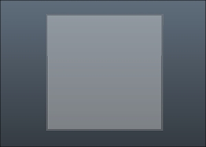
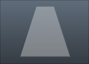
However, if you scale the proxies nonuniformly or change the primitive shape, the exporter may export it as a mesh proxy instead of a physics proxy, which is more expensive based on the resolution of that mesh. Check the following screenshots for examples.
The following screenshot shows a good capsule:
The following screenshot shows a bad capsule:
That being said, you can use the user defined property (UDP) to force a proxy to be a primitive in the engine. You can do that through the UDP window in the Crytek shelf. In the UDP window, you can simply type the primitive shape you want to convert your proxy to. You can choose between box, cylinder, capsule, and sphere:
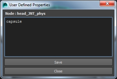
When you click on Save in the UDP window, a string attribute on the proxy is added with the typed value.
We will have a detailed look at the phys proxies and how to prepare them for the engine when we start creating them for the character in the next section.
In the Boris folder in Objects, you will find the boris_skeleton Maya file. The file has the character model and the deformation skeleton. The mesh is already bound to the skeleton and all we need is just to create the phys proxies now.
In the Polygons tab, go to Create | Polygon Primitives. To make it easier to go through the upcoming steps, turn off Interactive Creation and click on Cylinder.
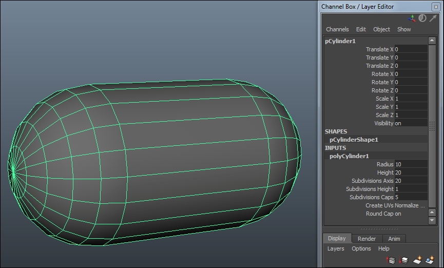
Now, we have a cylinder that we will use as a capsule for the left arm joint. To display the cylinder as a capsule in Maya, we will enable the Round Cap option in the PolyCylinder node of the cylinder shape in the channel box and increase the Subdivision Caps option to 5, as shown in the next screenshot.
Move, rotate, and scale (uniformly) the capsule to roughly match the shape of the upper arm. When you are happy, parent the capsule under the L_arm joint and rename it to L_arm_phys. All phys proxies need to have the name of the parent joint plus a suffix _phys.
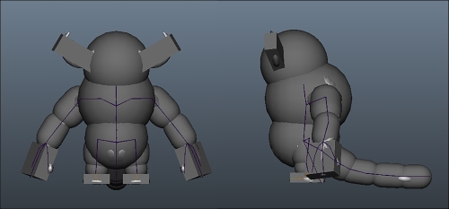
You can apply the same steps for the rest of the skeleton using cylinders as capsules or spheres or cubes. You don't need to create a capsule/phys proxy for every joint in the skeleton, just enough to cover the body mass of the character. The following screenshot shows an example of what your setup might look like. You can find the following setup in the boris_phys_skeleton Maya file in the Boris folder.
We are almost there; all we need now is to follow the next steps to apply a proxyNoDraw material to the phys proxies. The steps are as follows:
- Select all the phys proxies in the scene, and then right-click and select Assign New Material.
- Choose Blinn from the Assign New Material window.
- Rename the newly created Blinn material
boris_phys_mat. - While the material is selected, go to the Crytek shelf and click on Export.
- In Crytek Export window, click on the Add Attributes button.
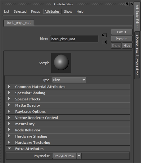
- Make sure you have the material selected and go to Attribute Editor.
- In the Extra Attributes section, set the Physicalize attribute to ProxyNoDraw.
As I have mentioned before, rigs can get very complex based on the character. For the sake of this book, we will stick to simplicity and stability. However, you can use the same concepts to rig any character no matter how complex it is—a biped, quadruped, or even a prop—and export it easily to CRYENGINE.
For your convenience, you should hide the phys proxies so you can easily see and select the joints. You should also enable X-Ray Joints from the shading menu in the view port so that you can see the joints inside the mesh.
We talked briefly about the animation skeleton in the Authoring the deformation skeleton in Maya section. The animation skeleton will give you more freedom in the hierarchy versus the deformation skeleton. For example, we can have other transform nodes besides the joints, such as locators or empty groups in the animation skeleton hierarchy, but we can't do that with the deformation skeleton because the exporter will throw errors about those nodes.
The easiest way to create the animation skeleton is to duplicate the deformation skeleton and give it a prefix. Select the root joint in the outliner and go to Edit | Duplicate, or use the shortcut Ctrl + D. Make sure to remove the duplicate phys proxies from the new skeleton.
To add the prefix, select the duplicate skeleton, go to Modify | Prefix Hierarchy Names, and type ANM_.
In the outliner, select the ANM_root joint first and then select the root joint. Make sure to be in the Animation menu set and go to Constrain | Parent. This will constrain the root joint position and orientation to the ANM_root joint position and orientation.
Repeat the same steps for every joint in the animation and deformation skeletons.
Now that we have the animation skeleton driving the deformation skeleton, you can save the file as boris_rig_ready in the Boris folder.
It is preferable to use controllers for selecting and posing the joint chain rather than the joints themselves. These controllers control our rig via constraints or direct parenting. Before we create our first controller, go to Create | NURBS Primitives | Interactive Creation and make sure this option is OFF.
We will use a nurbs circle for the shape of our controller. To create the circle, go to Create | NURBS Primitives | Circle. In the shape inputs in the channel box, you will find the makeNurbCircle1 node. This node controls the shape attributes of the circle, such as the radius, the normal direction, and the degree.
After you tweak the shape, to go to Edit | Delete by Type | History. This will delete our makeNurbCircle node, as the rig (depending on its complexity) can get heavy if we left that node for every controller in the scene.
Now, we need to align the controller to the object we will control. A fast way to do this is to simply create orient and point constraints from the object to the controller, and then delete the constraints.
Let's quickly create an object as a target to explain what we have been talking about here. Create a polygon Cube and rename it to targetCube. In the channel box, set Translate Z (up) to 10 and the Rotate X to 45.
Rename the nurbs circle to targetCube_CTRL. Select targetCube and targetCube_CTRL in that specific order, and make sure you are in the Animations menu set. Go to Constrain | Point | Options (the little square next to Point) and make sure Maintain Offset is OFF. Repeat the same steps as before, but now choose Orient instead of Point. You can see that targetCube_CTRL is aligned in position and rotation to targetCube and also constrained to it.
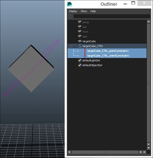
Now that we have our proper alignment for the controller, we can get rid of the point and orient constraints. You can find them in the outliner under the targetCube_Ctrl transform node, as shown in the following screenshot:
The last step we need to do before we create the connection between the controller and the target is to zero out the controller's channels. Animators are used to just zero out the channels on the controllers to go to the default pose, and it is really recommended to have that as a standard on all of your controllers.
Currently, we have values on the Translate Z and the Rotate X channels of our controller. To get rid of these values and at the same time retain the position and the orientation on the controller, we will create an offset group.
To create the offset group, make sure nothing is selected in the scene and create an empty group either by going to Edit | Group or using the shortcut Ctrl + G. Rename the newly created null1 group targetCube_CTRL_offset.
Apply the same transformation values of our controller to the offset group, that is, 10 in the Translate Z channel and 45 in the Rotate X channel. Now if you parent targetCube_CTRL under the targetCube_CTRL_offset group, you will see that the channels on our controller are zeroed out.
Note
Some artists use freeze transformations to zero out the channels on a transform node. Freeze transformations is not really recommended because it resets the orientation to world, so the controller will not have the same orientation as the target object any more (if this is the desired behavior then by all means use freeze transformations). Also, it can cause problems later when you try to create more complex setups, and need to snap this controller to another one (such as what we usually do when switching from FK to IK setups).
Now that we have our controller ready, we can create any kind of connection between it and the target object. You can tell by now that this process can take some time and because we want to be consistent in creating our controllers for our character, we have a Python script to do the job for us very quickly.
Go to the accompanied website and extract the scripts zip folder contents to your Maya scripts folder. The default script path is Users<username>Documentsmayascripts.
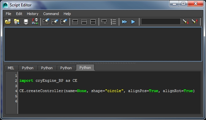
Let's try the script out! Go to Maya Script Editor by navigating to Window | General Editors | Script Editor. In the Script Editor window, go to the Command menu and select New Tab. A pop-up window will show and ask you to specify executer source language, choose Python.
In the Python tab, type in these lines of code:
import cryEngine_BP as CE
CE.createController(name=None, shape="circle", alignPos=True, alignRot=True, color="yellow)
This is shown in the following screenshot:
Now, we will go over these lines one by one.
import cryEngine_BP as CE
In the preceding line, we are importing our cryEngine_BP Python module that has all the functions we will be using in this chapter. The as keyword allows us to assign a shorter or more friendly name to our module. Consider the next line:
CE.createController(name=None, shape="circle", alignPos=True, alignRot=True)
Here, we are calling the createController function from the cryEngine_BP module, with some keyword arguments that we will go over one by one:
name: This argument is a string name for the controller we are creating. If the value isNone, then the controller name will be like the target object with a suffix of_CTRL, such as the naming convention we had for ourtargetCube_CTRL.shape: This argument tells thecreateControllerfunction what shape to create. We can choose betweencircle(which is the default value),arrow,star,cross,square, andarrowCircleas shapes for our controller.alignPos: This argument is a Boolean value to align the controller position to a target object.alignRot: This argument is a Boolean value to align the controller orientation to a target object.
There is a detailed description for the code inside the cryEngine_BP module, if you need to have a better look at the commands used to build this function. Now let's try to run our code.
Delete the targetCube_CTRL_offset group, then select the cube, and (while it is selected) execute the script in the Script Editor.
Now, you should have the same controller we created manually for targetCube.
Open the boris_rig_ready file in the Boris folder. Since we will be working mainly on the animation skeleton for this and upcoming sections, there is no need to see the deformation skeleton for now. To hide the deformation skeleton, we just need to hide the top parent node which is the Root bone.
For the arm, we will create a very simple FK rig. FK is short for forward kinematics. Forward kinematics provides a direct control over each joint rotation, which makes it easier for creating nice and clean arc motions.
To create the FK controllers, select the ANM_L_arm joint in the animation skeleton hierarchy; while the joint is selected, execute these lines of code in the same Python tab we created before:
CE.createController(name="L_arm_CTRL", shape="circle", alignPos=True, alignRot=True)
The only thing we changed here is the name of the controller. Repeat the same steps for ANM_L_elbow_JNT and change the name argument value in our createController function to L_elbow_CTRL. So it should look like this:
CE.createController(name="L_elbow_CTRL", shape="circle", alignPos=True, alignRot=True)
Repeat the same steps for ANM_L_hand_JNT, and change the name to L_hand_CTRL.
You probably cannot see the controllers because they are hidden inside our character's model. If you press 4 to enable the wireframe view, you will be able to see them inside the mesh, as shown in the next screenshot.
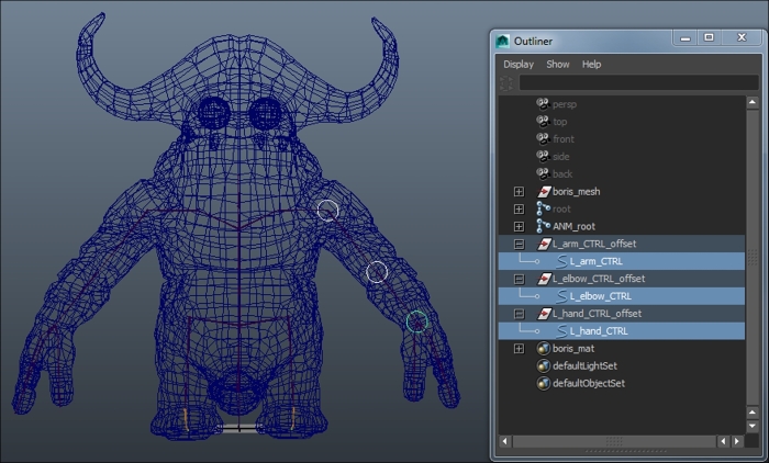
Repeat the same steps for all of the controllers' curves. When you are done, you can toggle back to object mode by pressing F8 again.
Now, we are ready to constrain the arm joints to the controllers via orient constraints. Select L_arm_CTRL followed by ANM_L_arm, make sure you are in the Animation menu set, and go to Constrain | Orient. Repeat the same steps to constrain ANM_L_elbow_JNT to L_elbow_CTRL and ANM_L_hand_JNT to L_hand_CTRL.
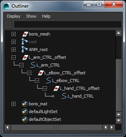
Our final step is to parent the controllers to each other accordingly. Parent the L_elbow_CTRL_offset group under L_arm_CTRL, and then parent the L_hand_CTRL_offset group to L_elbow_CTRL. The next screenshot shows what the arm controller hierarchy should look like:
You can look at each digit as an arm on its own. We will use the same setup we used before for the arm starting with the thumb.
Select the ANM_L_thumb_01_JNT joint and execute our createController function in the Script Editor to create a controller aligned in position and orientation to that joint. We will name our controller L_thumb_01_CTRL:
CE.createController(name="L_thumb_01_CTRL", shape="circle", alignPos=True, alignRot=True)
Repeat the same steps for the second and the third thumb knuckles. Remember to change the name to represent the number of the knuckle before the _CTRL suffix.
Now, you should have the L_thumb_01_CTRL, L_thumb_02_CTRL, and L_thumb_03_CTRL controllers for our thumb. As with what we did for rigging the arm, you should now create orient constraints to constrain the thumb joints to their corresponding controllers.
Parent the L_thumb_02_CTRL_offset group to L_thumb_01_CTRL and parent the L_thumb_03_CTRL_offset group to L_thumb_02_CTRL.
The final step in rigging the thumb is to parent the L_thumb_01_CTRL_offset group to L_hand_CTRL so that the thumb follows the movement of the hand.
Repeat the same process for the rest of the fingers and you should have your hand setup ready.
For the clavicle, we will use a pretty straightforward setup: just a simple controller!
Select the ANM_L_clavicle_JNT joint and create a controller called L_clavicle_CTRL aligned in position and rotation to the clavicle joint. We will also use the arrow shape this time for the controller. This is what the createController function should look like:
CE.createController(name="L_clavicle_CTRL", shape="arrow", alignPos=True, alignRot=True)
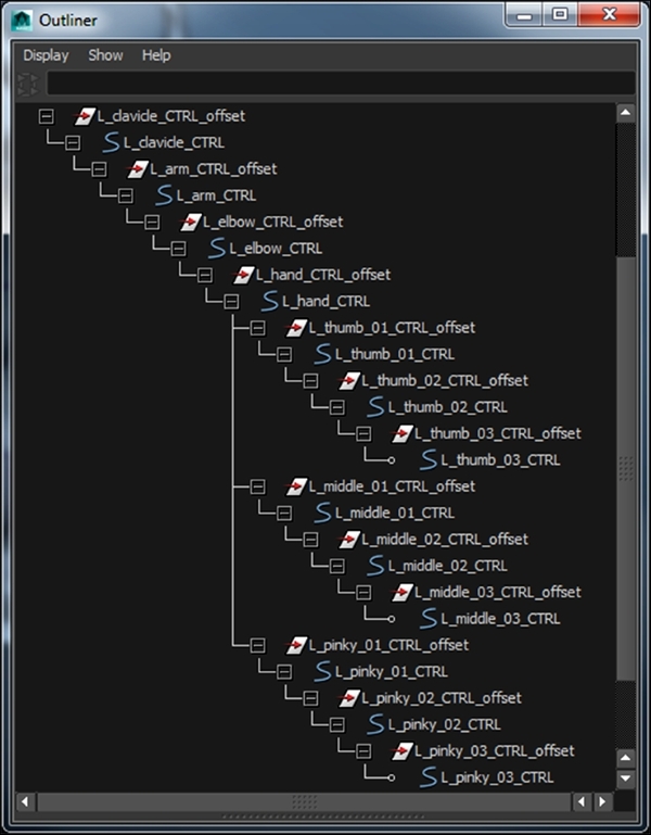
Create an orient constraint to connect ANM_L_clavicle_JNT to our clavicle controller. Now, we can parent our L_arm_CTRL_offset group to L_clavicle_CTRL so that our arm and hand rigs follow the clavicle motion. The next screenshot shows what the controller hierarchy should look like in the outliner:
Now that we have all of our arm, fingers, and clavicle controllers in the scene and parented in the right order, we should now lock and hide all the channels that we will not use for these controllers.
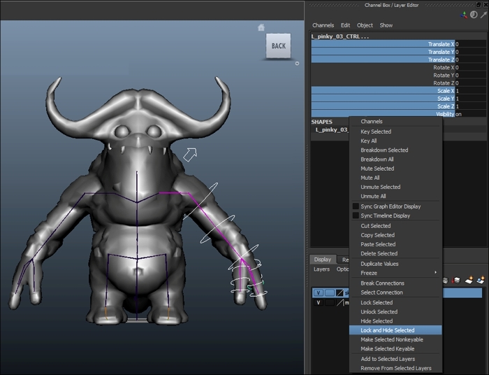
Since we used only the forward kinematics setup for our arm rig so far, we don't need to keep any translation channels on the controllers (unless you intentionally want to break the joints). We should also hide and lock the scale and the visibility channels for all the controllers that we have for the whole rig.
To lock and hide those channels, select all the arm, fingers, and clavicle controllers. In the channel box, select the translation, scale, and visibility channels, and then right- click and select Lock and Hide Selected. This is shown in the next screenshot:
If you analyze where the most action of the spine happens, you will find it mainly happens in the chest and the hip areas. Ideally, we would like to pose these two areas separately without them affecting each other but at the same time we have that smooth interpolation on all the joints between them.
There are many ways to rig the spine. In our case, we will simply create our two main controllers for the hips and the chest and average the position of the rest of the joints between them.
To create the chest controller, select the ANM_spine_03_JNT joint and run our createController function to create a controller named chest_CTRL, which is aligned in position to the joint:
CE.createController(name="chest_CTRL", shape="square", alignPos=True, alignRot=False)
Parent-constrain the joint to our new controller, and make sure in the parent constraint options to enable Maintain Offset.
To create the controller for the hips, select ANM_spine_01_JNT joint and create a controller named hips_CTRL that is also aligned only in position to the joint. Use our createController function.
After you create the controller, create a parent constraint with Maintain Offset set to on to constrain the ANM_spine_01_JNT joint to the hips_CTRL controller. We also need to constrain ANM_pelvis_JNT to hips_CTRL using another parent constraint with Maintain Offset set to on so that it follows the controller's movement.
Now that we have our two main controllers for the spine, it is time to take care of the joints in-between. In order to be able to average the position of the middle joint between both controllers and achieve that natural twist when we rotate one of them about its aim axis (in our case z), we will need to use a little bit of advanced rigging methods. It's nothing complicated, I promise.
Let's start with averaging the position of ANM_spine_02_JNT between the chest and the hips controllers in the next few steps:
- Create three locators with the following names: ANM_spine_02_LOC, ANM_spine_02_UP and ANM_spine_02_AIM.
- Move the ANM_spine_02_UP locator 25 units in the x axis.
- Parent ANM_spine_02_UP and ANM_spine_02_AIM under ANM_spine_02_LOC, as shown in the following screenshot:
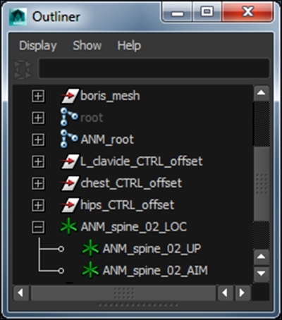
- Snap ANM_spine_02_LOC to the ANM_spine_01_JNT joint position.
Note
You can snap one object to another using the temporary point constraint technique we explained before in the Creating the controllers section. Alternatively, while using the Move tool, hold V (shortcut for the Snap to Points tool), click on the middle mouse button, and move to the object you want to snap to.
- We will use these locators to control the ANM_spine_02_JNT joint. Create a parent constraint with Maintain Offset set to on from the ANM_spine_02_AIM locator to the ANM_spine_02_JNT joint. Now if you move and rotate the top locator ANM_spine_02_LOC, you will see that our joint is following.
- Finally, select chest_CTRL, hips_CTRL, and ANM_spine_02_LOC (in that order) and create a parent constraint with Maintain Offset.
Now if you move the chest or the hips controller, you will see that the position of the middle joint is averaged between both of them. However, in order to get that smooth line between the hips and chest, we also need to make the spine joints aim towards each other and we should also be able to twist like a normal spine. We can get this result using the aim constraint.
The aim constraint constrains an object's orientation so that it aims at other object/objects. To create an aim constraint, we need to provide three vectors: the aim vector, the up vector, and the world up vector. The aim vector is the constrained object's local axis that you want to aim towards the target object. The twist orientation of the object is controlled by the up vector and the world up vector. Please refer to the Maya documentation at http://help.autodesk.com/view/MAYAUL/2015/ENU/? if you need more information about the aim constraint.
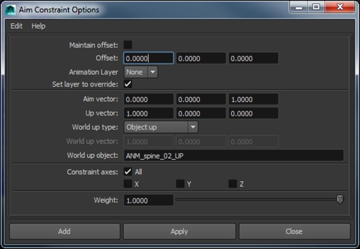
Let's see how we can use all of this information to achieve the result we want. Select chest_CTRL and then the ANM_spine_02_AIM locator, and go to Constrain | Aim Constraint Options. In the Aim Constraint Options window, apply the following settings:
In the options box, we used the Aim vector field to tell the aim constraint to constrain our ANM_spine_02_AIM locator's positive z axis to point to our chest_CTRL. In the Up vector field, we decided to use the ANM_spine_02_AIM locator's positive x axis as it's up vector. In the World up object field, we tell our up vector to try to point in the same direction as the ANM_spine_02_UP locator.
If you move the ANM_spine_02_UP locator in the y axis now, you should see that it is controlling our ANM_spine_02_JNT joint, and if you move and rotate the chest_CTRL, the ANM_spine_02_JNT joint is aiming to it and twisting properly.
We are almost there! The final step for that setup is to also make our ANM_spine_01_JNT joint aim towards our mid spine joint too. To do this, we will repeat some of the steps we followed before.
Duplicate ANM_spine_02_LOC and replace spine_02 in the name of the duplicate locator and its children with spine_01. Snap ANM_spine_01_LOC to the position of the ANM_spine_01_JNT joint and parent it under hips_CTRL. Delete the parent constraint we created before on ANM_spine_01_JNT and create a new parent constraint with Maintain Offset set to on to constrain ANM_spine_01_JNT to the ANM_spine_01_AIM locator.
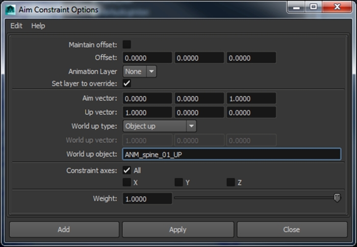
Now, we will create an aim constraint to constrain the positive z axis of the ANM_spine_01_AIM locator to point towards the ANM_spine_02_LOC locator. Select ANM_spine_02_LOC, select the ANM_spine_01_AIM locator, and go to the Aim Constraint Options window to apply these settings:
Now, we have our spine rigged and our controllers aiming towards each other properly. The advantage of this setup, besides the flexibility, is you can also squash and stretch without creating any problems exporting because we are relying on translation only.
Besides the hips and the chest controllers, we will need another controller we can use to move and rotate the whole upper body. We will use our createController function to create a controller aligned in position to the ANM_pelvis_JNT joint and name it upperBody_CTRL:
CE.createController(name="upperBody_CTRL", shape="arrowCircle", alignPos=True, alignRot=False)
Tweak the shape of the new controller so that it is visible and selectable. Then, parent the hips_CTRL_offset and chest_CTRL_offset groups and the ANM_spine_02_LOC locator under upperBody_CTRL.
Now if you move upperBody_CTRL, you will see the whole body is following. If you rotate it, you will notice the clavicle and the arm are not following the body orientation. To fix this, we need to parent the L_clavicle_CTRL_offset group under our chest_CTRL. Now when we rotate the upper body controller, the whole body is moving and orienting as it should.
For the head and the neck joints, we will use simple FK controllers. Select the ANM_neck_JNT joint and run our createController function with the following parameters:
CE.createController(name="neck_CTRL", shape="circle", alignPos=True, alignRot=False)
Create a parent constraint with Maintain Offset set to on to constrain the ANM_neck_JNT to the neck_CTRL controller.
We will do the same for the head joint, just change the name of the controller to head_CTRL. Select the ANM_head_JNT joint and run the createConntroller function:
CE.createController(name="head_CTRL", shape="circle", alignPos=True, alignRot=False)
We will also use a parent constraint with Maintain Offset to connect the ANM_head_JNT joint to our head controller. Now, parent the head_CTRL_offset group under neck_CTRL and parent the neck_CTRL_offset group under our chest_CTRL so everything now follows the upper body controller and our neck and head controllers follow our chest controller.
So far, we should be able to move and rotate all the spine and head controllers. We just need to lock and hide all the scale and visibility channels on the controllers in the channel box, as we did before for our arm controllers (check the Cleaning up the arm controllers section). It is worth mentioning that you should also lock and hide the channels on the rigging locators we used for the spine, since we don't want the animators or yourself to select or delete them by mistake.
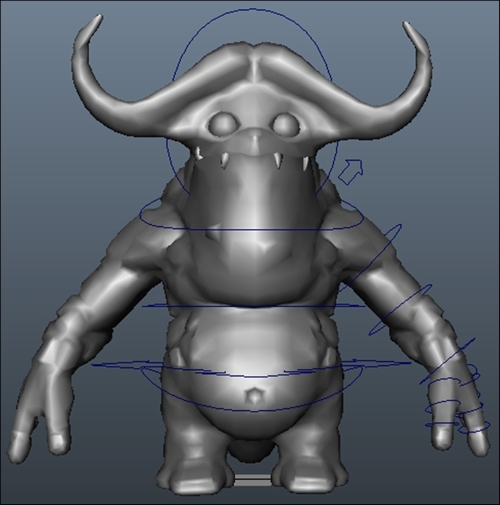
This is a screenshot of what the setup of the upper body can look like with some tweaking on the controllers shape:
It can get a little difficult to use the FK to pose the legs against the upper body. So, we will use inverse kinematics (IK) to rig the legs. When you move an IK handle, the solver calculates the rotations of all the joints between the start joint and the end joint based on the position of the end effector that is usually located at the end joint.
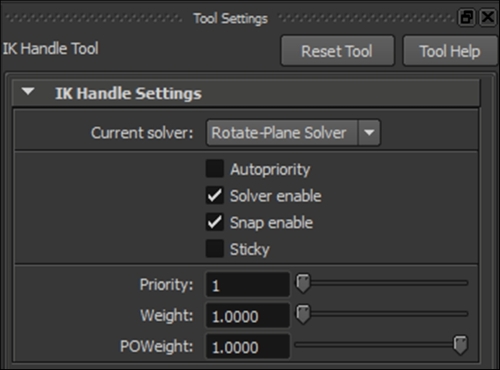
There are different types of IK solvers that are available in Maya. The most common one used for rigging the limbs is the Rotate-Plane IK solver (ikRPsolver). Please refer to the Maya documentation at http://help.autodesk.com/view/MAYAUL/2015/ENU/?guid=CSN_ikHandle for more information about the IK solvers available in Maya.
To apply the IK handle to our leg joints, go to Animation | Skeleton | IK Handle Tool. In the Tool Settings window, select Rotate-Plane Solver for the Current solver option, as shown here:
Click on our start joint ANM_L_thigh and then click on our end joint ANM_L_ankle_JNT. You should see our new IK handle in the outliner; rename it as L_leg_IKH. If you start moving the IK handle, you will see how it drives the rotation of our IK chain. We don't want to select the IK handle to move our joints, so we will use the createController function to create a controller for that. Select the ANM_L_ankle_JNT joint and run the function with the following parameters:
CE.createController(name="L_foot_CTRL", shape="square", alignPos=True, alignRot=False)
Now that we have a controller for our IK handle, we just need to create the connections so we are able to pose the leg only using L_foot_CTRL. Create a point constraint to constrain the position of L_leg_IKH to our foot controller and then create an orient constraint with Maintain Offset set to on to constrain the orientation of the ANM_L_ankle_JNT joint to the controller.
To control the twist of the joint chain, we need to create a pole vector controller for the IK handle. To do so, select the ANM_L_knee_JNT joint and run our createController function:
CE.createController(name="L_leg_PV_CTRL", shape="star", alignPos=True, alignRot=False)
This will create a star-shaped controller positioned exactly at the knee joint. Select the L_leg_PV_CTRL_offset group and move it an additional 40 units in the y axis, so that the controller is out of the mesh and in front of the knee joint.
Select L_leg_PV_CTRL, select the L_leg_IKH, and go to Constrain | Pole Vector. This will create a pole vector constraint on the IK handle, so we can control the twist or the orientation of our joint chain with L_leg_PV_CTRL.
It is important to mention that if the L_leg_IKH crosses our pole vector controller or faces the opposite direction, the leg joints can flip. To fix this, we can simply move the pole vector controller so it is always in front of the leg.
The last step to finish our leg rig is to create a toe controller. You can simply create the L_toe_CTRL controller that is aligned in position and orientation to the ANM_L_toe_JNT joint using the createController function. Then, create an orient constraint to connect the ANM_L_toe_JNT joint to the controller.
Parent the L_toe_CTRL_offset group under the L_foot_CTRL controller so that it follows the leg movement.
Select all the controllers we created for the leg, and then lock and hide the scale and visibility channels from the channel box. We will not need to rotate the pole vector controller, so lock and hide the rotation channels on L_leg_PV_CTRL. For the toe controller, you should lock and hide the translation channels (unless you want to break the toe).
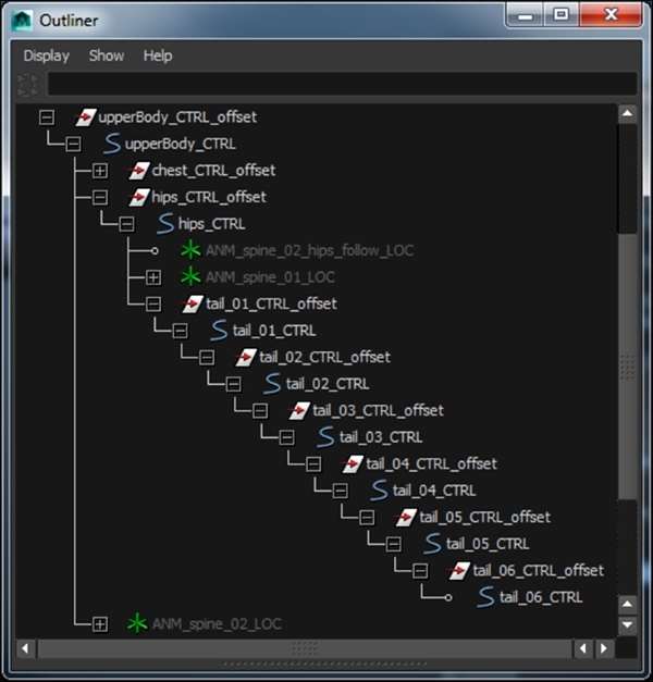
We will create a very simple FK setup for the tail. You should be familiar with the process now. Starting with the first joint of the tail, select the ANM_tail_01_JNT joint and run the createController function:
CE.createController(name="tail_01_CTRL", shape="circle", alignPos=True, alignRot=True)
Then, create an orient constraint to constrain the ANM_tail_01_JNT joint to the tail_01_CTRL controller. Repeat the same steps for every joint in the tail, parent the offset groups of the child controllers to their preceding controller, and parent the tail_01_CTRL offset group under the hips_CTRL controller so the tail follows the hips movement. This is what the hierarchy for the tail controllers should look like:
You can do lots of stuff to enhance the deformations on this character. Armored with the knowledge of the do's and the don'ts for rigging a character to export to CRYENGINE, you can now freely be creative to correct some of the deformations on this character. For the purpose of this chapter, we will keep things simple and merely talk about fixing the twist on the upper and the lower arm.
If you take a look at any reference material for how the forearm moves around, you will notice that when the wrist twists, it occurs down the entire length of the forearm. The forearm is made up of two joints the radius and the ulna, and during pronation the distal end of the radius rotates around the ulna from its position on the lateral side of the wrist to the medial side of the wrist. This action turns the hand, wrist, and forearm almost 180 degrees.
You can achieve this kind of behavior with different methods, such as using the spline IK in Maya to drive a twist chain or utility nodes to directly distribute the twist value along the forearm joints.
Using a similar technique we used for rigging the spine, we will use the aim constraint to drive the twist on our ANM_L_hand_twist_JNT joint. To average the twist between the hand and the elbow joints, we will need to create three locators.
Create a locator with the same position and orientation as the ANM_L_hand_JNT joint. Rename the locator L_hand_twist_UP and parent it under the L_elbow_CTRL controller.
Move the locator about 20 units in Translate Y, then duplicate it twice. Rename the first duplicate locator L_hand_twist_elbow_follow_LOC and rename the second duplicate locator L_hand_twist_hand_follow_LOC. Parent the L_hand_twist_hand_follow_LOC locator under the L_hand_CTRL controller.
Select both the L_hand_twist_elbow_follow_LOC and L_hand_twist_hand_follow_LOC locators, parent the L_hand_twist_UP locator, and create a parent constraint. This will average the position and orientation of the L_hand_twist_UP between the hand and the elbow joints.
Select the ANM_L_hand_JNT joint, select the ANM_L_hand_twist_JNT joint, and go to the Aim Constraint Options window to apply the following settings:
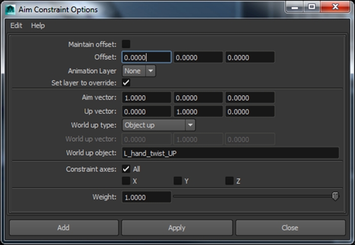
Now, the twist rotation of the ANM_L_hand_JNT joint is controlled by the L_hand_twist_UP locator and averaged between the hand and the elbow joints. To keep the scene clean, hide all the locators we have created and lock their channels since we don't want to move or delete them by mistake.
If you look at a reference or yourself when you twist your arm, the shoulder bone itself doesn't rotate. Instead, the effect takes place gradually down the length of the arm.
To achieve that kind of twist behavior, we need to lock the first upper arm twist joint so it doesn't rotate when we use our FK controller for twisting the arm.
We will need to create a set of locators to achieve that kind of setup for the upper arm. Create an empty group and name it L_upperarm_offset_GRP. Align the group's position and orientation to the ANM_L_arm joint. Create a locator, name it L_upperarm_driver_LOC, and parent it under the L_upperarm_offset_GRP group. Zero out all the translation and rotation channels on the L_upperarm_driver_LOC locator so that it is snapped to its parent group.
Duplicate the L_upperarm_driver_LOC locator and rename it L_upperarm_aim_LOC. Move the new locator about 5 units along its local x axis.
Duplicate L_upperarm_driver_LOC locator twice and rename the first duplicate L_upperarm_lock_LOC and the second one L_upperarm_twist_LOC. Parent L_upperarm_twist_LOC under the L_upperarm_lock_LOC locator.
We will use L_upperarm_aim_LOC to lock the twist axis on the L_upperarm_lock_LOC locator using an aim constraint. Select L_upperarm_aim_LOC, select L_upperarm_lock_LOC, and go to the Aim Constraint Options window to apply the settings shown in the next screenshot.
The L_upperarm_twist_LOC locator will be used to extract the proper twist value to be used on the upper arm middle twist joint. By adding an orient constraint from the L_upperarm_driver_LOC locator to the L_upperarm_twist_LOC, we will get the rotation difference between L_upperarm_driver_LOC and the L_upperarm_lock_LOC locators.
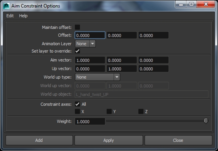
Setting World up type to None in the Aim Constraint Options window will orient L_upperarm_lock_LOC such that the aim vector points to the L_upperarm_aim_LOC world position, but no twist calculation is performed by the constraint.
Now, we need to connect our locators' setup to the left arm rig. Start by parenting the L_upperarm_offset_GRP group under L_clavicle_CTRL. Create a parent constraint to constrain the L_upperarm_driver_LOC locator to the ANM_L_arm joint. To lock the twist on the first arm joint, orient-constrain the ANM_L_arm_twist_01_JNT joint to L_upperarm_lock_LOC.
Now if we rotate the L_arm_CTRL controller, the ANM_L_arm_twist_01_JNT joint follows in every axis except the x axis, which is exactly what we wanted. The last step in our upper arm twist setup is to distribute the twist on the middle twist joint ANM_L_arm_twist_02_JNT. Select both L_upperarm_lock_LOC and L_upperarm_twist_LOC, select ANM_L_arm_twist_02_JNT, and create an orient constraint.
Now that we have all the rig components ready, we just need to create the last controller for this rig: Locomotion_CTRL. Select the ANM_root joint and run our createController function:
CE.createController(name="locomotion_CTRL", shape="arrow", alignPos=True, alignRot=True)
Create a parent constraint to connect the ANM_root joint to Locomotion_CTRL. This controller is used in the engine to describe the logical movement and orientation of the animation.
It is recommended that you organize the rig into groups. You can have one group for the controllers and another one for the joints in the scene, and use a group on top of both to globally move the rig. Keep in mind that you can't have the skinned meshes in the same group as the group you will use to move the rig; otherwise, you will have double transformations. Have a look at the final rig structure in the boris_rig.ma file in the Boris folder.
As mentioned before, this chapter is not meant to teach you everything about rigging. However, we covered very important concepts to create a very light and stable rig that is also compatible with CRYENGINE. There are many additions you can explore on your own to add to the rig if you want to take it to the next level, for example, a reverse foot setup and IK FK switch.