
CHAPTER 3
Analog and Digital Signals
In this chapter, you will learn about
• The difference between analog and digital waveforms
• Digital signal processing, sampling, bit depths, and bit rates
• Signal compression and digital formats
• Noise and signal transmission
The technology that supports much of the AV industry is making a transition from analog transmission, recording, and processing to digital. Why is this important? In the AV industry, you will work with some analog equipment, more digital equipment, and some equipment that combines analog and digital. You need to understand both technologies.
Analog and Digital Waveforms
One way to understand analog signals is to create a mental image. Think of a dimmer light switch, which offers a continuous range of positions between off and full brightness. Information about the brightness setting can be represented by a signal that varies in direct relation with the position of the dimmer knob. This is analog data, so named because it is analogous to a variable physical quantity. Analog information is usually transmitted and stored as a continuous and varying waveform, directly related to a physical quantity such as sound pressure or image brightness.
However, digital information requires a different mental image. Think of an overhead fan controller that offers only set speeds between off and maximum. You can select speed 1, speed 2, speed 3, etc., but no speeds in between. In the digital world, varying signals are represented by a series of numbers based on the signal level at particular times. In electronic systems, those numbers are stored and transmitted as streams of binary digits (1s and 0s), where the signal is either a one (on) or a zero (off).
Figure 3-1 shows the difference between analog and digital waves. Figure 3-1 shows two characteristics of an analog waveform. The first characteristic is the constantly flowing line. The second characteristic is the changing amplitude over time. Digital information is represented by sequences of the numbers 1 and 0. In a digital waveform, the wave looks like a series of rectangles where the voltage rapidly swings between either high-voltage (on) or low-voltage (off) states.
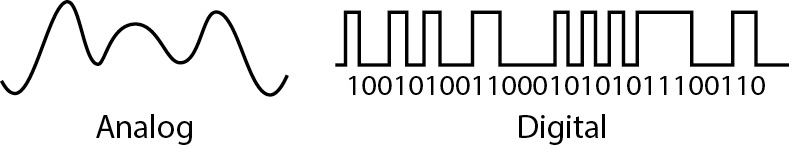
Figure 3-1 Analog signals are continuous, while digital signals are either on or off.
Digital Signal Basics
As noted at the beginning of the chapter, AV technology has moved from being mostly analog to predominantly digital. AV professionals need to know about digital signal processing, sampling, bit depths, and bit rates. They also need an understanding of signal compression and digital formats.
Digital Signal Processing and Sampling
Many inputs to AV systems arrive in analog form, such as sound pressure waves impacting a microphone diaphragm, pressure from a finger touching a tablet, or light focused onto a camera sensor. To transmit, process, or record these inputs in digital AV systems, the signals need to be converted into digital formats. You may also have archived analog material or older equipment with analog outputs that you need to incorporate into digital streams and systems.
The goal of any analog to digital conversion process is to create an accurate digital representation of the original analog signal. The first step is to take an accurate snapshot of the level of the analog waveform at a particular time, a process known as sampling. That sampled level is then converted into a binary numeric value in the digitization process.
To track the variations in an analog signal, samples need to be taken at regular intervals. How often samples are taken is called the sampling rate, which is usually measured in hertz (samples per second). Determining an acceptable sampling rate is crucial to obtaining a digital representation that resembles the original signal.
From the world of information theory, the Nyquist–Shannon sampling theorem tells us that an analog signal can be reconstructed if it is encoded using a sampling rate that is greater than twice the highest frequency being sampled, as shown in Figure 3-2. For example, if we want to accurately sample audible sounds that occur in the frequency range from 20Hz to 20kHz, then the sampling rate should be higher than 40kHz. In the traditional audio CD, the sampling rate is 44.1kHz, which means that 44,100 samples are taken of each of the two incoming audio streams every second. The audio on Blu-ray movie recordings is commonly sampled at 48kHz, 96kHz, or 192kHz.
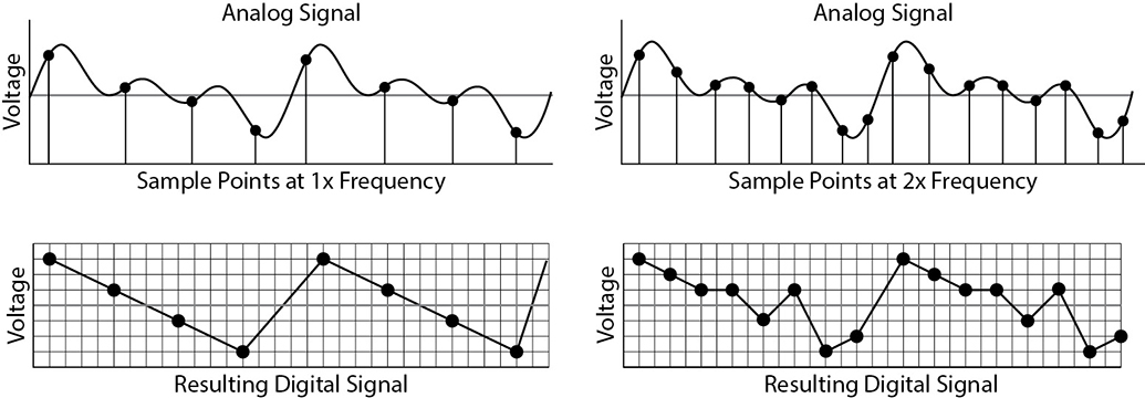
Figure 3-2 Sampling at twice the frequency results in a more accurate digital representation.
The two images in Figure 3-3 show the differences between an analog signal and a digital sample of the analog signal. The analog signal is on the right. Notice how there is a smooth transition from white at the top to black at the bottom. The image on the left represents the digital sample of the analog image. Notice that the image appears to be made of four different blocks, or four samples.
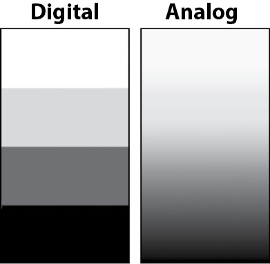
Figure 3-3 A digital representation of an analog image
Bit Depth of a Digital Signal
The sampling rate determines the digital signal’s accuracy (how closely it captures the frequency of the original signal). The precision (how close the converted digital value is to the analog sample’s amplitude) is determined by the digitizer’s bit depth.
Bit depth is defined as the number of states you have in which to describe the sampled voltage level. If you have 1 bit, whose value can be 0 or 1, you can describe the signal as being only on or off (two states). If you have 2 bits, you have four possible states (00, 01, 10, or 11) in which to describe a signal. A bit depth of 3 bits will have eight possible states.
As the number of bits increases, the number of possible states increases exponentially. In fact, the number of possible states increases by 2 to the power of the number of bits. A bit depth of 16 will have 65,536 (216) possible states to describe the signal. Standard audio CD resolution is 16 bits.
Bit depth in digital video signals is a measurement of how many shades can be displayed. Each possible color is a state. The greater the bit depth, the more realistic the image will look. A black-and-white display is called 1-bit because it allows only two states (black and white), which is 2 to the power of 1. A 16-color display is called 4-bit because this is 2 to the power of 4. The next level is 256 colors, which is 2 to the power of 8, or 8-bit, and so forth.
Figure 3-4 shows a 4-bit grayscale displaying all 16 potential shades. Table 3-1 lists the bit depths and the number of potential states.

Table 3-1 Bit Depths and the Number of Potential States

Figure 3-4 A 4-bit grayscale showing all 16 potential states
Bit Rate
Bit rate is a measurement of the flow of information over time in a digital signal stream. It is measured using bits per second (bit/s or bps). The standard multipliers of kilo (k) = 103, mega (M) = 106, and giga (G) = 109 are used with this unit. Generally speaking, the higher the bit rate, the higher the accuracy of the signal.
Bit rate is calculated by multiplying the sample rate by the bit depth. In the case of stereo CD audio, the sample rate is 44.1kHz and the bit depth is 16 bits for each channel (44,100 × 16 × 2)—a bit rate of 1.411Mbps.
In some circumstances, data transfer rates are stated in bytes per second (Bps—note the uppercase B), which can be confusing. A byte is a block of eight bits used for representing symbols, numbers, and text in many data processing applications.
To convert bytes per second (Bps) to bits per second (bps), use this calculation:
![]()
Table 3-2 lists the bit rates of several common data formats. As you can see, the bit rate for UHD 4k video is much higher than the bit rate for an audio CD. This means that if you want to send a UHD 4k signal from one location to another, you will need a lot more bandwidth.
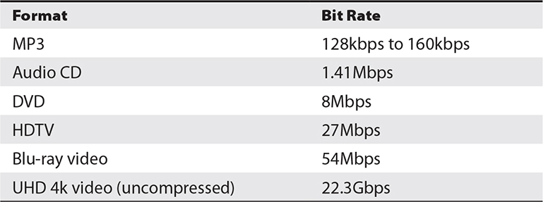
Table 3-2 Some Common Formats and Their Required Bit Rates

NOTE Watch carefully for Bps versus bps when reading or specifying data rates.
Signal Compression
Compression allows us to reduce the size of a data stream or file. Simple compression processes take advantage of repeated data patterns in a signal or file to reduce the number of times the pattern is stored or transmitted. The original signal can later be mathematically reconstructed to its original size and pattern without any loss of accuracy. This is known as lossless compression and can work well in compressing text, music, and video streams, although the amount of compression can be relatively low. ZIP, FLAC, MPEG-2, PNG, and JPEG2000 are some examples of efficient lossless compression methods. Only lossless compression techniques are considered to be acceptable for critically accurate applications such as text transmission and financial transactions.
Advanced compression processes are based on the human brain’s inability to perceive all of the available detail in an image or a sound, and they use a variety of signal processing techniques to reduce the amount of unnoticeable detail transmitted or stored. This is known as lossy compression and can be almost undetectable at moderate compression levels, although the lack of fidelity becomes quite noticeable at high compression levels. MP3, JPEG, HEVC, and H.264 (aka AVC) are examples of high-efficiency lossy compression methods.
For example, a single frame of uncompressed HD video at a resolution of 1920 × 1080 pixels, with 3 × 8-bit color samples per pixel, requires about 6.2MB of storage. At 30 frames per second, that’s about 11GB per minute of storage, or a 1.5Gbps video stream. Using H.264 compression, Internet streaming services are delivering HD video over just 5Mbps of bandwidth, which represents a compression ratio of about 300:1. However, as this is lossy compression, it’s not as sharp or vivid as the original but is considered acceptable on a small screen. As the mathematical techniques for data compression are under constant development, you can expect compression ratios to continue to improve with little, if any, additional loss of fidelity.
The critical steps in the compression process are analyzing and encoding the digital data to reduce its size, and later decoding the compressed data into its original format. The devices and software processes that perform these functions are known as codecs, a witty combination of the terms coder and decoder.
To achieve an optimum level of data compression, while also reducing the complexity of the decoding process, encoding often involves complex signal analysis, pattern detection, and intensive computation—a feat not always possible in real time. This can lead to substantial signal delay in a streaming system pipeline or a pause between recording an uncompressed signal and replaying it in its compressed form. Specialized codec systems have been developed for audio and video streaming, video conferencing, video recording, and post-production.
Digital Media Formats
A digital media file contains two elements.
• Container The container (such as AVI, which stands for Audio Video Interleaved) is the structure of the file where the data is stored. The container holds the metadata (data about the data) describing how the data is arranged and which codecs are used.
• Codec The codec provides the method for encoding (compressing) and decoding (decompressing) the file. Many video and audio codecs are in use today, with new ones constantly being created. In some cases, the codec must be installed in the operating system to play the file.
Some sophisticated replay applications such as the multiplatform, open source VLC media player can decode a wide variety of media file formats. Many applications and online services are available for converting media files between formats.
Formats can be confusing because the term codec is used interchangeably to describe the container and the codecs used within the container. In addition, some codec names describe both a codec and a container. An AVI container, for instance, could contain data encoded with an MPEG codec.
Noise and Signal Transmission
Analog signals are challenging to transport from one place to another. Consider the largest audio system there is: the legacy copper-wire telephone system. To carry the audio signal corresponding to a human voice from city to city, the signal may need to be boosted with repeater amplifiers many times along its journey to overcome the losses found in cable and switching systems. Every time you re-amplify a signal, you also amplify the noise and distortion introduced by cables and processing in the network, as illustrated in Figure 3-5. After many generations of re-amplification, the signal becomes indistinguishable from the noise.

Figure 3-5 Distance and noise degrade analog signal quality.
Digital signals are not affected by noise in the same way as analog signals. As noise is introduced to a digital signal, simple processing circuitry can determine whether the signal is intended to be either high or low and then retransmit a clean digital signal without the imposed noise, as illustrated in Figure 3-6.

Figure 3-6 Effects of degradation on a digital signal
Analog and Digital Signal Considerations
One major problem with analog signals is that they are subject to the noise generated by every cable, connector, and processing device in the signal chain. If anything happens to analog media after recording (tapes warp and stretch, discs get scratched, oxide is shed from tapes), the signal retrieved from the media will not closely match what was originally recorded. When making copies of an analog recording, the noise introduced during replication will increase with each sequential generation. After several generations of copies, the file quality may become unacceptable.
Duplicating a digital signal is essentially replicating a list of numbers. When copies are made of a digital recording, the quality of each copy is indistinguishable from the original. You can replay a digital recording many times, and provided that the recording medium is not physically damaged, the quality will remain the same.
Chapter Review
When it comes to professional AV, CTS candidates must be prepared to work in what was once an all-analog world as it rapidly transitions to digital. Analog and digital waveforms are fundamentally different, and those differences help dictate how AV pros design the systems that create, process, transport, manage, store, and play back analog and digital media.
Review Questions
The following review questions are not CTS exam questions, nor are they CTS practice exam questions. Material covered in Part II of this book provides foundational knowledge of the technology behind AV systems, but it does not map directly to the duties/tasks covered on the CTS exam. These questions may resemble questions that could appear on the CTS exam but may also cover material the exam does not. They are included here to help reinforce what you’ve learned in this chapter. See Appendix D for more information on how to access the online sample test questions.
1. In a digital signal, the on state is represented by _____, and the off state is represented by ____.
A. Two; one
B. One; two
C. Zero; one
D. One; zero
2. A signal that has many varying states is called a(n) _____ signal.
A. Analog
B. Fluctuating
C. Dimmer
D. Digital
3. Bit depth is defined as the number of _____ you have in which to describe the value.
A. Signals
B. Speeds
C. States
D. Rates
4. Lossy compression is particularly suitable for the transmission of _______.
A. Spreadsheets
B. Text files
C. Financial data
D. Audio, video, and images
5. What is a codec?
A. A structure of data containment
B. A formatting system
C. A program that holds data
D. A device or processing system that encodes and decodes data
6. As noise is introduced along a(n) _____ signal path, processing circuitry can determine whether the signal is intended to be high or low and then retransmit a solid signal without the imposed noise.
A. Digital
B. Dirty
C. Analog
D. Clean
7. Noise overcomes the signal after many generations of re-amplification of a(n) _____ signal.
A. Digital
B. Analog
C. Low
D. High
Answers
1. D. In a digital signal, the on state is represented by one, and the off state is represented by zero.
2. A. A signal that has many varying states is an analog signal.
3. C. Bit depth is defined as the number of states you have in which to describe the value.
4. D. Lossy compression is particularly suitable for the transmission of audio, video, and images.
5. D. A codec is a device or processing system that encodes and decodes data.
6. A. As noise is introduced along a digital signal path, processing circuitry can determine whether the signal is intended to be high or low and then retransmit a solid signal without the imposed noise.
7. B. Noise overcomes the signal after many generations of re-amplification of an analog signal.