CHAPTER 6
Networks
In this chapter, you will learn about
• The types and topologies of networks
• Ethernet and the Internet Protocol
• The Open Systems Interconnection (OSI) Reference Model
• IP addressing, subnetting, and the Domain Name System (DNS)
• Network hardware and security
One of the most important elements of the Certified Technology Specialist (CTS) exam is its coverage of IT networking knowledge. Today most audio-visual (AV) systems use information technology (IT) networks; therefore, CTS-certified professionals need to be well versed in IT and AV, whether to design and install networked AV systems or to coordinate with IT staff.
This chapter covers fundamentals of networking and network security issues. If your career path to date has included formal training or work designing and installing networks, this chapter may be review. If not, the information here will help you earn your CTS certification and enjoy a successful career in pro AV.
Types of Networks
In general terms, a network is a group or system of things that are interconnected. Examples of networks are all around us. Networks can be informally connected, as with your friends and colleagues, or formally connected, as with networks of television stations or computers.
In the AV and IT communications industries, a network is a group of devices connected in a manner that allows communication among them. Networks are categorized by the area they cover, or their scale.
To understand and talk to others about networks, you need to be able to use the basic vocabulary of an IT networking professional. We’ll address those terms as we discuss network types in this section.
The following are types of area networks:
• Local area network (LAN) A LAN connects devices within a confined geographical area, such as a building or living complex. A LAN is typically used to connect network devices over a short distance and generally owned or controlled by the end user.
• Wireless local area network (WLAN) A WLAN is a wireless LAN.
• Campus area network (CAN) A CAN connects multiple LANs in a limited geographical area such as a university campus or a cluster of buildings.
• Metropolitan area network (MAN) A MAN is a communications network that covers a geographic area, such as a suburb or city.
• Wide area network (WAN) A WAN covers a wide geographic area, such as a state or country. The Internet is the largest WAN—it covers the earth. LANs are connected to WANs through routers, which are discussed later in this chapter.
• Storage area network (SAN) A SAN is a high-speed, special-purpose network (or subnetwork) that interconnects data-storage devices.
• Virtual local area network (VLAN) A VLAN is created when network devices on separate LAN segments are joined to form a logical group, thereby spanning the logical LANs to which they are connected.
• Personal area network (PAN) A PAN is a limited-range wireless network that serves a single person or small workgroup.
So, a network can be as small as two connected computers or as large as the Internet, which spans the world. LANs and WLANs are the most common network types and form the building blocks from which CANs, MANs, and WANs are constructed.
Network Topology
The way that the physical connections are made to accomplish communication among devices in networks is called network topology. The devices on a network are known as the network nodes. Physical network topology describes the general shape of the network when it is connected—it’s the configuration of the parts.
The network topology determines how each node on a network will be arranged and connected. Logical network topology describes the way the information flows through the network.
Here, we’ll discuss the most common network topologies: star, bus, ring, and mesh.
Star Topology
In a star topology, all of the nodes are connected to a central point that may be a switch or router, as illustrated in Figure 6-1. Switches and routers (discussed later in this chapter) have multiple connection capabilities. Star is the most common topology in general use.
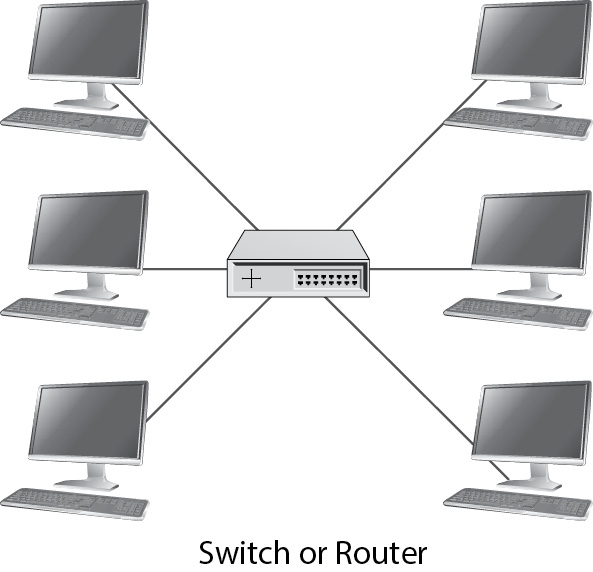
Figure 6-1 A star network topology
Bus Topology
In a bus network, all nodes are connected to via a single cable, looping from node to node, as illustrated in Figure 6-2. This type of network may be used for different types of control systems, such as lighting controls. As with other network topologies, each node is identified by a unique number. This number is set either in software or by a mechanical switch.
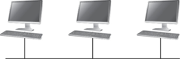
Figure 6-2 A bus network topology
Ring Topology
Similar to a bus network, a ring network connects nodes one after another in sequence. The biggest difference between these technologies is that with a ring topology, the ends of the network are then connected to form a continuous loop, as illustrated in Figure 6-3. Information can flow around the loop or ring, and if there is a break in the line, the information will still flow because redundant paths can be created.

Figure 6-3 A ring network topology
Telecommunication utilities and WAN Internet services often use a mesh ring topology to create redundancy.
Mesh Topology
In a mesh network, each node is connected via bridges, switches, or routers to at least one other node, as illustrated in Figure 6-4. This configuration allows the nodes to distribute data via many possible paths, providing high resilience to failure. Mesh topology is used for ad hoc wireless networks where wireless nodes may connect or disconnect at unpredictable intervals and where one node may act as a relay for other distant nodes.

Figure 6-4 A mesh network topology
Mesh topology is frequently used in building automation networks and the device and instrumentation networks collectively known as the Internet of Things (IoT).
As you can see, communication between devices can be complicated. Making these networks work as intended would be especially difficult if standards were not developed. One of these standards is Ethernet, as discussed next.
Ethernet
Ethernet is the most commonly used method of transferring data on a LAN. It is an Institute of Electrical and Electronics Engineers (IEEE) standard that governs how computers exchange information over the network medium.
The Ethernet standard specifies the physical transmission media (cable, fiber, wireless) and how signal information is handled (frames or packets) on a network. The standard is called IEEE 802, and it is revised periodically to include improved technology and applications. Such revisions are indicated as 802.x.x, where the xs represent the revision numbers.
Variations of Ethernet operate in all LAN topologies and use a variety of network media (cable, fiber, and wireless). The topology and the connecting medium determine the speed and distance of data transfer.
Ethernet is a packet-based system. Large files or streams of data are broken into smaller chunks called packets. These packets are 1,500 bits or smaller. Because of the nature of Ethernet, it is possible for packets to take different paths and arrive at the destination at different times or out of order. The receiving device must keep track of missing packets and either request the missing information again or have the ability to ignore missing packets. Ethernet is designed as a “best-effort” delivery system.
Ethernet Connections
As with other communication devices, Ethernet cabling must be connected to the device by attaching some type of connector. A common Ethernet connection is made with an eight-position, eight-conductor (8P8C) modular connector, as shown in Figure 6-5, which is attached, or terminated, to the cabling. An 8P8C connector is commonly referred to as an RJ-45 connector. The 8P8C is relatively inexpensive and easy to install in the field.

Figure 6-5 An 8P8C modular jack (RJ-45) termination
There are two wiring formats within the IEEE 802 standard: T568-A and T568-B; the overwhelming majority of installations and premade cables use the T568-B format.
If a cable is terminated with a T568-A on one end and T568-B on the other, the cable is known as a crossover cable. A crossover cable allows two devices, such as two computers, to connect and share information without the use of a switch or router (which normally does the crossover electronically).
Fiber-Optic Connections
Fiber-optic cabling is commonly used for Ethernet where long cable runs and high data speeds are required. Fiber-optic cables work by sending information coded in a beam of light through a glass or plastic pipe.
A fiber-optic cable consists of a strand of optical fiber as thin as human hair. Fiber can easily accommodate LAN speeds of 40 gigabits per second (Gbps) and can be used at higher speeds by upgrading the transmitter and receiver technology. Fiber has been tested up to hundreds of terabits per second (1Tbps = 1,000Gbps), which makes it a good choice for long-term investments in upgradeable cable plant.
There are two types of fiber-optic cable:
• Single-mode Single-mode means that the transmitted light travels on a single light path. You can typically identify single-mode fiber-optic cable by its yellow outer protective jacket.
• Multimode Multimode means it travels on multiple light paths. Multimode fiber-optic cable is identified by an orange jacket.
The signals that travel along single-mode fiber can reach farther distances than signals on multimode because of the construction of the cable.
Several types of terminations are used for fiber-optic cable. The most commonly used are ST, LC, and SC, as illustrated in Figure 6-6. The ST connector uses an insert-and-twist connection, much like a BNC connector. The LC connector is known as a “push, pull” connector. The SC connector inserts and clicks into place.

Figure 6-6 Common fiber-optic connectors
Wireless Connections
In addition to transmitting signals over a cabled networked system, you can transmit signals wirelessly, with special devices on each end of the wireless signal to translate it back into wired Ethernet. The wireless connection, known as Wi-Fi, is defined by the IEEE 802.11 standard and is continually being revised to keep up with the growing demand for wireless communication. Currently, IEEE developers are working on 802.11 standards that would provide even greater speed (throughput)—theoretically, up to 20 Gbps.
The network device that handles the wireless connection is called an access point. For two devices to establish a wireless connection, the radio frequency (RF) signals for transmission must have a minimum level of signal strength. To maintain proper signal strength, the devices should be as close together as reasonably possible. Even though some wireless systems claim a distance limitation of 70 meters (about 230 feet), the real distance limitations have more to do with the transmitting antenna, the receiving antenna, the obstructions between the two, and the power output of the transmitters on both ends.
In summary, the speed of a Wi-Fi connection depends on the RF signal strength and the revision of 802.11 with which you connect. As signal strength weakens, the speed of the connection slows. Another factor affecting connection speed is the number of users accessing the wireless devices.
Table 6-1 lists the specifications of the revisions of the 802.11 standard for wireless networks.
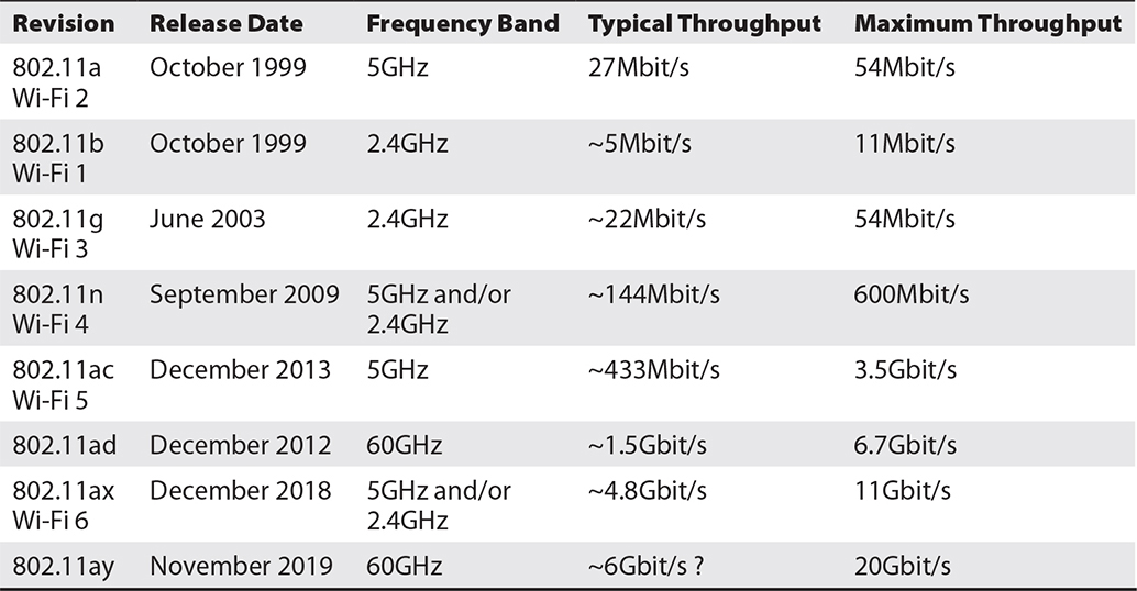
Table 6-1 802.11 Standard Revisions
The OSI Reference Model
No matter what kind of connection you are using for your network, the framework that enables communication between devices must be standard, and you must have a common language to describe the process. The Open Systems Interconnection model was developed by the International Organization for Standardization (ISO—yes, they know the initials don’t match) to standardize communication between devices all over the world, including those on the Internet.
The OSI model separates communication connectivity into seven different layers, each with a specific duty, as shown in Table 6-2. This allows for a variety of connection types, as well as the development of specific hardware and software to optimize the network. The layers are processed in a specific, sequential manner.
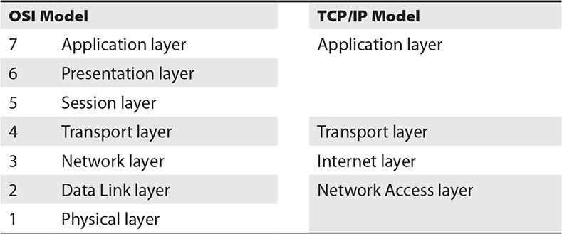
Table 6-2 The seven layers of the OSI model compared to the TCP/IP model
As data is sent out, each layer adds some information to keep track of the file or data stream as it passes through a network. This system allows packets to be tracked and recombined at the receiving end to recover the file or stream.
When an application sends data, the data moves down the layers until it finally reaches the network medium at the Physical layer (layer 1). As the data is processed by protocols at each layer, it is divided into smaller units that may be easily transported and reassembled at the other end.
Information starts at the uppermost layers (layers 7, 6, and 5) and continues to the lower layers. The large files, or streams, in the upper layers are broken down into smaller chunks of information, called segments, in the Transport layer (layer 4). At the Network layer (layer 3), destination and control information is added to the segment, forming a packet. These packets are sent across the network. The destination and control information provides for error checking. At the Data Link layer (layer 2), packets are encapsulated into frames that contain information about the physical destination, such as the MAC address. The final data frame (in this case for Ethernet) is put on the network medium by the Physical layer (layer 1).
The following is a brief summary of what happens in each layer, plus how each layer relates to AV/IT systems. AV professionals will want to pay particular attention to layers 7 and 1.
Layer 1, the Physical layer, covers cabling and other connection mediums, such as patchbays and more. The Physical layer does the following:
• Defines the relationship between the device and a physical means of sending data over network devices (such as a cable)
• Defines optical, electrical, and mechanical characteristics
Layer 2, the Data Link layer, includes the Ethernet standard and unique hardware addresses. Switches and Bridges operate at this layer. The Data Link layer does the following:
• Defines procedures for operating the communication links
• Encapsulates data into Ethernet frames
• Detects and corrects packet-transmission errors
Layer 3, the Network layer, is where the Internet Protocol (IP) comes into play. Routers and layer 3 switches operate at this level. The Network layer does the following:
• Determines how data is transferred between network devices
• Routes packets according to unique network device addresses
• May provide flow and congestion control to prevent network resource depletion
Layer 4, the Transport layer, governs the transfer of data. Gateways operate at this level. The Transport layer does the following:
• Provides reliable and sequential packet delivery through error-recovery and flow-control mechanisms
• Provides connection-oriented or connectionless packet delivery
• Provides flow and congestion control to prevent network resource depletion
Layer 5, the Session layer, is the first of the upper layers and concerns the data itself, ensuring data passes properly through the network. The Session layer does the following:
• Manages user sessions and dialogues
• Controls the establishment and termination of connections between users
• Reports upper-layer errors
Layer 6, the Presentation layer, unpackages data for use by the Application layer. It also does the following:
• Masks data format differences between dissimilar systems so they can communicate
• Specifies an architecture-independent data-transfer format
• Encodes and decodes data, encrypts and decrypts data, and compresses and decompresses data
Layer 7, the Application layer, presents data to the application software for use. The Application layer also does the following:
• Defines an interface to user processes for communication and data transfer in a network
• Provides standardized services, such as file and job transfer, and operations
The TCP/IP Networking Model
The Internet Engineering Task Force is the body that specifies all the standards used for the TCP/IP system used in the Internet. These standards include Simple Mail Transfer Protocol (SMTP) used for e-mail; File Transfer Protocol (FTP) used for file transfer; the Domain Name System used for naming Internet domains such as AVIXA.org; Hypertext Transfer Protocol (HTTP), which is the basis for the World Wide Web; and even the IP address numbering systems. As shown in Table 6-2, the communications model used in the TCP/IP system nominates only four layers:
• Application The Application layer includes the functions of the Application, Presentation, and Session layers (layers 5 through 7) of the OSI model.
• Transport The Transport layer matches the Transport layer of the OSI model.
• Internet The Internet layer matches the function of the Network layer of the OSI model.
• Network Access The Network Access layer includes the functions of the Data Link and Physical layers (layers 1 and 2) of the OSI model.
Network Interface Cards and MAC Addresses
To connect a device to a network, an interface of some kind is required. This interface is called a network interface card (NIC). At one time, most devices had a separate card or adapter. While separate cards are still common, in some cases they have been replaced by integrating the NIC into the device’s main circuitry. Even wireless connections are considered NICs because they interface between RF transmissions and traditional wired cabling.
A media access control address (MAC address) is the actual hardware address, or number, of a NIC device. Each device has a globally unique MAC address to identify its connection on a network. It is part of the IEEE 802 standard.
The MAC address uses a 48-bit (248) number that consists of six groups of two hexadecimal numbers, separated by a hyphen or colon. Here are two examples:
01-23-45-67-89-ab
01:23:45:67:89:ab
The numbers come from a table of numbers assigned to manufacturers of Ethernet-capable devices. The first part of the number indicates the manufacturer, and the second part is a serial number for the product or circuit component. Because of the nature of a MAC address, there can be only one device with that number on any given network.
The MAC address is one of the lowest levels of communication on the network. It is one of the first pieces of the network communication structure. Because each address is unique, switches and routers can store MAC address locations to efficiently send data traffic throughout the network to a specific device.
Internet Protocol Addressing
How do you get a network to acknowledge a networked device? Your device has a means of connecting (the NIC)—via cable, fiber, or wirelessly—and a unique number to identify it (MAC), so how do you connect it to the network? This is the role of the IP address. The IP address defines the exact device and its location on a network.
When describing a network, there are distinctions between names, addresses, and routes. A name indicates what you seek. An address indicates where it is. A route indicates how to get there. IP deals primarily with addresses. It is on layer 3 of the OSI model.
Two versions of IP are used today: IP version 4 (IPv4) and IP version 6 (IPv6). Since 1982, IPv4 has been the standard IP addressing scheme, and it may still be for some time. However, IPv6 offers improvements over IPv4, including increasing the total number of devices that can have unique IP addresses, better routing capabilities, and greater efficiency in transferring data. IPv6 does not specify interoperability features with IPv4 but essentially creates a parallel, independent network. Modern operating systems include support for IPv6, and certain markets, such as the U.S. government, have programs in place to encourage (or mandate) the switch from IPv4 to IPv6.
Regardless of the IP version you use, there are two types of IP addresses: static and dynamic. A dynamic IP address is a temporary address automatically assigned to a network device upon connection to the network. A static address is one that is assigned manually and stays with the device.
We’ll cover the addresses for IPv4 and IPv6, subnetting, and static and dynamic addresses in this section.
IPv4
Every networked device needs an IP address to transfer data over an IP-based network. The IPv4 format requires a number made up of four 8-bit “chunks,” called octets, such as the following:
192.168.1.25
This number is actually a 32-digit binary number that looks like this:
11000000.10101000.00000001.00011001
The IPv4 address (number) given to a network device has a structure that includes a network prefix and a network host number. The left part of the IP address is the network prefix, and the right part is the network host.
IPv6
IPv6 has a similar structure to IPv4. However, instead of using a binary numbering system consisting of four groups of octets, IPv6 uses eight groups of four hexadecimal numbers. This change in number structure raises the number of unique network addresses.
• IPv4 has 232, or 4,294,967,296, potential IP addresses.
• IPv6 has 2128, or 340,282,366,920,938,463,463,374,607,431,768,211,456, potential addresses.
As you can see, IPv6 allows for many, many more addresses, reducing the probability that we would run out of potential IP addresses.
In practice, an IPv6 address looks something like this:
FEDC:BA98:7654:3210:FEDC:BA98:7654:3210
This format employs hexadecimal numbering, with letters representing the digits 10 (A) through 15 (F). To help ensure that two devices won’t receive the same host or node address, IPv6 can use the MAC address as part of its numbering scheme. Because a MAC address uniquely identifies an Ethernet connection, using this number should also uniquely identify the IP address. This provides an easy way for systems to keep track of addresses, though the method isn’t recommended in all cases.
Subnet Masks
A subnet allows IP networks to be logically subdivided, increasing performance and enhancing network security. Subnetting is a common practice, but it can actually cause performance problems under heavy traffic loads unless IT applies subnet masks to the IP addresses on its network. In short, in addition to an IP address, a networked device also needs a subnet mask, or it will not be recognized properly on a network.
As you’ll recall, an IP address has two components: the network address and the host address. A subnet mask separates the IP address into the network and host addresses. It “masks” or hides the network part of the address and leaves only the host number to identify the device. A subnet mask accompanies an IP address, and the two values work together to identify a device on a network. A subnet mask, with its four-octet form, appears similar to an IP address when written out. The difference comes to light when you decode the octets into binary.
A subnet mask of 255.255.255.0 is common for so-called Class C IP addresses and indicates the subnet can include 254 devices. A subnet mask of 255.0.0.0 indicates a network that can handle more than 16 million devices.
Static IP Addressing
Some networked devices require an IP address that will not change so that users or other devices can easily and always find it on the network. Examples are a videoconferencing system and IP-controlled equipment. Such IP addresses are called static addresses. In some cases, you may have no choice but to assign a static IP address to a device.
Commonly, when configuring a networked device for operation, you will find a check box to “obtain IP address automatically” (or similar wording). When you check this box and the device connects to a network, the network sees the new device. If there is a Dynamic Host Configuration Protocol (DHCP) server on the network, it will automatically assign an address to the device. This is a dynamic IP address, and it can be different every time the device connects (as described in the next section).
If there is no DHCP server on the network, you will need to manually set a static address. Whatever the situation, to set a static address, you will need the following information:
• IP address (required)
• Subnet mask (required)
• Device name
• DNS server
• Gateway
Dynamic IP Addressing
When a device connects to the network and the device has the “obtain IP address automatically” option activated, the DHCP service or server will read the MAC address of the device and assign it an IP address. The pool of available IP addresses is based on the subnet size and the number of addresses that already have been allocated.
A DHCP server will allow a device to hold the IP address for only so long; the amount of time is called the lease time. After the lease time has expired, the lease will usually be renewed automatically if the device is still connected to the network; otherwise, another device connecting to the network can reuse that same address.
The advantage of using DHCP is that it is rather easy to manage. It takes care of making sure no two devices get the same address, relieving potential conflicts. It allows for more people to connect to the network, as the pool of addresses is continually updated and allocated.
The disadvantage of using DHCP is that you never know what your IP address will be from connection to connection. If you need to reach a certain device by IP address, you must have a high level of confidence that the number will be there all the time, and DHCP will not give you that confidence.
A hybrid approach to DHCP is to reserve a block of addresses for static addresses and dynamic addresses. The pool of addresses for DHCP is reduced by the number of addresses reserved for static devices. To make this happen, an IT manager will need the MAC address of each device that must be statically set. The static (manually assigned) IP address and MAC address are entered into a table. When the device connects to the network and reveals its MAC address, the DHCP server will see that the IP address is reserved for the device and will enable it. The IP address cannot be given to any other device or MAC address.
The Domain Name System
The Domain Name System is a hierarchical, distributed database that maps names to data such as IP addresses. A DNS server keeps track of all the devices on the network and matches the equipment names so they can be located on the network easily or integrated into control and monitoring systems.
When a new device is connected to the network, the DNS server matches the name of the device to its IP address. Now a user can call devices by name instead of number. This is useful, especially on the Internet. For example, it’s easier to remember that the domain name of the Internet Engineering Task Force (IETF) is ietf.org than it is to remember the IP address 4.31.198.44.
When DHCP and DNS servers are working together, you may never need to know the IP address of a device; you need only its name. This makes managing a network simpler, as the IP address does not need to be static, and the entire addressing scheme could change without affecting the communication between devices.
Network Switches and Routers
When working with networked systems, you should also know about the hardware building blocks of the network itself. For example, a network switch connects multiple devices together so they can communicate with other devices that are also connected to the switch. Some routers have switches built into them, but a router does much more than a switch.
Network Switches
As each device is connected to a network, a switch collects its MAC address and stores it in memory. When one device wants to communicate with a second device, the switch looks up the destination device’s location in its memory. If the address is in the switch’s memory, the switch will send the information to its destination.
Switches also have the ability to allow connected devices to operate at their maximum speeds. If a 100Mbps device and a 1Gbps device are connected to a 1Gbps switch, both devices can use their maximum speeds. In other words, the 1Gbps device will not need to slow down to accommodate the slower device.
There are two basic types of switches:
• Unmanaged An unmanaged switch is one you simply plug in and connect devices—that’s it. There are no adjustments. It just works.
• Managed Managed switches give the IT manager the ability to adjust port speeds, set up VLANs, set up quality of service (QoS) settings, monitor traffic, and more. Managed switches are what you will find in most complex or multifunction networks.
Routers
A router works at the OSI layers above a switch’s layer, which are the Network and Transport layers. A router reads the destination IP address of the packets being sent, so it can be used to send the packets to specific locations or via predefined paths on the network. The IT manager can use a router to change how a network works. Routers also allow for redundancy in a network.
Routers work together in a hierarchy, as one router can control the behavior of routers beneath it.
Gateways
A gateway is usually the topmost router in the hierarchy of routers. This top-level router connects to an outside network. All traffic must eventually travel through this router to get outside the local network.
A gateway has special duties. It passes traffic to the routers below, which look to the gateway to find names (DNS addresses) that are not found on the local network. Sometimes a network device won’t operate if it doesn’t have a gateway address.
Bridges
A bridge connects two different types of networks. It translates one network protocol to another protocol. One basic example of a bridge is a broadband modem. The modem converts, or bridges, the Ethernet protocol to a WAN protocol.
Network Security
In a digital world, it’s hard to go a day without hearing or reading about network security issues. Often, it has to do with a network security breach, such as a hacker stealing financial information from a bank’s computers or some shadowy organization attacking a government website so that it can’t function. To the extent your AV systems must run on IT networks, you, as an AV professional, must have a working knowledge of network security.
The purpose of network security is to prevent unauthorized users from accessing a LAN. It is implemented at many points in the network, but most defenses operate at the boundaries of a system. The first of these boundaries is the physical network interface. Think of the wall port as an extension of the network switch to the wall. One method of control is to limit the MAC addresses that may use a port. The port can be configured so only certain devices can access the network from that point.
AV professionals must understand the network architecture so they can identify the boundaries and possible points of attack. That said, AV professionals who are designing or installing networked AV systems will usually not be responsible for actual network security. To make the AV system functional, they will need to coordinate with a client’s IT department or network security personnel so that the appropriate AV traffic can traverse firewalls and other security measures.
AVIXA standards have created a guidance document named Recommended Practices for Security in Networked AV Systems.
Network Access Control
Network access control (NAC) describes a group of technologies that secure a network. They are chosen to align with the security policy of an organization. In a nutshell, when an organization employs a NAC solution, any device that attempts to connect to that network must comply with the organization’s security policy, which may dictate everything from how the device is configured to the software it runs. And once a device connects to a network, NAC can control what that device can access on the network, based on user actions and identities.
Your AV system may need to interface with the client’s NAC technologies to work properly. Some AV devices have trouble with NAC because they are not fully functional computers.
Access Control Lists
When a network is broken into subnets or broadcast domains, routers may provide additional security. Routers may contain an access control list (ACL). An ACL controls what travels through a router based on the type of data traffic, source, and/or destination. If your AV system will require special access rights, be sure that IT creates an ACL for the system and adds the appropriate end users.
802.1x
One component of NAC may be the use of 802.1x, or port-based NAC. 802.1x is an IEEE standard that requires authentication before a device may connect to the network through a certain port. Prior to accessing the organization’s network, the user must be verified by an authentication server. The process is analogous to an airport security agent verifying your ID and ticket before allowing you to enter the terminal.
Firewalls
Firewalls are among the most common network security technologies. They can be software programs (chances are your personal computer runs a software firewall) or dedicated hardware devices. Their primary job is to control incoming and outgoing network traffic by analyzing packets and determining whether they should be allowed through, based on a set of rules.
Most firewalls accomplish their goal through one or more of the following techniques:
• Packet filtering This is a firewall technique that uses rules to determine whether a data packet will be allowed to pass through a firewall. Rules are configured by the network administrator and implemented based on the protocol header of each packet.
• Network address translation (NAT) NAT is a method of altering IP address information in IP packet headers as the packet traverses a routing device. NAT is used to allow devices with private, unregistered IP addresses to access the Internet through a device with a single registered IP address. NAT conserves address space, which is a concern in IPv4 implementations (though it’s also used for IPv6 networks). NAT hides the original source of the data. From outside the network, all data appears to originate from a NAT server. Any data that arrives at the NAT server without being requested by a client has nowhere to go; it has the address of the building but not the apartment number. Using NAT, all unrequested data is blocked by the firewall, and a malicious intruder can’t trace the data’s path beyond the edge of the network.
• Port forwarding This method combines NAT and packet filtering. The firewall inspects the packet based on packet-filtering rules. It is also configured to translate certain external ports to private addresses inside the network.
Navigating Firewalls
One of the most important factors in whether AV system traffic reaches its intended destination is the configuration of network firewalls. The firewall is the ultimate arbiter of what kinds of traffic can access a network through what ports. Because the firewall must protect the entire network, firewall configuration is a crucial area of coordination between AV design and overall network management.
An AV designer must list the ports and protocols that need to pass through a firewall as specifically and narrowly as possible so that the network managers can support the system without endangering the enterprise network. If you are anticipating a specific data stream for an AV application, you need to ensure its port will be open.
You should be able to determine which ports and protocols are required for a given AV application from the manufacturers of the devices used. The manufacturer specifications of any networked device should list the protocols and port ranges the device will use.
Chapter Review
Today, more than ever before, it is important for CTS-certified AV professionals to have an in-depth knowledge of IT networking. The most current CTS exam incorporates new network-related questions because AV systems increasingly interface with or communicate directly over the same types of networks that organizations use to connect their computers. It is also important for AV professionals to understand the basics of network technology to collaborate with IT departments on the design and installation of networked AV systems.
Review Questions
The following review questions are not CTS exam questions, nor are they CTS practice exam questions. Material covered in Part II provides foundational knowledge of the technology behind AV systems, but it does not map directly to the duties/tasks covered on the CTS exam. These questions may resemble questions that could appear on the CTS exam but may also cover material the exam does not. They are included here to help reinforce what you’ve learned in this chapter. See Appendix D for more information on how to access the online sample test questions.
1. Which of the following network topologies connects devices in sequence along a linear path?
A. Bus
B. Star
C. Mesh
D. Ring
2. Which IEEE standard defines Wi-Fi communications methods?
A. 802.1x
B. EIA-485
C. IPv6
D. 802.11
3. What happens to the connection speed in a Wi-Fi connection if the signal strength declines?
A. Speeds up
B. Stops
C. Slows down
D. Remains constant
4. Which of the following is a type of fiber-optic cable identified by its yellow outer jacket?
A. ST
B. SC
C. Multimode
D. Single-mode
5. The _____ model is a guide that assists with conforming network communications and their processes to standards.
A. Network interface
B. OSI reference
C. Informal data link
D. Asynchronous transfer mode
6. In the OSI model, cabling and patchbays are elements of _____.
A. Layer 2, the Data Link layer
B. Layer 4, the Transport layer
C. Layer 1, the Physical layer
D. Layer 3, the Network layer
7. A _____ address is unique to every device and identifies a network’s equipment.
A. Transfer mode
B. Baseband
C. Digital subscriber line
D. MAC
8. IP deals with which of the following on a network?
A. Addresses
B. Names
C. Routes
D. Versions
9. An IPv6 address uses _____ groups of four hexadecimal numbers.
A. Three
B. Eight
C. Six
D. One
10. Subnet masks can indicate how many _____ are allowed on the network.
A. Computers
B. Gateways
C. Devices
D. Printers
11. What is required to set an IP address manually on a network?
A. IP address and device name
B. Subnet mask and gateway
C. Subnet mask and DNS server
D. IP address and subnet mask
12. Which type of server automatically assigns an IP address to the MAC address during the device’s connection to a network?
A. Gateway
B. Virtual private network
C. DNS
D. DHCP
13. Which of the following switches just needs to be plugged in and connected to devices?
A. Unmanaged
B. LAN
C. Addressing
D. Managed
14. A _____ sends packets to different locations on a network and connects to outside networks.
A. Switch
B. Gateway
C. Bridge
D. Router
15. A _____ controls incoming and outgoing network traffic and determines what will be allowed through based on a set of security rules.
A. Switch
B. Gateway
C. Firewall
D. Router
Answers
1. A. A bus network connects devices in sequence along a linear path.
2. D. The IEEE 802.11 standard defines Wi-Fi communications methods.
3. C. The connection speed in a Wi-Fi connection slows down if the signal strength declines.
4. D. Single-mode fiber-optic cable can be identified by its yellow outer jacket.
5. B. The OSI reference model is a guide that assists with conforming network communications and their processes to standards.
6. C. In the OSI model, cabling and patchbays are elements of layer 1, the Physical layer.
7. D. A MAC address is unique to every device and identifies a network’s equipment.
8. A. IP deals with addresses on a network.
9. B. An IPv6 address uses eight groups of four hexadecimal numbers.
10. C. Subnet masks can indicate how many devices are allowed on the network.
11. D. An IP address and subnet mask are required to set an IP address manually on a network.
12. D. A DHCP server automatically assigns an IP address to the MAC address during the device’s connection to a network.
13. A. Unmanaged switches just need to be plugged in and connected to devices.
14. B. A gateway sends packets to different locations on a network and connects to outside networks.
15. C. A firewall controls incoming and outgoing network traffic and determines what will be allowed through.