
CHAPTER 17
Integrating AV Solutions
In this chapter, you will learn about
• Installing AV equipment and systems
• Setting up and configuring AV equipment
• Configuring systems for network connectivity
• Producing live AV events
• Providing support, documentation, and training for end users
A key part of the AV professional’s skill set is the ability to build and install AV equipment and systems at a client site. This requires the AV professional to be able to read and understand AV system design documentation, know how to physically install AV components, and know how to configure the components within the overall AV system. This expertise is typically built up over a period of time, both from work experience and from study.
This chapter reviews some of the basic tasks and procedures that you will perform when building an AV solution for a client.
The knowledge and skills required to provide AV solutions include the following:
• Installing AV equipment and systems in a technically correct and professional manner requires an understanding of the AV design specifications created for the client system.
• Installing AV cabling and racks requires basic skills in construction, such as mounting, pulling cables, and working safely at construction sites.
• Setting up AV systems requires knowledge of how to properly configure AV components and interconnect them via a control system or over a computer network. This can include designing a control interface and/or configuring AV systems to operate within the security, bandwidth, and other requirements of an IT network, if applicable.
• Producing live AV events requires knowledge of equipment setup and configuration to support a presentation or performance.
Domain Check
Questions addressing the knowledge and skills related to building and providing an AV solution account for about 10 percent of your final score on the Certified Technology Specialist (CTS) exam (about 10 questions).
Installing AV Equipment and Systems
In this section, we will review some of the issues, tasks, and procedures associated with installing typical AV components and systems at client sites. We’ll cover the following topics:
• How to prepare for the installation
• Safety concerns when working at a job site
• Cable termination
• Rack construction
• Cable handling and pulling
• Mounting AV components
Preparing for the Installation
Preparation is central to a successful and efficient system installation, both permanent and temporary. CTS-certified professionals are responsible for understanding how their work impacts the company’s overall strategy.
Before installing an AV system, you should prepare as follows:
• Know the priority of each project.
• Review the project documentation with the sales representative, designer, and/or project manager.
• Understand the scope of your responsibilities and how successful completion of your work is measured.
• Know which job site(s) you are going to work at each day.
• Determine a plan for when you get to the job site.
• Examine the relevant facility and system drawings and specifications prior to beginning work.
• Verify you have the necessary tools, equipment, consumables, and manuals for the installation tasks.
• Open and inspect each piece of equipment upon arriving at the job site. Check for any damage, and power on and run basic tests on each device to verify that it is in good physical condition.

TIP Each installation, whether permanent or temporary, will require different equipment. Make a checklist of the equipment needed for each type of job and keep it in the job file. When picking up the equipment and assembling it for installation, a quick glance at the checklist will confirm that everything is ready to go. If the installation is temporary, use the checklist when you disassemble it to account for all the equipment.
Job Site Safety Concerns
Safety should always be your primary concern when working at a job site. Job sites may present numerous hazards and safety issues, ranging from falling and electric shock hazards to exposure to sharp surfaces and head injury.
In Chapter 12, we covered how AV professionals working at a job site must comply with all applicable safety regulations, as well as local, regional, and national safety codes. Depending on conditions at the work site, anyone working there may be required to use personal protective equipment (PPE), such as hard hats, protected-toe footwear, work gloves, hearing protection, and safety glasses. Workers should also use the appropriate tools and equipment necessary for safely performing the work, such as approved ladders and fall protection when necessary.
Cable Termination
Cable termination is a significant part of what AV professionals do when installing AV systems. It refers to the method of establishing connections at each end of a cable. In this context, cable refers to any number of insulated wires—with or without a shield—protected in a jacket. Cable termination requires selecting the appropriate cable and connector for a specific need and using the proper method and tools to install the connector on the cable.
Poor cable terminations, which cause disruption in the flow of electricity or signal, are the single most prevalent problem in electronic systems. Poor terminations are expensive to track down and fix after the system is built. Termination-related problems are particularly hard to troubleshoot because the problem can be intermittent and difficult to locate. You can easily avoid these problems by using the appropriate tools and connectors, as well as taking the time to properly perform the termination. A CTS-certified professional must be an expert in terminating cable.

NOTE Poor cable terminations are the number-one cause of problems in AV systems, yet they can be difficult to track down.
Termination Preparation
Cable stripping is the process of preparing the cable for the connector by removing the jacket from the end of a cable (and sometimes the shield and/or insulation from individual wires) to reveal the conductor. Precise stripping assures a good physical match with the connector. Stripping cable improperly can distort the shape of the insulation, thereby altering the impedance properties of a cable.
The technician should use a stripping tool designed for the specific type of cable and connector. The stripper depicted in Figure 17-1 is used for stripping solid or stranded cables. Special multibladed strippers are used for coaxial cable.
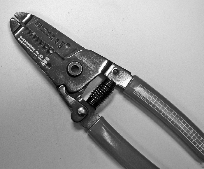
Figure 17-1 A cable stripper tool
The outer jacket of the cable is the first thing to be removed. When doing so, you need to be careful not to disturb the wire(s) underneath the cable jacket. For some termination types, such as insulation displacement, you remove only the jacket. For most connectors, you will need to continue by removing the individual insulation from each conductor and cutting each conductor to the correct relative length.
Termination Methods and Types of Cables and Connectors
The type of termination depends on the cable and what you will connect it to. Termination methods include the following:
• Direct-connection termination Also known as screw-down termination, this is a method in which the wire is directly connected to a piece of equipment, as depicted in Figure 17-2 and Figure 17-3. This connection type is used for permanent connections. The most basic direct-connection terminations are the barrier strip, utility block, and screw terminals. These connectors are often used for loudspeakers, remote-control relay switches, and points of demarcation. In such cases, a solid conductor is wrapped around the screw, or a spade is crimped to a stranded conductor, and the screw is tightened to secure the wire or lug to the connection.

Figure 17-2 Direct connections using solid conductors
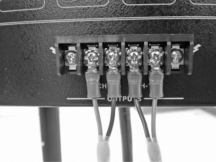
Figure 17-3 Direct connections using stranded conductors
• Compression termination In the compression termination method, a screw applies pressure to a flat plate to squeeze the wire and hold it in place. It uses a captive screw connector, as depicted in Figure 17-4.

Figure 17-4 A captive screw compression connection
• Soldering termination This is a method of joining metal by employing heat and a metallic alloy. Here are some connectors that usually require soldering:
• The XLR connector, shown in Figure 17-5, is used as a standard low-impedance connection for balanced audio circuits and other applications. These connectors can have three to seven pins.

Figure 17-5 An XLR connection
• The phono or RCA connector, shown in Figure 17-6, is used for interconnecting legacy composite video, unbalanced audio, and a variety of other applications.

Figure 17-6 A phono or RCA style connection
• The phone or 6.5mm (1/4-inch) connector, shown in Figure 17-7, is available in either a tip, sleeve (TS) or tip, ring, sleeve (TRS) configuration. It is used primarily for line-level audio signals.

Figure 17-7 A phone or 6.5mm (1/4-inch) connection
• The 3.5mm (1/8-inch) jack connector in the TRS configuration, as shown in Figure 17-8 is used primarily for line-level stereo audio from computers and multimedia devices.

Figure 17-8 A 3.5mm (1/8-inch) jack
Different connectors may require slightly different soldering techniques to create a proper termination. Figure 17-9 depicts the process of soldering a wire to part of a phone connector, using a pencil-type soldering iron and solder.
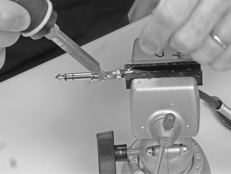
Figure 17-9 Soldering a wire to a phone or 6.5mm (1/4-inch) connector
• Crimping termination Applying pressure with a hand tool enables a connector to be properly attached to a cable. Crimping is a permanent action.
• Linear-compression termination The cable is inserted into a special linear-compression connector and hand tool. A BNC connector, such as the one in Figure 17-10, may be used for interconnecting video and RF equipment. You can secure the AV signal cable in a BNC connection using linear compression, as depicted in Figure 17-11. Linear compression is a permanent action.

Figure 17-10 A BNC connector
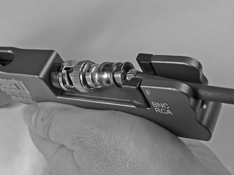
Figure 17-11 A BNC connector terminated to coaxial cable by linear compression
• Insulation-displacement termination This type of termination requires a special hand tool with a slot for an insulated wire. As the wire is pushed through the slot, the insulation is cut, and a metal strip makes contact with the conductors. The pressure displaces the insulation and tightly grabs the conductor. You can use this method with solid or stranded conductors, employing any of a number of hand tools, each specific to its application. The ubiquitous, eight-pin, eight-conductor modular connector, the 8P8C or RJ-45 (shown in Figure 17-12), is terminated using insulation displacement. Such connections are created using a compression tool that displaces the cable insulation to create the termination, as depicted in Figure 17-13.

Figure 17-12 An 8P8C or RJ-45 connector terminated by insulation displacement
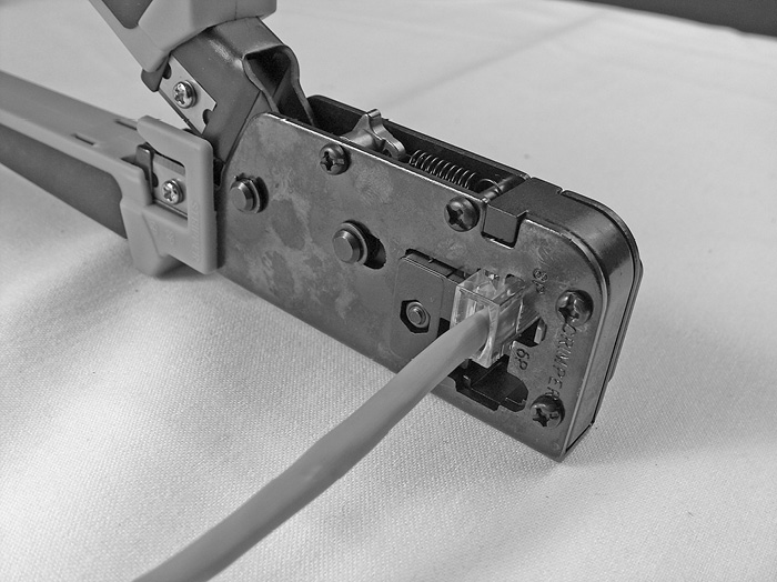
Figure 17-13 An 8P8C and 6P6C insulation displacement tool
Evaluating and Testing Terminations
For quality control, you must evaluate and test all terminations. It is more cost-effective to test the quality of a termination immediately after it has been completed than after the entire system has been built.
You should visually inspect terminations for the following:
• Stray wires that may produce short circuits
• Use of the correct wires at the appropriate contact points or pins
• Excessive or insufficient solder
• Sharp protrusions, extensions, or evidence of foreign matter
CTS-certified professionals should use the appropriate tool to test terminations for continuity or shorts. A multimeter is a common testing tool for many types of terminations (shown in Figure 17-14). The 8P8C modular connector has a specific device to test pin-to-pin continuity (shown in Figure 17-15).

Figure 17-14 A multimeter
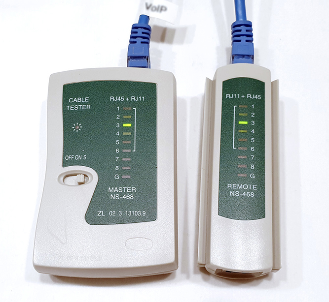
Figure 17-15 A low-cost 8P8C continuity tester
Proper termination, regardless of the type or method, requires the AV professional to understand and adhere to specific procedures, use the correct connectors and tools for the wire and connection type, and follow appropriate safety procedures. Termination is a key element of the AV technician’s skill set and requires practice to master.
Rack Building
All the cables in an AV system eventually lead to electronic equipment. The equipment is often located in a rack. An equipment rack is the skeletal framework where system components are housed, arranged, and interconnected. As with cable termination, AV installation technicians spend a great deal of time building racks, dressing cable, and troubleshooting.
Rack layout and installation is a process of evaluating options that meet the client’s needs. You should not mount equipment haphazardly in a rack. Here are some considerations for rack layout:
• How much heat a piece of equipment emits
• How the heat will be managed in the rack
• The types of signals present on interconnecting cables
• Whether the equipment installed in the rack has interface components that a user must be able to access
• The weight distribution of components in the rack
The AV system designer usually lays out a rack configuration for the AV technician to assemble, including the number of rack units (RUs) necessary for each piece of gear. However, it is important for the AV technician to understand the basic design concepts and techniques associated with rack assembly.
Rack building consists of three distinct tasks:
• Building the rack itself Assembling the frame, shelves, panels, cable management hardware, power distribution, and so on
• Installing the equipment Loading and securing the equipment in the correct place.
• Wiring the hardware together Creating the interconnections that enable the system to function
AV designers typically define how installers should arrange equipment in a rack using system design documents, such as elevation drawings or layouts and system wiring diagrams. A rack-elevation diagram is a graphical representation of the rack and the location of each piece of equipment in the rack. Figure 17-16 shows an example of a rack-elevation drawing.

Figure 17-16 A rack-elevation drawing
Ergonomics
AV equipment should be positioned in a rack based on a typical user’s need to access the equipment. Equipment with user-interface components (such as patch fields, graphic equalizers, and optical media players) should be placed within easy reach. Devices that do not require frequent access can be placed at the top or bottom of the rack.
You may also be required to locate equipment in a rack so that people who are disabled can access its interface. Any feature of the equipment that normally requires user interaction (such as a control interface or a place to insert removable media) should be between 380 and 1,220mm (15 inches and 48 inches) above the floor. This limits the space available for accessible equipment, depending on the system design, to about 840mm (33 inches) per rack. In some cases, additional racks may be required.
Weight Distribution
You should place equipment in a rack in a way that takes into consideration the weight of the equipment. Basically, you want to avoid a top-heavy configuration, which may result in an unstable rack. Unless the equipment rack is fastened in place, the best place for heavy components is at the bottom of the rack. If you place them near the top of a free-standing rack, the rack could tip over.
Most equipment is supported entirely by the rack screws in the front-mounting rail. Heavier equipment typically occupies two or more RUs, providing more support. However, some equipment may need the additional support of rear mounting rails. This is especially true with heavy pieces that occupy only one or two rack spaces, because the weight of the equipment can cause considerable torque on the front panel.
RF and IR Reception
Many racks contain transmitters and receivers for communicating with remote devices using RF or IR signals. For example, it is common for an AV system design to include a rack-mounted RF wireless microphone receiver. The antennas for the receiver must be located so they can receive the RF signals from the transmitter. If an antenna is located in the back of a metal rack, the rack itself acts as a shield, greatly reducing the RF energy before it can reach the antenna. Some manufacturers design rack-mounted receivers with antennas that face forward. Alternatively, you may be able to locate the antennas away from the rack, closer to where the transmitters will be used.
IR receivers must be within the line of sight of transmitters or else be equipped with a dedicated relay emitter system.
If a rack has a metal door and wireless receivers are rack-mounted, it will interfere with RF and IR signal reception. Generally speaking, a transparent acrylic door will not interfere with these signals.
Heat Loads
The amount of heat that electronic equipment generates is related to its power consumption. Racks contain heat-generating AV equipment mounted close together, so they require a method for removing hot air. The following are the three main ways of cooling a rack:
• Convection cooling This type of cooling relies on the fact that hot air rises to move heat upward and out of vents at the top of the rack. The vents must be large enough to accommodate the output, and there must be a means for cool air to get in at the bottom. Convection cooling is suitable only for racks that produce a relatively small amount of heat.
• Evacuation cooling This type of cooling uses fans to draw hot air out of the rack, usually through top vents. Cool air is passively drawn into the rack from the bottom vents to replace the hot air. Also, some electronic equipment has vents in the chassis so hot air can escape. It is important not to cover such vents or position the vents at the air intake of the units above it.
• Forced air cooling This type of cooling uses an approach that’s the opposite of evacuation. It uses fans to force cool or even chilled air into the rack from below, and uses vents at the top of the rack to provide an exhaust for the hot air.
You should also manage heat in a rack by separating equipment that produces a lot of heat and/or placing the equipment that produces the most heat near the top of the rack. Consider using vented panels placed at various positions in the rack to increase airflow. You may also use blank panels to separate components and allow for sufficient airflow inside the rack.
Signal Separation
As shown in Figure 17-17, signal separation is the process of grouping equipment and cables within a rack according to function and signal type to reduce crosstalk among cables resulting from electromagnetic interference (EMI). For example, a typical rack may include cables carrying low-voltage microphone-level signals (such as 0.001V) and cables carrying loudspeaker level signals (such as 30V). Maintaining physical separation between cables carrying different signal levels can help to maintain the integrity of the signals.

Figure 17-17 Signal separation in an equipment rack
Rack Assembly
Rack assembly is often best performed in the AV installer’s workshop, where the technician has access to components, supplies, tools, and other experienced personnel. The basic process of rack assembly includes the following steps:
• In some cases, the first step in building an equipment rack is actually assembling the rack itself. It may come in many pieces that must be put together prior to placing electronic equipment inside.
• Install all rack mechanical accessories. These can include power and grounding strips, horizontal and vertical cable management systems, casters, and fans.
• Assemble the equipment to be mounted in the rack.
• Document any information, such as equipment serial numbers, to include in manuals you will provide to the client. Some serial numbers or product labels can be difficult to locate after the equipment is in the rack. Therefore, it’s important to gather this information before loading the rack.
• Install mounting ears on equipment where necessary. Mounting ears are metal brackets you attach to an AV component so that you can mount it in a rack. They could be optional accessories purchased from the equipment manufacturer, or they could be included with the equipment. Some AV equipment has built-in mounting ears.
• Identify the intended locations for specific components and install them in the rack appropriately. Keep in mind that attempting to hold individual pieces of equipment in place while installing the mounting screws can be hard work. A common best practice is to lay the rack on its back on top of a protective sheet so that the rack is not scratched or damaged. You can then insert the equipment from above, as shown in Figure 17-18.
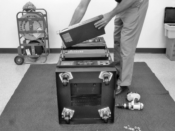
Figure 17-18 Installing components in a rack
TIP If you must insert equipment in an upright rack, have a colleague help, because it is difficult to hold equipment steady while securing the rack.
• Fill all rack spaces with equipment, blanks, vents, or power strips, so that the space matches your rack-elevation drawing. Empty spaces can affect air flow.
• Fasten the equipment mounting ears to the rack rail using screws.
• Make all internal rack-wiring connections between equipment inputs and outputs and organize the cabling. Use the AV system block diagrams to determine the signal path through a system. This step requires several additional tasks:
• Select the appropriate cables and connectors for the equipment and signal type.
• Carefully consider placing cabling runs so that they rest gently, without any tight bends, and are grouped in a manner that will maximize signal separation.
• Ensure proper cable lengths. You may want to provide extra cable length so that the user (or your company’s support staff) can move components for maintenance, but try to keep cable lengths close to the minimum necessary to reduce the potential for signal degradation.
• Terminate cables using the correct technique for the termination method.
• Label cables clearly.
• Tie off cabling using cable ties.
• Test cable continuity.
• Attach cables to the equipment.
• Install the AC power components defined in the rack design documents and applicable codes and standards. This step may include configuring the system to access more than one AC power circuit, properly placing transformers (to allow for service access and minimize electrical interference), and ensuring proper grounding both for safety and to minimize the potential for hum.
When it’s finished, a properly configured AV rack should appear neat and professional, both inside and out. All interior cabling should be routed in a neat and orderly fashion and properly secured to the rack’s cable management infrastructure.
Cable Handling and Pulling
In addition to racks, AV systems typically include components located throughout a room, or several rooms in a building, and most of them will be connected with cabling. CTS holders must be able to install cabling in a manner that meets applicable codes and regulations and ensures proper system operation. They should also ensure the cabling remains as unobtrusive as possible. AV installers must understand the requirements for properly handling and installing cabling according to the approved system design.
Technicians install cable along a path from source to destination, usually through cable raceways such as ducts; conduit, junction and pull boxes; cable trays; or ladders. Typically, electricians install the required cable support or enclosure hardware in a building, while AV technicians use that infrastructure to install cables.
As Figure 17-19 illustrates, conduit connects to junction and pull boxes at various locations. Junction boxes are installed at the ends of conduit runs. Pull boxes are installed at intermediate positions along the conduit run so that technicians have access to pull cable through the conduit. Pull boxes should be specified for every 30 meters (100 feet) of conduit, or after 180 degrees of bend in the conduit.
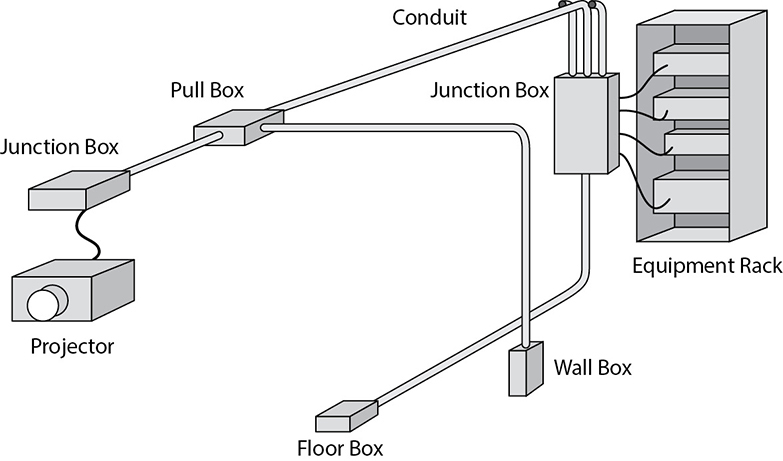
Figure 17-19 Schematic representation of a conduit system used for routing AV cables to various destinations within a room
At its ends, a cable is terminated to a panel in a wall, to a floor box, or directly to AV equipment. If the termination is at a wall or floor box, it may actually be to a socket for connecting another cable (such as for a microphone) or to a switch or control panel.
Raceways, Conduit and Other Cable Support Systems
A raceway is an enclosed channel designed expressly for holding wires and cables. Raceways include, metallic and non-metallic conduits and ducts. Other cable support systems include cable trays, cable ladders, wireways and troughs.
Conduit can refer to any pathway, but in the AV and electrical industries, conduit is a circular tube that houses cable. Polyvinyl chloride (PVC) conduit offers no protection against EMI, so it should not be used for unshielded AV cabling. When electrically-grounded, metal conduit, shown in Figure 17-20, offers a level of protection from either incoming or outgoing EMI. Conduit is a suitable enclosure when small numbers of cables are to be run to separate locations.

Figure 17-20 Various types of conduit
AV systems can use a range of metal conduit, including the following:
• Electrical metallic tubing (EMT) is probably the most popular type of conduit. In North America it is called thinwall because the metal is not very thick. You should not use EMT in an environment where the cabling will take a lot of mechanical abuse, such as a gymnasium or theater stage.
• Flexible metal conduit, often called flex for short, is typically connected to a movable piece of equipment. For example, flex may be used to house cable for a document camera on a cart or trolley that may be pulled away from a wall.
• Rigid-metal conduit (RMC), also called rigid, is the heaviest conduit and offers the best physical protection, making it the best choice for electronically noisy and/or harsh physical environments. It comes with prethreaded ends. Because RMC cannot be bent on-site, bends require the use of appropriately angled elbow couplers.
A conduit’s internal diameter determines how much cable will fit inside. The maximum amount of space (cross-sectional area) that cables can occupy in a conduit is called the permissible area. Permissible area is typically described in fill percentages (the share of conduit space the cables may take up) and will vary by jurisdiction. The following are examples of permissible areas within conduit for one to three cables (see Figure 17-21):
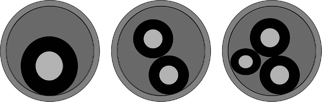
Figure 17-21 Examples of conduit capacity
• 1 cable = 53 percent If you are running only one cable through a conduit, that cable’s cross-sectional area may take up to 53 percent of the conduit’s internal cross-sectional area.
• 2 cables = 31 percent If you are going to run two cables inside a conduit, the sum of the two cables’ cross-sectional area may be up to 31 percent of the conduit’s internal cross-sectional area.
• 3 cables = 40 percent If you are going to run three cables through a conduit, the sum of the three cables’ cross-sectional area may be up to 40 percent of the conduit’s internal cross-sectional area.
When pulling cables through a conduit, the technician needs to determine the amount of space in the conduit that the cables will occupy. To do this, the technician determines the cross-sectional area that each individual cable will require and adds them together. The technician then compares the total area with the permissible area of the conduit to see whether the planned cable quantity will fit.
Ducts, troughs, cable trays, and cable ladders are suited to situations where many cables are being run to similar locations. Plastic wiring troughs may have snap-out slots to hold or help comb the cables. A cable tray is an assembly of units made of metal or other noncombustible material to provide rigid support for cables. Troughs, also called wireways and cable ducts, are sheet-metal wells with hinged or removable covers for housing cables. Metal troughs may be internally partitioned to provide separation between cable bundles and EMI separation between signal types.
Preparing Cables for Pulling
Cable pulling, like rack assembly, requires preparation. Because the installer needs to pull all the cables through conduit or troughs at the same time, it is an industry best practice for the installer to carefully plan which cables go into which conduit before pulling the cables. Some AV designs include a cable riser drawing, which depicts the interconnection of all the AV devices in a system. The CTS-certified professional should check the cable stock against the system drawings before proceeding, because making a mistake at this point can be very costly.
Upon arrival at the site to pull cabling, the installer should review the drawings and look around the room for boxes in the floor, ceiling, and walls. Boxes located in the ceiling are often hidden from view, so the installer may need to move ceiling tiles to find them. Wall boxes may be mounted at various heights, as appropriate for the devices that will be connected. Inputs for microphones and computers will probably be near the same height as general electrical and data outlets. Boxes for flat panel displays may be approximately 1800mm (70 inches) above the floor. Loudspeakers are typically mounted higher.
Installers should be aware that empty boxes can look similar. It can be easy to mistake the fire-alarm box for your loudspeaker location, or a networking box for a microphone connection point. So, be careful when identifying boxes. Also, follow health and safety regulations and site-specific safety requirements, including the use of PPE.
In most cases, installers must group together and pull multiple cables. A technician may combine and hold together multiple cables using a constricting metal grip, or create a bundle with electrical tape and a pull string, as shown in Figure 17-22. This is commonly known as a pull-through bundle (sometimes called a cable snout).

Figure 17-22 Creating a pull-through cable bundle
When combining multiple cables, ensure the appropriate level of signal separation by providing physical distance between cables that carry different signal levels. This helps to protect weaker signals from crosstalk. And because of signal-separation requirements, it’s important the installer, when grouping cables together in a bundle, ensures that all cables in that bundle are for only one signal type. Generally, group cables according to these categories:
• Microphone
• Line-level audio and communication
• Video
• Control and data
• RF
• Loudspeaker
• AC power
• Dimmed lighting
Above all, keep microphone cables separate from others. Microphone cables are the most susceptible to interference because microphone signal level is so low.
Labeling cables before installation is also important because it helps you track the cables and make sure each gets where it needs to go. A label, like the one shown in Figure 17-23, ensures each end of the cable is terminated with the correct connector and plugged into the correct input or output. Once the cables are pulled and terminated, you will apply permanent labels. Permanent labels make it easier to service the AV system.
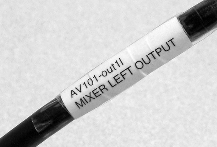
Figure 17-23 Cable label
Typically, the system engineer will pre-assign cable-identification nomenclature. This would be part of a cable run sheet. However, you may be called on to create the labeling scheme in the field.
With cable preparation complete, you can begin pulling cable.
Pulling the Cables
Once you have identified the conduit route, you need to employ some type of tool, such as a draw wire or fish tape, to pull the cable(s) from one end of the conduit to the other. When multiple turns are involved, you will usually pull cables in steps, using the pull boxes along the conduit path.
A draw wire or fish tape is a long, flexible, metal or fiberglass tape or cable, spooled like measuring tape, that AV technicians use to pull cable through conduit or narrow duct. They come in a variety of lengths and have a hook of some type on the end. First you feed, or fish, the tape or cable into the conduit from the far end until it reaches the end where the cable(s) will enter. Then you attach a pull string (or the cable itself, in simple situations) to the hook and pull the cable or cable bundle through the conduit. Roll up the tape or wire immediately when you’ve finished. If possible, roll the tape back onto the spool as you’re pulling it through the conduit because large amounts of loose fish tape or draw wire can be hard to handle.
When necessary, you can use lubricants to reduce friction when pulling cable. If you are using cable lubricant, apply it constantly to the cable as you pull.
Be aware that it is possible to apply harmful stress to cables when pulling. Pulling tension is the force used when handling cable. Applying too much force can stretch a conductor, changing its electrical properties, and this is critical when pulling twisted-pair cables. Larger cables can typically handle more force.
While good cable specifications may indicate acceptable pulling tension, the number is not as important as experience. An experienced AV professional will learn, through practice, how to correctly estimate the pulling tension of a cable.
A cable’s bend radius refers to the degree to which a cable can bend before its attributes change. Exceeding the cable’s specifications can cause signal attenuation or permanent damage to the cable. Careful attention to bend radius is most important when using twisted-pair, fiber-optic, and coax cables. The tightest bend radius you can achieve without damaging the cable is usually about four times the cable’s diameter.
NOTE When pulling cables, pay extra attention to bend radius. If a cable requires effort to bend, you’re probably bending it too much. If you notice the cable changing shape, a wrinkly cable jacket, or bulging due to a distortion, the cable has definitely bent too much and should be discarded.
Best Practices for Pulling Cables
The following are some cable-pulling best practices recommended by AV installers:
• Observe safety precautions and safety code requirements.
• Coordinate with other contractors so that you can install plenum cable after electrical wiring, air ducts, and ceiling supports are in place, but before ceiling tiles. It can be hard to pull cable in a plenum environment with 600mm × 600mm (2ft × 2ft) ceiling panels while moving along access equipment.
• When you can, pull cables from their spools, rather than cutting them to length. This is the best way to ensure you have the necessary length of cable needed for terminating each end. It makes cable management easier and helps prevent tangles and cable damage. Take extra spools of cable with you to the job site.
• Use a cable spool/drum holder. This will keep your cables neat and orderly and allow for proper dispensing of the product. Do not lay the spool/drum on its side to remove the cable, as this will cause kinking, making it hard to pull, and may damage the cable.
• It’s often easier to deliver the cable from the bottom of the cable spool.
• Consider color-coding cable to aid identification when you are bundling cables. Color-coding requires stocking more cable, but it can speed up installation of a big bundle. Color coding is not a replacement for proper labeling.
• Calculate extra cable length. When you cut cable to length, verify how much cable is needed and then add extra for proper termination and/or error.
• Maintain continuous communication between the technicians at both ends of a cable pull. Report progress and potential problems to each other via radios or telephones.
• Feed the cable into the conduit as straight as possible. Avoid twisting cable during installation.
• Avoid having the cables cross over each other when they enter the conduit. A cable-dresser or cable-comb tool helps keep cables neatly bundled, keeps them ordered, and reduces tangling.
• When cable gets jammed in a conduit or bunches up, pull it back toward the spool.
• If you’re pulling the cable through a pull box, leave some slack. Be sure to identify the cable at the pull boxes to make sure it is your cable.
• Do not pull the cable too quickly. This can damage the jackets.
• When cables cross paths, they should do so at 90 degrees to minimize crosstalk.
• Try to run low-level signals by the most direct route because they are easily susceptible to interference and loss.
• Maintain a clean work space. Make sure the conduit or duct is free of debris prior to pulling and that all sharp edges on boxes and other cable contact points have been removed or covered.
Mounting AV Components
Mounting AV components to the building’s structure is a critical part of an installation technician’s job. Installers are often required to permanently mount devices, such as flat-screen displays, projectors and screens, and loudspeakers to walls and overhead structures in a client space. Devices such as flat-screen displays can weigh more than 50 kilograms (110 pounds) and are often mounted above an audience, creating a potential safety issue. Installers must therefore understand how to safely and securely mount components to building structures.
The mounting location and approach are often defined in the AV design documents, based on a site survey completed earlier. The designer selects a mounting location based on the needs of the viewer or listener and the manufacturer’s installation specifications.
The AV design documents may define a specific mounting approach, especially in locations that require special components to safely secure heavy equipment to the building structure. In cases where the AV installation technician is taking the role of designer, the technician will use typical mounting techniques and components to mount the equipment in the identified location. If there is a question about the safety of a mount, consult a professional engineer.
Hardware Load and Weight
The hardware used to mount components must meet all applicable building standards and local codes regulating composition, quality, and durability. Standards organizations, such as the International Organization of Standardization (ISO), the German Institute for Standardization (DIN), the American Society for Testing and Materials (ASTM), and the Society of Automotive Engineers (SAE) rate the strength and quality of mounting hardware such as bolts or fasteners. This rating helps installation technicians select appropriate mounting hardware.
Equipment and hardware intended for wall or overhead mounting have load limits. The load limit is the weight at which the mounting system will structurally fail. Part of the load limit is the safe working load (SWL) or a similar rating called the working load limit (WLL). This weight must not be exceeded. The load includes the weight of the equipment and all mounting hardware.
When assessing the weight of equipment that needs to be mounted, it is best practice to design the mounting system to support five times the weight of the equipment. For example, if a loudspeaker and associated mounting hardware weigh 50 kilograms (110 pounds), you should use mounting devices and equipment that will handle 250 kilograms (550 pounds). Five is considered the safety factor. (The safety factor is sometimes referred to as the design factor, load factor, or safety ratio.)
When two flat surfaces are fastened together, one takes on the integrity of the other. They must, therefore, be mated flat and tight. A CTS-certified professional should understand the mechanics and physics of stresses and loads.
Mounting Malfunctions
There are many ways a mount can malfunction. Here are some examples of what can go wrong:
• Improper calculation of loads
• Shear load, in which gravity pulls the mount down the wall, shearing off the bolts like a pair of scissors (see Figure 17-24)
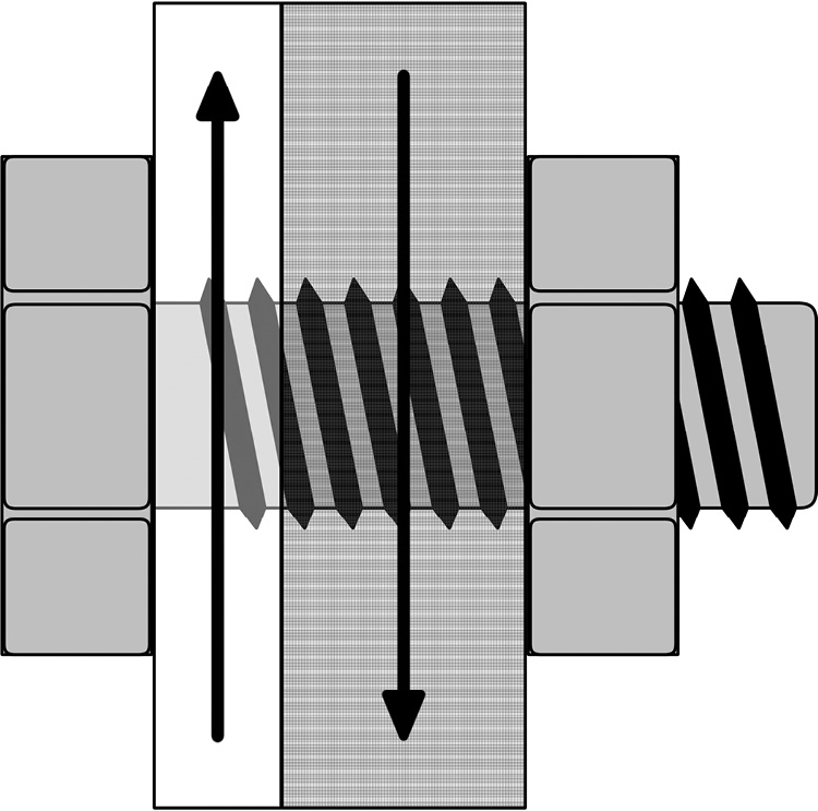
Figure 17-24 Shear load forces on a bolt
• Tensile load, in which the load stretches the mounting fastener (see Figure 17-25), causing soft, inferior grade fasteners (like bolts) to stretch, distort, or break
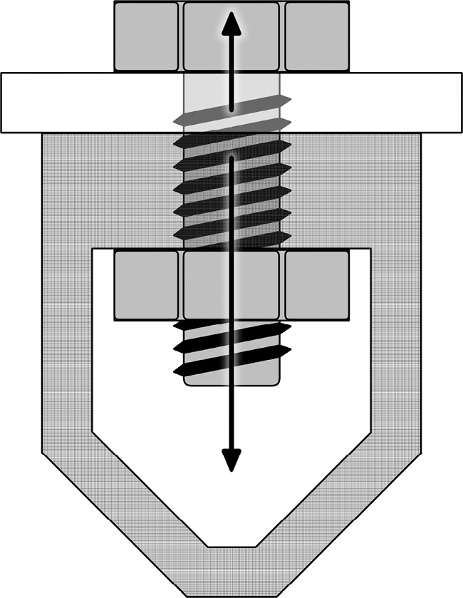
Figure 17-25 Tensile load forces on a bolt
• Pull-out, which refers to the fastener pulling out of the structure, wall, or ceiling from which it is mounted (see Figure 17-26)
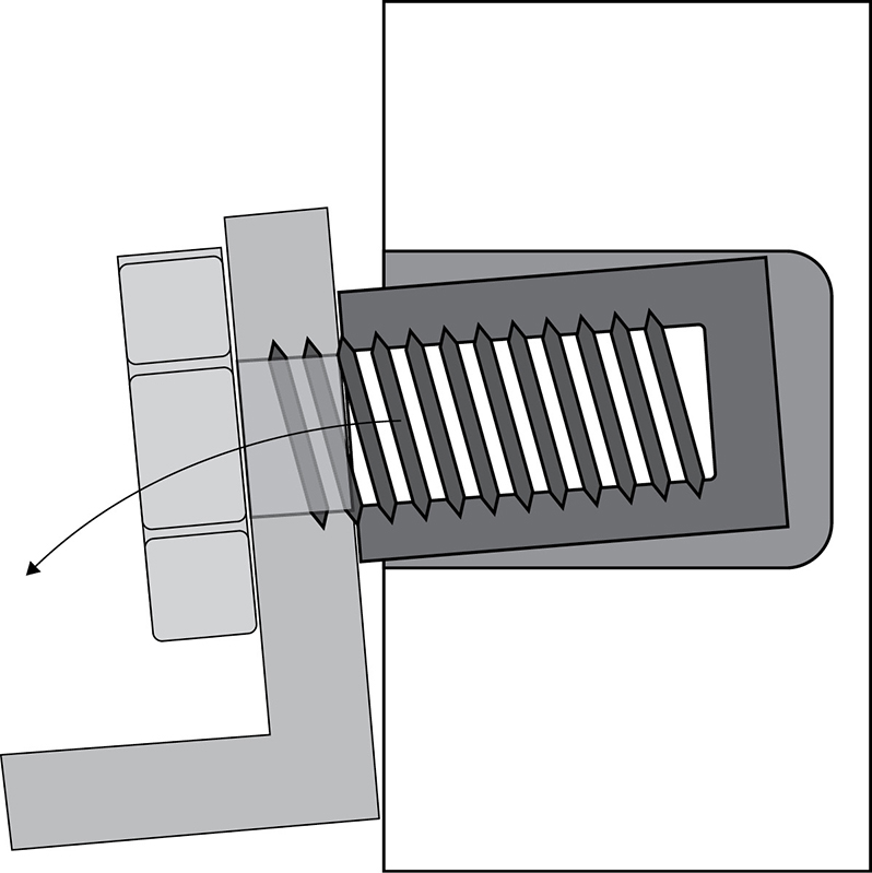
Figure 17-26 A bolt pulling out of a wall
• Shock loading, which refers to a sudden additional load, such as from an earthquake or a person hanging from a mount
• Bolts placed at the top of the mount carry more stress than those placed at the bottom (since not all fasteners carry the same the load in a mount), although following the manufacturer’s instructions for placement should avoid this problem
Mounting Safety Tips
Safety first! It is always important to define the elements of the mounting solution you plan to employ and to use rated hardware and components. Then do the following:
• Review the size and weight of what you will be mounting, including all brackets, mounting components, and hardware.
• Verify the exact mounting location.
• Inspect the structure to which you will be mounting the AV component and assess any potential problems.
• Review and follow all manufacturer guidelines and drawings.
A structural engineer should review all mounting plans and advise on any problem situations you may encounter. You should also have a licensed engineer sign off on any custom or modified mounting components you intend to use. When in doubt, always ask for help. Keep in mind that if you modify another contractor’s work, you become responsible.
Preparing to Mount an AV Component
The general process for mounting AV equipment is similar, regardless of the equipment itself. To prepare for a standard installation, make sure to do the following:
• Determine the proper location for the component from the designer’s drawings and specifications.
• Analyze the feasibility of mounting at the location, including locating any preinstalled structural blocking, cable pathways and terminations, and designated electrical and/or data outlets (if required).
• If the AV design stage did not include a site survey to evaluate the structural integrity of the proposed mounting location, determine whether the mounting location is suitable for the intended mounting solution. Consult a professional engineer if you have doubts about the strength of the structure.
• If the installation is not based on a detailed site survey and system drawing, you, as an AV installer, may be called on to make decisions in the field. An installer must decide on the proper mounting method by inspecting the structure to which the mount will be fastened, and verify that the building structure will properly support the total weight of the equipment and its mount. The installer must also determine how to route cabling to the equipment, provide for any required electrical supply and/or data feeds, and evaluate issues such as how a service technician can gain access to the device for maintenance.
• Familiarize yourself with the mounting hardware and procedure. For example, a typical flat-panel display mount comes in two separate pieces: the wall bracket and the equipment bracket. These come together to hold the flat-panel display on the wall. Installers should use only premanufactured mount assemblies and should not attempt to create custom mounting devices in the field.
• Make a list of the tools and materials needed to mount the equipment at the determined location. Be sure you have everything before you start.
• Secure the area around the construction zone for safety. Clear ample space in which to perform the installation. Construct personnel barriers and remove furniture that is in the way or could be damaged. Cover other furniture or equipment to protect it from dirt, dropped material, and so on.
Each type of AV equipment has specific installation and mounting requirements. Here, we’ll look at the installation of some common components.
Mounting Projectors
An AV technician must carefully position and align a projector relative to the projection surface or screen. Use the information supplied by the projector manufacturer to determine whether the desired mounting position is within range of where it should be located for correct display. The manufacturer’s information will include measurement distance (or range of distances for a zoom lens) from the projection surface to a reference location on the projector. It will also provide information about the correct position for the projector relative to the top (or center or bottom) of the screen.
There are four basic orientations for a projector.
• A projector can sit upright on a table or cart in front of the projection screen (default orientation).
• A projector can be inverted and mounted to the ceiling (on the same side of the screen as the audience). Figure 17-27 shows a technician installing a mounting bracket on a projector for mounting it to a ceiling (image inverted).

Figure 17-27 A projector with a ceiling mount
• A projector can be located behind the screen (in a rear-projection configuration with image reversed) in either a bottom (floor-mounted) or top (image inverted) orientation.
Once a projector is physically positioned a certain way, it must be adjusted so it projects an image that appears in the correct orientation. You typically adjust image orientation via a menu accessed through the projector’s control interface.
Mounting Projection Screens
Projection screens should be located and mounted so that they will not cover any alarm indicators, thermostats, clocks, light switches, or power and data outlets. Additionally, a retractable screen should hang flat, clear of any wall-mounted furniture, marker trays, and other items in the area.
Electrically operated roller screens have limit switches, which are physical switches that turn off the motor. Make sure you follow the manufacturer’s instructions for setting the up-limit switch, which prevents the screen from retracting too much, and the down-limit switch, which limits how far the screen extends.
Mounting Loudspeakers
Loudspeakers are available in models designed for mounting directly to a ceiling or in enclosures with manufacturer-installed mounting points that enable them to be suspended from an overhead structure or surface-mounted on an overhead structure or wall. When mounting loudspeakers overhead, use only loudspeakers with enclosures designed for that type of application.
Best Practice for Mounting Projectors
When mounting a projector, check the structure for vibrations by resting your hand on the surface to which the projector will be mounted. Sometimes, a heating, ventilation, and air conditioning (HVAC) unit is located on the roof above, creating vibrations that will transfer to the projector, causing images to appear unfocused. If you detect vibrations, you’ll need to find a solution.
It’s a good idea to check for structure-borne vibrations at the time of day when the AV system will typically be in use and with all normal building systems operating.
Mounting Flat-Panel Displays
Flat-panel displays are typically mounted to walls, as shown in Figure 17-28, or hung from an overhead structure using a mounting bracket. These displays can be heavy, so it is important to ensure that the surface on which they are mounted is strong enough to support the weight of the display and its mounting hardware.

Figure 17-28 Mounting a flat-panel display
Wall reinforcement by the builder is often required for mounting heavy equipment. This is the process of fixing additional heavy timber pieces between two or more studs in the wall cavity prior to applying wall material and finishes. That way, the wall structure is strong enough to support the weight of the equipment. Reinforcement should be handled before the wall finish is applied, because doing so after may incur extra cost to take apart and repair the wall.
NOTE Wall reinforcement can be accomplished only through planning and coordination among the AV designer, installer, architect, and builder. This illustrates the importance of paying attention to the installation needs of an AV system before construction has begun. Ignoring such needs can be messy and costly.
Finalizing Mounting
Once you’ve mounted your client’s AV equipment, finalize it as follows:
• Connect the appropriate signal, control cables, and electrical power (if required).
• Adjust the equipment to operate properly within the user’s environment.
• Thoroughly clean up the site, including these tasks:
• Remove all construction debris.
• Remove all packing material from the client’s premises.
• Retain all installation and operational instructions for inclusion in the system documentation package.
• Replace all equipment and furniture.
• Pack up and return all tools and leftover materials to where they belong.
• Remove personnel barriers.
Setting Up and Configuring AV Control Systems
Modern network-based control systems are powerful and complex. Control system installation follows preparation guidelines that are similar to those for other audio and video systems. However, the complexity of control systems requires special attention to system details, including functional design, signal-flow drawings, IP or other addressing information, and other technical documentation. To install the system correctly, the AV installer will often need to consult with the software programmer, system designer, and IT professionals involved in the project.
All AV control systems must be accompanied by a design that includes a button-by-button operational specification for all required touch panel(s), as shown in Figure 17-29, and other user interfaces. As described in earlier chapters, the AV team should consider the users’ needs and work with the programmer to identify how devices will be used and how they will connect to and interact with the control system.
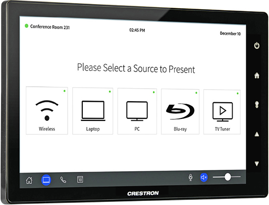
Figure 17-29 A control system touch panel (courtesy Crestron Electronics)
AV professionals should do as much of the control system configuration and testing in the workshop as possible. Troubleshooting a control system on a job site can be challenging. Verifying settings and the correct operation of the control system in the workshop allows you to interact with everyone involved in the project. You can verify touch panel designs and troubleshoot issues in less time when configuring a control system in the workshop. Ultimately, there are fewer disruptions for programmers to work around, and clients get a functioning control system in a shorter period of time.
However, because of project deadlines and the need to test connections with the client’s equipment and systems, working at the shop is not always possible. An AV professional will need to configure and test some items on the job site, although an efficient installation plan can keep this to a minimum. When outside contractors are engaged to program the system, close coordination is essential.
Termination for Control Systems
To correctly terminate control system wiring, the installer needs technical documentation indicating which connector(s) to use, pinout and gender for the connector(s), and the type of signal the system will carry. Some protocols are associated with specific connectors, but that’s not always the case. Improperly terminated pinout connectors can ruin an installation and compromise a design through loss of functionality.
Common signal types and related terminations for control systems include the following:
• Ethernet is a bidirectional signal type. Wired Ethernet connections typically use either twisted-pair Category cable, terminated with an 8P8C or RJ-45 connector, or fiber-optic cable. Ethernet signals may also be transmitted wirelessly via RF. The base standard for wireless Ethernet connections, commonly known as Wi-Fi, is IEEE 802.11, with the specific version labeled as Wi-Fi 1, Wi-Fi 2, etc., as detailed in Chapter 6.
• RS-232 is usually terminated with a DB-9 connector. It is often bidirectional and uses an unbalanced connection. You can use RS-232 to send commands from a control system or a computer to an AV device and receive feedback (responses) from the device. Bidirectional signal flow is preferred over unidirectional flow because it enables equipment to provide confirmation of its status and/or that an action has been performed. You need to configure RS-232 for proper speed and other connection parameters, which depend on the connected device.
• RS-422 is usually terminated with a DB-9 or DB-25 connector and uses a balanced connection. Operating over a balanced connection enables RS-422 to work over greater distances than RS-232 because balanced circuits benefit from common-mode rejection.
• RS-485 is usually terminated with a five-pin XLR type connector when used for the DMX512 lighting and effects control protocol. RS-485 is a bidirectional, balanced transmission-line signal that supports up to 32 daisy-chained connections. It requires 120-ohm terminations at both ends of the transmission line.
• USB is bidirectional and is used both for control and AV content. It is terminated in a range of standardized connectors (Types A, B, and C) associated with various versions of the protocol (1.2, 2.0, 3.0, 3.1, 3.2). Small form-factor versions (mini and micro) of the Type A and Type B connectors are also in use on portable devices. USB versions 3.0 and later are generally not considered to be candidates for field termination.
• RF is used mostly for user interfaces. It is susceptible to interference, so you should conduct on-site tests to confirm its reliability. This signal type can be unidirectional or bidirectional.
• Ramp voltage is an infinitely variable analog voltage for which there is no standardized connector type. Essentially a legacy analog control protocol, it was mainly used for controlling things like projector lenses, pan/tilt/zoom on camera lenses, architectural lighting, and volume controls.
• Relays and contact closures are binary controls, which are either on or off. A closed relay (with voltage) or contact closure (no voltage) passes a signal, and an open relay stops a signal. Relays are commonly used to execute simple on/off, open/close, or up/down commands, while contact closures usually monitor the status of something with only two states.
Assembling the Control System
Many devices in the AV industry are connected to corporate data networks or other hybrid networks. Most of these devices communicate with each other using the TCP/IP protocol over Ethernet and require IP addresses.
Setting up network-based control systems can be a challenge. For networked control signals to find their destinations, each device must have a unique identifier—either an IP address or a DNS hostname. You should work with the client’s IT manager to determine which devices can be connected to the client’s network. After that, you will continue to work with the IT staff to assign IP addresses or DNS hostnames to the devices.
Start by providing a list of network-connected AV and control system devices to the client’s IT manager for review. The list should include the device, manufacturer, model number, MAC address, software and firmware versions, and intended location. It may also briefly explain why each device needs network connectivity and how much bandwidth it will require. Leave space on this list for the IT manager to write in the IP address or DNS hostname of each device. Make sure the IT department doesn’t have network security or bandwidth concerns with any of your gear. The IT manager will appreciate the advance notice, and you’ll be able to work out any issues early.
Once the gear is approved, you can ask the IT manager to assign an address or DNS hostname to each device. If your devices require static IP addresses, ask the IT manager to reserve them and add the assigned addresses to the list. If your devices support DNS, you won’t need permanent addresses. Instead, devices will find each other using their permanent DNS hostnames. They will be assigned an address dynamically whenever they need to connect. In this case, ask the IT manager to create a DNS record for each device and add the domain name to the list of networked devices.
Once you’ve determined how devices will be identified on the network, you’ll need to configure each device to respond to its new IP address or DNS hostname. The most common methods to achieve this are through a dedicated configuration application running on a directly connected computer or over a network via the device’s internal web interface. When in doubt, refer to the documentation for each piece of equipment in the system.
After setting the address, mark the setting on the back of the device for future reference at the job site. Not only will this help if there are several pieces of the same model to install, but it also makes it easy to determine which settings have been established on each device without needing to search through menus.
After you have correctly configured all devices (including defining whether the IP address is static or dynamic), you should verify network connectivity. One way to do this is to ping the device, usually through your operating system’s console window. This will show if the target is online and accepting active connections. Other console command-line prompts can help verify the network status and settings of a device.
To verify the IP address of a control system CPU, an installer can typically connect a computer to the CPU, or the network it is connected to, and perform checks per the manufacturer’s instructions. Another method may be to select a menu option on the front of the CPU, which will display the IP address on the unit’s screen.
Using Control System Software
A control system is similar to a computer: it must include software to operate. You can install hardware devices and wire the system, but until firmware and software are loaded, the system will not function.
Firmware is the CPU’s operating system—a bit like Windows, macOS, Linux, iOS, or Android. Most firmware is specific to the make of the control system, but a few use Linux or another multipurpose operating system.
The software is a unique application written for a specific AV installation. Some applications are preprogrammed, and others are programmed especially for the client. There are separate software programs for the controller and the touch panels/button controllers (the interfaces). Each type of program must be installed on its respective device. The manufacturers of the devices may have proprietary computer programs for installing software on their devices. Refer to the control system’s software documentation for the installation process.
Don’t forget to ask the software programmer if there are any “hidden pages” in a touch panel graphical user interface (GUI). Hidden pages are unseen hot spots on a touch panel that allow the technician to configure passwords, autopowering, and other settings. Any hidden pages should be included in the documentation provided by the designer. Asking about this can save you time in configuring the system and training the client.
Testing and Installing the Control System
Once each device in the AV system has been inspected and configured, connect the control system and controlled equipment as completely as possible at the workshop. Test each button on every touch panel for proper operation while referencing the button-by-button design documentation. Also, document any problems and report them to the software programmer or the designer. Any problems you can resolve in the workshop will make on-site installation easier.
It is imperative that the full functionality of the system be well known; otherwise, testing of the system may not be complete. It’s possible that the software programmer has added a feature or has not included a feature.
After arriving on site, use the design documentation to confirm the locations of all the control devices in the room. Note any inconsistencies discovered during the installation process for future reference on drawings and/or for making software revisions.
Final Control System Testing
Once you’ve installed the control system at the job site, test it as follows to ensure proper AV system functionality:
• Verify that all cables are connected correctly and according to the drawings. Modify drawings or connections as needed.
• Power on the control system CPU, peripherals, and user interfaces, plus the attached AV equipment.
• Verify that all appropriate device-selection buttons are available on the user interface(s). For example, if you touch the button for a media player, check that the switcher activates the correct input.
• Verify that the correct buttons appear for the operation of each device you select. For example, if you touch the button for the media player, then the appropriate controls, such as play and pause, should appear on the touch panel.
• Confirm that each device action button performs the specified action in accordance with the button-by-button specification.
• Test all wall buttons, control switches, motion and IR sensors, and all other devices that interact with the system. This process can take several hours. Remember that some control buttons may be programmed to perform more than one action or have conditional responses based on previous actions.
After you’ve completed testing and resolved any issues, the client should have a reliable, fully functioning control system that performs as specified in the designer’s documentation.
Configuring Networked AV Systems
We’ve touched on one AV application that commonly traverses an IT network: the control system. But these days, many more AV systems rely on IP and enterprise networks to function. Assuming you’ve coordinated the design of your AV system with the client’s IT staff (see the section on integrating with IT networks in Chapter 16), you may need to take several steps to configure your AV system to operate on the client’s network.
Keep in mind, what follows must also be addressed during the design phase, in coordination with the client’s IT department. Issues regarding subnetting, IP addressing, VPN and VLAN requests, and LDAP integration will have been hashed out and settled before installation. But during installation, you will need to coordinate with the IT staff to ensure that networked AV devices are configured properly to operate on the network as they were designed to work.
When setting up an AV system to operate on a client’s network, work with the IT department to configure subnetting, VLAN, VPN, and IP addressing, as necessary for the particular AV system design. Because networked AV systems are relatively new to AV professionals, it may help to review the network essentials covered in Chapter 6.
Subnetting
As networks get bigger and the systems attached to them become more bandwidth-hungry, subdividing the network becomes important. Real-time media, particularly video, has an appetite for bandwidth. Fortunately, IP networks have a built-in subdivision mechanism: the subnet. IP networking uses two addresses to identify the system: the IP address and the subnet mask. By altering the subnet mask, a single physical network can be transformed into many logical ones.
Subnetting doesn’t reduce bandwidth consumption, but it does help isolate it, limiting broadcast traffic to devices within the same subnet.
NOTE A subnet mask is a binary number whose bits correspond to bits in IP addresses on a network. Bits equal to 1 in a subnet mask indicate that the corresponding bits in the IP address identify the network. Bits equal to 0 in a subnet mask indicate that the corresponding bits in the IP address identify the host. IP addresses with the same network identifier bits as in the subnet mask are on the same subnet.
VLANs
Sometimes clients want certain users to have access to their networked AV traffic, but not to their other resources. For example, a law firm may want to give its clients access to its videoconferencing system, but not its file servers. In such cases, you need to be able to subdivide your subnets. VLANs provide a means for this subdivision and allow the AV system to leverage an enterprise’s existing network infrastructure, while still preserving its bandwidth and network security.
Because VLANs are not related to the network’s physical topology, devices on the same VLAN can be located anywhere on the LAN. Also, while a device can belong to only one subnet, it may belong to multiple VLANs. On many devices, a VLAN can be configured with an access control list, which specifies the devices allowed to access the VLAN or the devices the VLAN is allowed to access. The former protects data on the VLAN; the latter keeps devices on the VLAN from being used as a launching point for attacks.
Implementing a VLAN can be labor-intensive because the VLAN broadcast domain must be segmented on every switch in the network. The network administrator must specify the MAC address, port, or IP address of every device on the VLAN, on every switch in the network.
A VLAN is a bit like a “friends and family” long-distance calling plan. Devices that need to “talk” frequently get efficient, unfettered access to one another. Their access to devices outside their VLANs, however, is slower and may be limited or even blocked. Because the communication among devices on a VLAN is typically switched rather than routed, it’s efficient. Digital signage, for example, is well suited to a VLAN.
Requesting a VLAN
If you determine that an AV system should be segregated on a VLAN—for its own good or for the good of the network—you’ll need to provide the network manager with the following information:
• What VLAN you want to create and why (for example, “I want to create an IPTV VLAN so that the network isn’t flooded with streaming video traffic”)
• Which devices should be included in the VLAN
• Whether any routing between the VLAN and other network locations should be required or permissible
NOTE A broadcast domain is a set of devices that can send Data Link layer frames to each other directly, without passing through a Network layer device. Broadcast traffic sent by one device in the broadcast domain is received by every other device in the domain.
VPNs
Almost any large or physically dispersed organization will require some way to hold managed communication between its LANs. This may also be true of networked AV systems that span multiple LANs, such as unified communications (UC) systems.
Services that are especially necessary for AV applications—such as QoS, low latency, managed routing, and multicast transmission—are impossible over the open Internet. Customers and service providers also commonly need a secure means of accessing systems remotely for monitoring, troubleshooting, and control purposes. VPNs provide a way.
A VPN may be able to secure UC streams between offices, but be aware that using a VPN increases required bandwidth overhead. This is because an encryption and tunneling wrapper must be added to each network packet that travels across a VPN. This additional overhead may not be significant in terms of bandwidth requirements, but it can increase the Ethernet frame size to the point where packets must be fragmented before they can be sent across the network. Packet fragmentation can be disastrous for the quality of streamed video or conferences. Always be sure your frame size is set low enough to account for VPN overhead. A VPN may also increase signal latency for UC.
IP Addressing
When connecting an AV system to an IP-based network, you must carefully consider how networked devices will be assigned IP addresses. A control system, for instance, must be able to consistently locate each device it controls.
When installing your AV system, you may be limited to whatever addressing scheme the client already uses. The following are the main IP addressing schemes, each of which has benefits and drawbacks: DHCP, DNS, and static addressing.
• DHCP This approach allows network administrators to automate address assignment. When a device connects to the network, the DHCP service or server will assign an IP address to the device’s MAC address. The pool of available IP addresses is based on the subnet size and the number of addresses that have been allocated. DHCP is easy to manage because no two devices get the same address, relieving potential conflicts. It also allows more devices to connect to the network. However, with DHCP, you never know what a device’s IP address will be from connection to connection. Blocks of IP addresses can be omitted from the DHCP pool to use for statically addressed devices.
• Static IP addressing This approach assigns fixed IP addresses to networked devices. Many AV devices must always have the same address so control and monitoring systems can find them. In the absence of a DHCP server, you will need to manually set the IP address (which you must obtain from the IT manager), hard-coding it onto each device. To do this, you will need the IP address, the subnet mask, the device name, and the DNS server and gateway addresses.
• Reserve DHCP This is a hybrid approach to IP addressing. Using reserve DHCP, a block of statically configured addresses can be set aside for devices whose IP addresses must always remain the same. The remaining addresses in the subnet will be assigned dynamically. To reserve addresses for AV devices, you need to list the MAC address of each device that requires a static address.
TIP If the client has a DHCP server, it’s better to use a hybrid approach than manually assigning an IP address to every AV device.
• DNS This approach uses a hierarchical, distributed database that maps easily remembered names to data such as IP addresses. A DNS server keeps track of all the equipment on the network and matches the equipment names so they can be easily located on the network or integrated into control and monitoring systems. Many AV devices don’t natively or fully support DNS address assignment.
Producing AV Events
AV installers may also be required to set up and configure AV equipment in a temporary setting to support a presentation or performance. This task requires the installer to be able to do the following:
• Transport equipment to the site safely
• Set up and operate the temporary AV system
• Dismantle and pack up the temporary system
• Remove the system after the event
Here, we will look at some of the main concerns when installing AV equipment to support a small-scale temporary event. The production of large-scale AV events is outside the scope of the work for a CTS-qualified technician.
Preparing for the Event
Properly preparing for the event is critical. This includes the following tasks:
• Reference the system designs (sound, visual display, lighting, staging, and so on) and create a checklist of required equipment and cables.
• Ensure that all equipment on the checklist is tested as both safe and fully operational before it is transported to the event.
• Allocate enough crew resources with the appropriate skills and credentials/licensing for the project, as well as other resources, such as transport, additional equipment, tools, materials to be hired, permits, and so on.
• Identify where you are going and where to park when you arrive. You may need to ensure access to a loading dock or service entrance.
• Create a realistic setup, testing, plotting, and rehearsal schedule so everything will be ready for the event start time.
Loading and Unloading a Truck
Working with equipment in and around trucks can be dangerous. Be sure to read your company’s guidelines concerning safety and follow them.
Loading Equipment
The following are some of the typical safety guidelines when loading equipment on a truck:
• Do not move awkward or heavy items by yourself.
• Bend at the knees when lifting items, and follow proper lifting procedures.
• Follow all safety guidelines when using high-level access equipment, forklifts, or other lifting equipment. Ensure that only appropriately-licensed personnel operate these and other types of specialized equipment, as defined in applicable codes and regulations.
• Never leave an item in an unsecured position where it may slide forward and distract or injure the driver. Use load restraints, safe stacking practices, and proper truck weight distribution to prevent the load from shifting during transit.
• Do not leave road cases resting on their wheels. Turn the cases on their weight-bearing side to prevent the cases and the wheels from becoming damaged and to make the load more stable. If it is not possible to leave a case on its side, use loading bars and straps to secure the case, and lock the wheels in place.
• The use of carts and dollies can make moving equipment safer and faster for everyone. Strap items to carts and dollies to prevent them from sliding off when being moved over bumps and along ramps. Do not overload the cart or dolly.
• Be familiar with the load limits of the truck or trailer you are loading and the total weight of the equipment you plan to load. There are laws regarding the safe operating weight of your vehicle. Know your company’s rules to avoid liability issues.
Unloading Equipment
When you arrive at the venue for the event, consider these procedures when unloading a truck (see Figure 17-30):
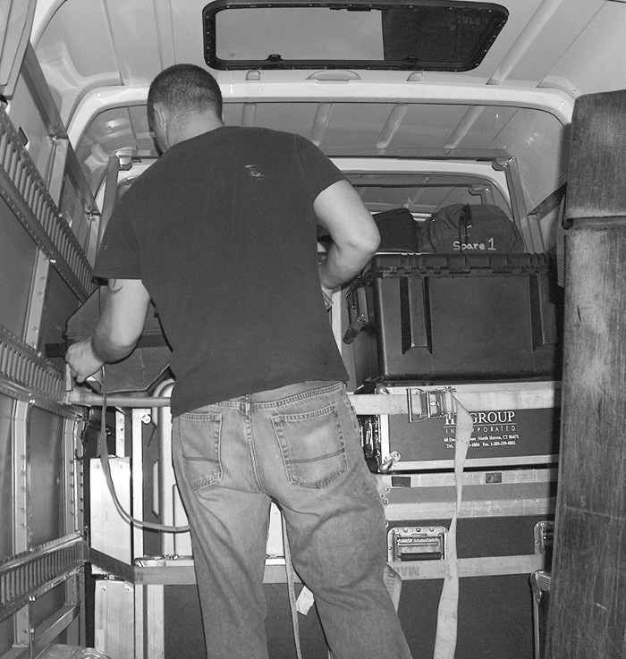
Figure 17-30 Unloading a truck
• Identify the area where the truck will be unloaded and make sure you have approval to unload the truck in that area.
• If you are using a loading dock, use dock plates laid over the gap between the truck floor and the loading dock. You may also use dock lifts that raise or lower the dock to match the height of the truck, or lift-gate platforms installed on the back of a truck for lowering heavy items to the ground.
• If a loading dock is not available, use truck ramps to bridge the gap between the truck floor and the ground, the truck’s lift-gate platform (if fitted), or forklifts to bring palletized loads from the truck to ground level. To prevent damage to equipment cases, the loads should be secured to pallets before being loaded into the truck.
• Inspect the route you will use to reach the event space to make sure that large items will fit through doorways, hallways, and elevators.
• Determine if there are any special requirements to protect flooring, walls, and doors when moving equipment through the site.
Setting Up Equipment
An AV installer may be called on to set up equipment to support the event. This equipment may include pipe-and-drape backdrops, lighting, audio systems, projectors and screens, folding projection screens, and flat-panel displays.
Pipe and Drape
Pipe and drape is commonly used in an event space as a backdrop for a stage. This arrangement can hide unsightly areas where equipment cases and cabling are stored, add texture and interest to an event, or serve another purpose.
Setting up pipe and drape can be hazardous and requires at least two people (see Figure 17-31). The floor bases are very heavy and can injure you and damage floors. Poles can fall over and strike people and props. It is easy to trip and fall on the drape panels. The safety of all personnel involved should be a priority.
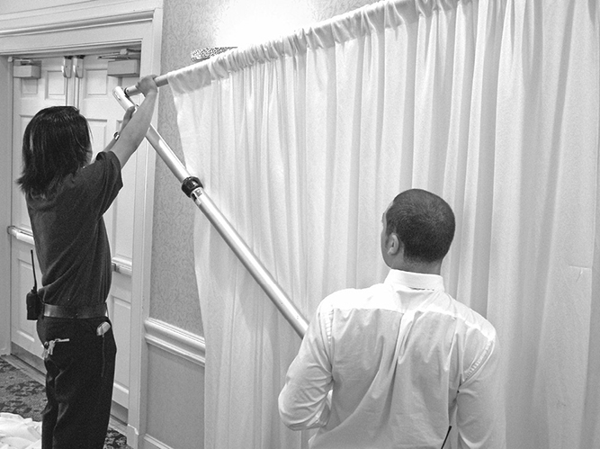
Figure 17-31 Installing pipe and drape
Sound-Reinforcement Systems
Sound-reinforcement systems include loudspeakers, amplifiers, and a mixer to blend and distribute various sources, including multiple microphones, media players, optical disk players, and computers.
Typical tasks for setting up sound-reinforcement systems include the following:
• Place or hang the loudspeakers on either side of the visual display area, taking care to put them in front of all microphones.
• Place each microphone directly in front of the positions from which persons will be speaking. To help minimize feedback, do not place microphones in the area in front of the loudspeakers. Microphones should be pointed toward the presenters’ mouths, so they speak from above the microphone, not directly into it.
• Set up the mixer and outboard equipment on a table at the back of the room so that you can observe all the microphones and hear the mix in the same way as a member of the audience. Label inputs so that you know what each channel controls.
• Connect all cables and power on all equipment except the power amplifier. Set initial signal levels and test all inputs. Turn the power amplifier inputs to zero (fully attenuated) and power on the amplifier. Slowly bring the levels on the power amplifier up until the proper level is achieved.
• When testing and troubleshooting is complete, properly tape down all cables, following the best practices for laying tape over cables on the floor, as shown in Figure 17-32, or use cable protector ramps as shown in Figure 17-33.
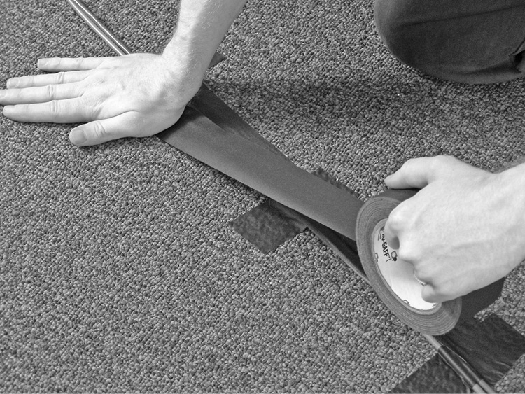
Figure 17-32 Taping cables to the floor
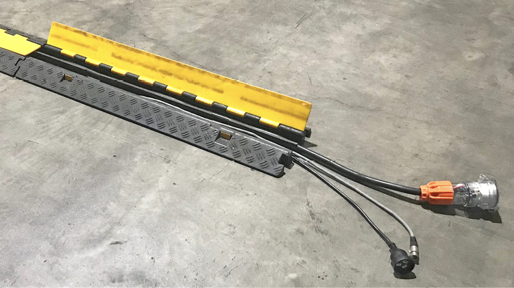
Figure 17-33 A cable protector ramp (courtesy Resolution X)
Projectors and Screens
You should set up projectors and screens to produce an optimal viewer experience. The size of the screen and the type of lens on the projector determine how far away the projector should be from the screen. This measurement is called the throw distance.
Here are some guidelines for installing projectors and screens:
• Calculate the appropriate throw distance for your specific projector by multiplying the screen width by the lens zoom ratio. For example, if your screen is 3 meters (10 feet) wide and your lens ratio is 2.0, the distance from the screen to the projector is 6 meters (20 feet).
• If the projector will be mounted on a table, plinth, or cart, check to see that no audience chairs are located immediately next to the projector’s location. Projectors may generate heat and fan noise, which is distracting for attendees.
• Verify that there is adequate space for the projector. Areas around the projector should have good ventilation and not trap heat. If a projector overheats, it will automatically shut down until it has cooled.
• Place the projector table, plinth, or cart at the desired location, and place the projector on the surface, securing it with a security cable to prevent theft, if necessary.
• Run all necessary cables to the projector’s location and connect them. Note that some larger projectors require substantial power, so it may be necessary to use a separate power circuit.
• Send a test signal to the projector from a computer or video player.
• Turn on the projector. It may take several minutes before there is a usable image.
• Verify that you’ve selected the correct input on the projector. The projector may have an auto-detect or auto-image button, or you may need to toggle through several inputs.
• Verify that the projected image is neither inverted nor reversed.
• When the image is displayed, center and level the projected image on the screen by adjusting the projector’s legs. Review the projector setup instructions for information about specific adjustments.
• Use the projector’s zoom and focus features to fill the screen with the displayed image, at least from side to side. If you cannot place the projector in an optimal location, as a last resort, you may need to use the keystone features on the projector to make the image square on the screen.
• Walk around the seating area to see if the image appears to be focused and square from the audience’s point of view.
Folding Projection Screens
Folding projection screens have a flexible fabric screen surface, which is snapped or laced to a rigid, four-sided metal frame. There are two types of screen fabrics. One type is used for front projection, when the projector is in front of the screen with the audience. The other type is used for rear projection, when the projector is behind the screen. Because the surface is a stretched fabric, folding screens are extremely flat, so creases should not be a problem.
The screen frame is usually a single, jointed structure that unfolds to form a rectangle of a fixed size. The frame is mounted on folding legs. These screens are commonly used with a black skirt and side curtains, giving the appearance of a portable theater environment. Folding screens are available in much larger image sizes than tripod screens.
Flat-Panel Displays
Flat-panel displays are typically set up on a stand or mounted to a vertical surface, such as scaffolding or truss.
Here are some guidelines for installing flat-panel displays:
• Study the area where the flat-panel display will be located and verify that there is no restriction of airflow to the panel.
• Determine the safety of the audience and the equipment if it were placed in the proposed location.
• Ensure that the proposed location is flat and level.
• Verify that the audience can see the screen.
• Determine the possible pathway for running signal and power cabling and locate the designated electrical outlet.
• Assemble the stand or mount.
• Carefully lay the display face down on a flat, clean shipping blanket. Make sure there are no tools or other objects under the blanket to damage the panel.
• Connect the mounting bracket to the display. Use only the premeasured mounting bolts that are specified for attaching to that particular make and model of display. Using screws or bolts that are too long or have the wrong thread will cause damage, potentially destroying the flat-panel display.
• If you are using a base with a vertical post, set up the base following the manufacturer’s instructions. If you are mounting the panel to scaffolding or truss, make sure a certified rigger has constructed the structure.
• Mount the base bracket to the vertical post or scaffolding following the manufacturers’ instructions (see Figure 17-34). Before tightening the hardware on the base bracket, ensure it is at the correct height and is level.

Figure 17-34 Mounting a small flat-panel display on a truss
• With a partner, carefully raise the flat-panel display to the base bracket and connect the two brackets. During this process, avoid putting pressure on the delicate surface of the image area.
• Run all electrical and signal cables to the panel and connect them.
• Using a video test pattern, verify proper operation of the unit, making electronic adjustments as necessary.
• Clean up the area by picking up all tools, equipment, packing material, and storage cases.
Supporting AV Systems
In many cases, the level of expertise required to maintain a complex AV system is beyond the skills and knowledge of personnel in the client organization. In these cases, clients may be interested in obtaining ongoing support from the AV vendor.
AV vendors can typically provide several types of support services:
• Maintenance and repair AV equipment or installation infrastructure may fail, requiring troubleshooting and repair services to return the system to full operation. The AV vendor that provided the installation services is often requested to supply ongoing maintenance and repair services, since this company has the best understanding of how the system was designed and installed.
• System updates As the needs of the client expand or change and the capabilities of AV technology increase (or reduce in cost), clients may want to update their AV systems. For some clients, updates can be on a regular, ongoing basis.
Keep in mind that offering support in each of these areas may be important to establishing a long-term working relationship with clients. They will come to view your company as a long-term partner in meeting their AV needs, rather than a one-time design or installation vendor. You will learn much more about supporting clients in Part V of this book.
Chapter Review
AV technical professionals must be able to install a wide range of AV equipment and systems at the client site. This task requires that the AV professional be able to read and understand AV system design documentation, know how to physically install AV equipment, and know how to configure the individual devices to operate as intended within the overall AV system.
In this chapter, you reviewed some of the basic tasks and procedures involved in installing an AV solution in a technically correct and professional manner, following design specifications created for the customer systems. You may need to interconnect devices and fabricate system elements, such as cabling, mounting components, and equipment racks. We discussed setting up and configuring individual AV devices, integrating them with a control system, and configuring them to operate on a network, where applicable. We also covered setting up AV equipment for temporary events and providing support for installed AV systems.
Review Questions
The following review questions are not CTS exam questions, nor are they CTS practice exam questions. These questions may resemble questions that could appear on the CTS exam but may also cover material the exam does not. They are included here to help reinforce what you’ve learned in this chapter. See Appendix D for more information on how to access the online sample test questions.
1. Which of the following is a sign of an improperly fabricated cable termination?
A. Visible stray wires
B. Visible solder
C. Removed jacket or insulation
D. Crimping
2. What type of termination does the following picture show?
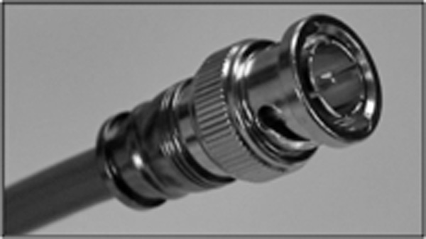
A. XLR
B. 8P8C
C. BNC
D. RCA
3. Which of the following tests should be conducted to evaluate whether a termination is properly transmitting a signal?
A. Voltage test
B. Continuity test
C. Signal sweep test
D. Isolation test
4. To communicate with devices installed onto a TCP/IP network, what must each device have?
A. An IP address
B. A wireless card
C. A web address
D. A TCP card
5. What is a drawback of using a rack-mounted RF receiver?
A. The metal rack can shield the receiver from its intended signal.
B. It relies on line of sight to the signal transmitter.
C. It operates on different frequencies than its receivers.
D. It is sensitive to fluorescent light.
6. Which of the following rack-ventilation methods uses a fan that draws air from the rack?
A. Convection
B. Pressurization
C. Conditioning
D. Evacuation
7. What does signal separation refer to within a rack layout?
A. Separating cables according to signal strength
B. Separating components according to signal type
C. Running several cables carrying the same signal to separate components
D. Splitting composite video signals into component RGB signals
8. When mounting heavy equipment, always mount to which of the following?
A. The building’s structural support or blocking
B. Drywall
C. Ceiling
D. Any stud in the wall
9. Who should evaluate all mounting plans and advise the installation technician on difficult mounting situations?
A. Structural engineer
B. AV manager
C. Mechanical contractor
D. Client
10. What is the load limit?
A. The maximum weight of an equipment rack
B. The highest intensity a sound system can produce
C. The weight at which the item will structurally fail
D. The tendency for an equipment rack to tip over
11. Roof-mounted HVAC systems may produce vibrations that cause the projector to vibrate and cause an image to appear unfocused.
A. True
B. False
12. To what does the permissible area of a conduit refer?
A. The locations within the ceiling where the conduit may be run
B. The outer diameter of the conduit used for specific applications
C. The amount of the inner diameter of a conduit that may be filled with cable
D. Conduits must be rated as fireproof when used within ceiling (plenum) spaces
13. What is the main purpose for reviewing the system design when preparing for providing AV support for a live event?
A. Allows the AV team to brief the presenters or performers on the capabilities of the AV system
B. Ensures that the system meets building code or regulation requirements
C. Helps the AV team integrate the live AV support with any broadcasting requirements
D. Helps the AV installer determine the required equipment and crew resources
14. Why can implementing a VLAN be labor-intensive?
A. Its broadcast domain must be segmented on every switch in the network.
B. You may be limited to whatever addressing scheme the client already uses.
C. It increases bandwidth overhead by adding an encryption and tunneling wrapper.
D. You will need to manually set IP addresses for each device.
15. Which of the following objectives should the AV team target when locating microphones for a live event?
A. Ensure that all microphones are behind loudspeakers
B. Ensure that all microphone cables are no longer than 15 feet (4.5 meters) in length
C. Ensure that all microphone cables are taped to the floor
D. Mount all microphones on nonconductive stands
16. How far away from the screen should you place a video projector with a lens ratio of 2.0 to create an image 3 meters (10 feet) wide?
A. 3 meters (10 feet)
B. 4.5 meters (15 feet)
C. 6 meters (20 feet)
D. 9 meters (30 feet)
Answers
1. A. Stray wires that extend outside the termination are a sign of an improper termination. A stray wire can cause a short that will interfere with system operation.
2. C. The termination depicted in the picture is an example of a BNC connection.
3. B. The AV technician should test continuity of the cable to determine whether it is properly transmitting signals or whether it is shorted in some manner.
4. A. An IP address is used to give each component on a TCP/IP network a unique address that allows components to communicate.
5. A. The metal rack casing and components can interfere with an RF signal transmitted from within a rack.
6. D. A ventilation approach that uses a fan to draw hot air from inside the rack is called an evacuation method.
7. A. Signal separation within a rack refers to grouping cables according to signal strength so that stronger signals will not create interference on cables carrying lower-level signals, such as power cables interfering with microphone cable signals.
8. A. Heavy equipment should be securely mounted, either using the building structural support elements or blocking installed behind the drywall specifically to be used as a mounting support.
9. A. Mounting plans for difficult mounting situations should be evaluated by a structural engineer familiar with the building’s structural elements.
10. C. The load limit rating refers to the weight at which the item will structurally fail. For example, the load limit on a flat-screen mount is provided to indicate the maximum weight that can be supported using the mount.
11. A. It’s true that HVAC systems can transmit vibrations that can adversely impact the quality of a projected image.
12. C. The permissible area refers to the amount of cable that can be run through a conduit, based on the outside cable diameter.
13. D. The installation team should review the system design to determine what equipment and materials are needed, along with the staff required to actually set up the system. It will also help the team determine how much time is required for system setup, which will aid in scheduling the installation tasks in a manner that meets the client deadlines.
14. A. Implementing a VLAN can be labor-intensive because its broadcast domain must be segmented on every switch in the network.
15. A. The AV team should strive to ensure that all microphones are mounted behind the loudspeakers to minimize any feedback.
16. C. You would place a projector with a 2.0 ratio lens 6 meters (20 feet) from the screen to create an image 3 meters (10 feet) wide.