
CHAPTER 4
Audio Systems
In this chapter, you will learn about
• The basics of sound propagation
• Sound wave frequency and wavelength
• Harmonics, the decibel, and the sound environment
• How these basics apply to the electrical pathway used to amplify sound
• The electrical audio-signal chain from start to finish—microphones to loudspeakers
• The various signal levels, cables used, and types of circuits that are preferred for professional audio
This chapter covers the basics of sound propagation, sound wave frequency and wavelength, harmonics, the decibel, and the sound environment. It examines how these basics apply to the electrical pathway used to process sound. We will review the analog electrical audio-signal chain from start to finish—from microphones to loudspeakers—and discuss the various signal levels, the cables used, and the types of circuits that are preferred for professional audio.
To understand sound, you should begin by understanding how your hearing works. As you can see in the figure in the color insert, your ears are complex organs that collect and channel sounds from the environment, convert the sound waves into mechanical movement, and then covert it into electrical signals that your brain interprets as sound information. Damage to any of these parts can reduce your ability to perceive sounds.
Sound Waves
Sound is the result of waves of compression moving through a compressible medium such as air or water. The vacuum of space is not a compressible medium—that’s why nobody can hear you scream.
The compression waves are generally caused by vibrations from an object such as a plucked string, a set of vocal chords, a loudspeaker, a tuning fork, a hammer hitting a nail, or even a cicada scratching its back legs together. Each movement of the vibrating object moves the medium around it, radiating alternating waves of compression followed by rarefication (decompression). Compression waves can also be caused by movements in the medium itself, such as wind blowing, a flute being played, or air escaping from a cooling vent.
A simple way to visualize these sound waves is to think of what happens when you drop a rock into a pool of water. The rock creates a disturbance by displacing water molecules—compressing them to create a raised-up wave, which then travels outward in the pool. As the wave peak travels, it leaves behind it an area of rarefication in the form of a trough, which in turn leaves behind it an area of compression, and so on. What we see is a series of concentric rings of peaks and valleys (compressions and rarefications) traveling outward from the point where the rock struck the water.
We will look at two properties that can be used to describe waves.
• Wavelength or frequency (which are directly correlated)
• Amplitude (height)
Wavelength
Wavelength is the distance between two points that occur at the same place in a cycle. If you select any point on the wave shown in Figure 4-1, the wavelength is the distance to the identical point on the next cycle.

Figure 4-1 Each of these waves is a single smooth sine wave. The amplitudes are identical, but the left wave is four times the wavelength of the right wave.
The central horizontal line is the zero-reference line or reference level, which represents the molecules at their rest position. The parts of the sine wave above the reference level represent molecules in compression, while the parts of the wave below the reference level represent molecules being separated (rarefaction).
A complete cycle has taken place when the molecules have moved from their rest position, through compression, then rarefaction, and back to their rest position. The wavelength of a sound wave is dependent on its speed of transmission through the compressible medium. For air, the speed of sound at sea level, at a temperature of 20°C (68°F), is 343 meters per second (m/s) (1,125 feet per second).
Frequency
Frequency is the number of wave cycles occurring in the period of a second—cycles per second. The standard unit for measuring cycles per second is the hertz (Hz). Figure 4-2 illustrates frequency.

Figure 4-2 Frequency is the number of cycles per second.
Although the sounds you hear every day are complex waveforms, every sound can be broken down into a series of individual simple sine waves at different frequencies. Fourier analysis is the mathematical process used to calculate what is known as the Fourier series of component frequencies for a waveform. The calculation and mathematical manipulation of the components of a waveform’s Fourier series lies at the heart of all digital signal processing (DSP) applications.
Frequency and wavelength are related to each other by the speed of transmission in a medium. In Figure 4-3 you can see the mathematical relationship between speed of transmission, wavelength, and frequency. Using these formulas you can calculate the wavelengths at the limits of the frequencies most humans can hear—20Hz to 20kHz.

Figure 4-3 The relationship between frequency, wavelength, and velocity
The wavelength at 20Hz = 343/20 = 17.2m (56.25ft)
The wavelength at 20kHz = 343/20,000 = 17.2mm (0.67in)
As you can see from these formulas, wavelength and frequency are inversely proportional, which means that the lowest frequencies have the longest wavelengths, and the highest frequencies have the shortest wavelengths.
Bands and Octaves
The spectrum of frequencies we can hear is often divided up into bands based on the doubling of frequencies between bands. The name given for these bands are octaves, a musical term based on the Western European musical scale, in which each band is divided into eight tones. Octave comes from octavus, the Latin word for eight.
Frequencies are divided up in bands this way because the human ear’s response to frequency is logarithmic. To our ears each doubling (or halving) of a frequency sounds like a similar interval. The interval between a tone at 220Hz and one at 440Hz sounds the same as the interval between a tone at 440Hz and one at 880Hz, even though each interval is a doubling of frequency.
In Table 4-1, the intervals between 500Hz, 1kHz, 2kHz, and 4kHz all sound identical to our ears, despite the bandwidth between them being substantially different.
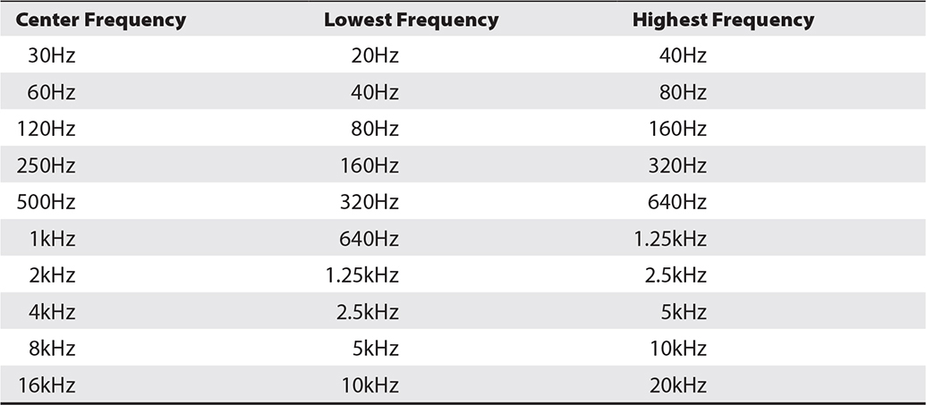
Table 4-1 The Ten Octaves of Human Hearing
In general audio applications, the spectrum of human hearing—20Hz to 20kHz—is divided into 10 bands, each one octave wide. Each band is usually identified by its center frequency. For some purposes, such as in graphic equalizers, the spectrum may be further subdivided into 1/3 octave bands.
Harmonics
Complex audio waveforms often include tones with frequencies that are multiples of each other. If a string is plucked to produce the musical note A, which has a frequency of 220Hz, the string will also produce vibrations at 440Hz (220 × 2), 660Hz (220 × 3), 880Hz (220 × 4), 1,100Hz (220 × 5), 1,320Hz (220 × 6), 1,540Hz (220 × 7), 1,760Hz (220 × 8), etc. These additional vibrations at multiples of the 220Hz note are known as the harmonics of the fundamental 220Hz frequency. The relative proportions of these harmonic frequencies are what help to give a particular note its characteristic sound or timbre, allowing us to recognize the differences between the same note played on a guitar, a mandolin, a ukulele, a balalaika, a double-bass, or a banjo.
The fundamental frequency is also known as the first harmonic frequency. In the previous example, 220Hz is the first harmonic, the second harmonic is 440Hz, the third harmonic is 660Hz, the fourth harmonic is 880Hz, the fifth harmonic is 1,100Hz, the sixth harmonic is 1,320Hz, and so on.
Logarithms
The logarithm (log10 or, more commonly, just log) of a number is how many times the number 10 must be multiplied by itself to get that number. For example, the log of 1,000 is 3, because 1,000 is 10 multiplied by itself three times (10 × 10 × 10), usually shown as 103. Similarly, the log of 100,000,000 is 8 (108), and the log of 0.0001 is –4 (10−4). As you can see in Table 4-2, using the logarithms of numbers enables us to express large ranges of values in a more compact format without the need for all the leading and trailing zeros.

Table 4-2 Examples of Numbers and Their Logarithms
On a standard ruler, each scale mark represents a single unit, wherever it’s located on the ruler. The distance between 3 and 6 on the scale represents a difference of three units, just as the distance between 9 and 12 represents a difference of three units. There is a one-to-one relationship between the units shown and the units represented. This is a linear scale.
However, if we make a ruler with a logarithmic scale, each scale mark on the ruler represents a logarithmic value of 1, which is a 10 times factor, to the next scale mark. If we move to the right, each scale unit represents a number 10 times larger than its predecessor. If we move to the left, each scale represents a number 1/10 of its predecessor. Look at the graph in Figure 4-4. The top row represents a linear scale, and the bottom row represents a logarithmic scale.
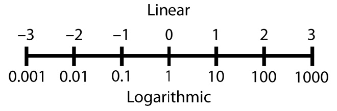
Figure 4-4 Comparing a linear scale and logarithmic scale
Why is this important? Because humans perceive differences between sound pressure levels logarithmically, not linearly, over a range of about 3,000,000:1 between the threshold of hearing and the onset of acoustic pain. Therefore, a base-10 logarithmic scale is used to measure, record, and discuss sound level differences.

NOTE Not only is our perception of sound intensity logarithmic, but so are our other senses. The psychophysical law (or Weber–Fechner law) describes this generalization in psychology. It states that the intensity of a sensation is proportional to the logarithm of the intensity of the stimulus causing it. So, the relationship between our sensations—such as sight, hearing, and touch—and the stimulus is logarithmic.
Decibels
The AV industry frequently uses decibel measurements, so it is important for you to understand what decibels are and how they are used.
The decibel (dB) is a measure of the logarithmic ratio between two quantities of the same physical property such as pressure, power, or voltage. As a logarithmic scale, it is well suited to describing ratios with a potentially very large range of values.
The basic unit, the Bel, was named after telecommunications pioneer Alexander Graham Bell, but the Bel has turned out to be too large for most practical purposes, so the decibel (dB) is the standard unit used (1dB = 0.1Bel).
Bel = log10(quantity1/quantity2)
dB = 10 × log10(quantity1/quantity2)
Decibel Measurements
Decibels are used for quantifying differences in measurements of voltage, distance, power, or sound pressure. They are frequently used to compare a measurement to some already known measurement, known as a reference level. Sound pressure level (SPL) is measured in this way using the threshold of human hearing, a pressure of 20 microPascal (µPA), as the reference level. This is commonly referred to as the 0dB SPL reference level.
The Pascal (Pa) is the international unit for pressure, and 1Pa = 0.00015 pounds per square inch.
We can calculate the difference in decibels between two power levels using the following equation:
dB = 10 × log10(P1/P2)
This would give us the ratio in decibels if we compared one power level in watts (P1) against another power level in watts (P2).
However, where currents or voltages are being compared, because power is related to the square of the voltage or the square of the current (P = V 2 / R or P = I2 × R), the calculation of dB needs to take account that quadratic relationship. The equation:
dB = 20 × log(V1/V2)
will give us the difference in decibels if we compared one voltage (V1) against another voltage (V2).
Similarly, when the property being measured involves a field such as radiated power from a radio transmitter or sound pressure radiating from a source, the field strength is proportional to the square of the distance from the source, requiring decibel calculations to account for this quadratic relationship. For example, this equation:
dB = 20 × log(D1/D2)
would give us the difference in decibels if we compared the sound pressure level at one distance (D1) from the source as compared to the sound pressure level at some other distance (D2) from the source.
Now that you know that you perceive differences in sound levels logarithmically and that you use the decibel for a logarithmic scale, let’s explore further how the decibel is used.
Using the Decibel
Not only can you compare one number against another number of the same type, you can also compare a number against a known reference level. For example, using the 20 log equation, you can compare the difference in decibels between two sound pressure levels. As you learned earlier, you can also compare a sound pressure level measurement in decibels against a known sound pressure reference level in decibels.
For a measured SPL of 85dB to be meaningful, it must have a reference, because decibels are comparisons, not units of absolute quantity. Without a reference, it would be like saying, “It is 10 degrees hotter today than yesterday.” Without knowing yesterday’s temperature, you cannot know today’s temperature because you lack that reference. You need to know what 85dB means relative to something. That 85dB SPL measurement is 85dB of sound pressure referenced to the 0dB SPL threshold of hearing.
Reference levels are also used for other measurements. We commonly use 0dBu (= 775mV) and 0dBV (= 1.0V) to express voltage levels, and 0dBm (= 1mW) for electrical power levels. While –20dBu is a voltage less than 0dBu, it does not mean a negative voltage, but rather a voltage less than 775mV.
In relation to human hearing, the following are some accepted generalities:
• A 1dB change is the smallest perceptible change. Unless they’re listening very carefully, most people will not discern a 1dB change.
• A “just noticeable” change, either louder or softer, requires a 3dB change (such as 85dB SPL to 88dB SPL).
• A 10dB change is required for people to subjectively perceive either a change as twice as loud as before or one-half as loud as before. (For example, a change from 85dB SPL to 95dB SPL is perceived to be twice as loud as before.)
The Inverse Square Law and Sound
As mentioned earlier, sound waves move out and away from the source of generation. Again, envision a rock is thrown into water. The waves of energy move away from the source of molecule disturbance in concentric circles. This occurs as the energy is transferred to nearby molecules. With the rock and water illustration, you see the energy spreading out only on the horizontal plane of the water surface. However, when a sound is generated, the energy is spread spherically in all directions.
Regardless of whether the energy propagates horizontally or spherically, you can follow its spread by using the inverse square law. The inverse square law states that sound energy is inversely proportional to the square of the distance from the source. This occurs because every time the distance doubles from the source of the energy, the energy spreads out and covers four times the area it did before.
For example, if you are five meters from an energy source and then double your distance from the source to 10 meters, the energy must now cover an area four times larger than it did at the 5m distance (area = 4πr2). In other words, for every doubling of the distance, there is a fourfold increase in the surface area of the sphere, reducing the amount of energy at any point on the sphere to one-quarter of its previous level.
Simply put, sound pressure is reduced by 6dB every time the distance from the source is doubled. Conversely, the sound pressure increases by 6dB when the distance from the source is reduced by one-half. This is often referred to as the 6dB per doubling rule.
NOTE The inverse square law doesn’t apply only to sound. It applies to everything that radiates outward from a source, such as light, radio waves, gravity, magnetism, and the electric field.
In practice, a true reduction by 6dB for every doubling of distance occurs only in a near-field (within a few wavelengths of the source) or free-field (where there are no reflections of the source) environment. These terms describe the space around a sound source that does not include energy reflected back by boundaries, such as walls, ceilings, and floors.
Digital Audio
Although most audio in AV systems begins and ends its journey as soundwaves, for the majority of its path through the system it travels as an electronic signal that may be either an analog waveform corresponding to the amplitude and frequencies of soundwaves or a digital representation of that analog waveform.
As discussed in Chapter 3, analog waveforms are subject to signal degradation and system noise during their transmission through an audio system, while a digital representation of that waveform remains immune to both system noise and degradation.
Digitizing Analog Audio
Specialized circuitry is employed to sample an analog audio waveform at regular intervals and convert the voltage at each sample point into a number representing the amplitude of the waveform at the time of the sample. The number of samples taken (the sample rate) and the accuracy of the digital representation of the amplitude (the bit depth) are the factors governing the accuracy of the digital representation of the original analog signal. The higher the sample rate and the greater the bit depth, the more accurate the digital representation and the more bandwidth required to transmit the signal.
The formula to calculate the bandwidth required for a digital audio signal is the following:
Bandwidth = Sample Rate × Bit Depth × Number of Channels
where:
Bandwidth is measured in bits per second.
Sample rate is measured in samples per second (Hz).
Bit depth is measured in bits per sample.
Sample Rate
As mentioned in Chapter 3, the sample rate for the audio compact disc was set at 44.1kHz in the “Red Book” compact disc–digital audio (CD-DA) specification jointly published by Sony and Philips in 1980. The majority of this specification was later adopted as an International Electrotechnical Commission (IEC) standard. This sample rate was established as a trade-off between the limitations of the optical disc technologies of the time and the minimum requirement of the Nyquist–Shannon sampling theorem for samples to be taken at twice the highest frequency that would be sampled, in this case approximately 20kHz. This 44.1kHz sample rate has served well in the field of commercial audio replay ever since, despite its now-acknowledged shortcomings at capturing some subtle harmonic overtones, a problem not generally noticeable in most commercial or domestic listening environments.
As the technological limitations of signal sampling rates have progressively been overcome, professional audio applications such as recording, mix-down, post-production, and high-fidelity live production tend to use higher sample rates to capture more of the overtones and subtle waveform variations in the source signal. These systems generally operate at sample rates of 48kHz (for a maximum frequency of 24kHz), 96kHz (for a maximum frequency of 48kHz), or 192kHz (for a maximum frequency of 96kHz).
Bit Depth
The bit depth of a digital audio signal defines the number of different signal levels that can be encoded as discrete numbers in the digitization process. In the case of CD audio, the bit depth was set at 16 bits per sample, allowing the digitizer to differentiate between 216 (65,535) discrete sound levels, or a dynamic range of approximately 96dB, which covers most of the range of human hearing. However, as all digitization requires the rounding of an infinitely variable analog signal to one of a fixed range of digital levels, some quantization errors will occur. The level of quantization noise in CD audio is low enough to be overlooked in most domestic and commercial listening environments, but it is detectable under good listening conditions and becomes more prominent as multiple digital audio signals are mixed together and processed.
To reduce quantization errors, bit depths of 24 bits (~144dB dynamic range) and 32 bits (~192dB dynamic range) are employed in many professional recording, mixdown, post-production, and high-fidelity live performance applications. Digitizing at higher bit depths may reduce quantization artifacts during processing, but it does not eliminate them when the signal is finally downsampled to a 16-bit depth for replay on CD-quality systems.
Digital Audio Compression
Most professional audio-visual applications that require high-quality audio, transmit and store digital audio in an uncompressed form, as this eliminates the processing overhead and possible signal latency associated with encoding and decoding the signal.
Common uncompressed audio data formats include pulse code modulation (PCM) formats such as CD audio, Audio Interchange File Format (AIFF), Motion Picture Experts Group (MPEG) audio, HDMI audio, AES3 also known as Audio Engineering Society/European Broadcasting Union (AES/EBU), and Waveform Audio File (WAV).
Digital audio compression may be required where there are limitations to the bandwidth available to transmit an audio stream or where there is limited space available to store the stream for later replay. There are two types of digital audio compression, lossless and lossy.
Lossless Audio Compression
Lossless compression retains all the audio quality of the original digitized waveform, employing mathematical processes to reduce the size of the digital audio stream by between 50 and 70 percent. The lossless compression and decompression processes require significant processing power, which may introduce noticeable latency if used in live production. It is, however, suitable for use in high-quality recording and remote streaming applications.
Common open source lossless compression formats include free lossless audio codec (FLAC), the two-file WavPack system, Monkey’s Audio, and Apple lossless (ALAC or ALE).
Lossy Audio Compression
Lossy audio compression enables significant file and stream size reduction, with the trade-off being a reduction in the accuracy of the reproduction of the original digital audio signal. The impact of the data loss is minimized by the compression algorithms being designed on the basis of psychoacoustic analysis to discard the elements of the original waveform that are least perceivable by the listener. Target listening conditions, such as high ambient noise environments in motor vehicles or public places, also allow the compression process to reduce the dynamic range of the compressed signal without a significant impact on the listener.
Lossy audio compression may be suitable for use where high-quality audio is not required. This includes high ambient noise environments, low-level background music systems, voice-only announcement systems, and applications where the replay system is not capable of full-range audio reproduction.
Commonly used lossy compression formats include MPEG-2 Audio Layer III (MP3), the most popular, and Advanced Audio Coding (AAC). Even the highest-quality 320kbps MP3 stream represents an approximately 75 percent reduction in bandwidth from CD audio’s 1.4Mbps. The more commonly used 160kbps MP3 stream represents a 90 percent bandwidth reduction from uncompressed CD-quality audio.
Digital Audio Network Protocols
Digital audio signals can be transmitted from one source to multiple endpoints over standard networks. Over the years, many proprietary protocols such as CobraNet and EtherSound for transporting audio directly over Ethernet (but not TCP/IP) were developed, and some were fairly widely adopted. However, the introduction of the AES67 interoperability standard has simplified the choice of equipment and protocols used for networked audio. The following are among the more popular network audio protocols:
• Audio Video Bridging (AVB) AVB is an IEEE standard protocol that transports uncompressed video and up to 200 channels of 48kHz/24-bit audio in real time, plus embedded control and monitoring, using Ethernet frames. It requires specialized, and relatively costly, AVB-enabled switches and network components but does not require separate network infrastructure or dedicated bandwidth.
• Dante Dante operates over TCP/IP networks and is not dependent on an underlying Ethernet network. Over Gigabit Ethernet (1Gbps), Dante transports up to 1,024 channels of 48kHz/24-bit audio; 512 channels at 96kHz/24 bit; or HDMI video including eight channels of audio. Over 100Mbps Ethernet, it can transport up to 96 channels of 48kHz/24-bit audio, or 48 channels at 96kHz/24 bit. Dante is fully routable over IP networks using standard Ethernet switches, routers, and other components. It requires no separate infrastructure.
Audio Data Streaming
There are two major architectures used for streaming AV data across networks, unicast and multicast.
• Unicast streaming Unicast streaming is a one-to-one connection between the streaming server sending out the AV data and client devices listening to the stream. Each client has a direct relationship with the server. The client sends a request to the server, and the server sends the client a stream in response. Since the server is sending out a separate stream for each client, each additional client takes up more bandwidth. Streaming media to three clients at 100kbps actually uses 300kbps of bandwidth. Unicast streams may be sent between networks, but there will always be some buffering.
• Multicast streaming Multicast streaming is a one-to-many transmission: one server sends out a single stream that can then be accessed by multiple clients. Class D IP addresses (224.0.0.0 to 239.255.255.255) are set aside for multicast transmissions. In multicast streaming:
• A server sends the stream to a designated Class D IP address, called the host address.
• The clients subscribe to the host address.
• Routers send the stream to all clients subscribing to the host address.
Multicast streams can only be sent across LANs or private networks; they cannot be sent over the open Internet.
Acoustics
Acoustics is a branch of science that focuses on the qualities and characteristics of sound waves. As you might expect, the study of acoustics covers many topics. It is more than simply hanging some fabrics on a wall to solve an “acoustical problem.”
The study of acoustics includes the following:
• How sound is generated
• How sound energy moves through air and other media (such as concrete, steel, and water)
• How dimensions and shapes of surfaces affect the way sound behaves in an environment
• How sound energy can be prevented from leaving or entering a space through partitions or vibrations
• What happens to sound energy when it encounters a boundary (a change of materials)
• Your perception of a sound as processed by your ear and brain
Sound energy moves out and away from a source in all directions. Unless the sound is generated in a completely free space, the energy will, at some point, encounter a boundary or surface. If you’re outdoors, the boundaries may be only the ground or nearby buildings. But indoors, there can be many boundaries and surfaces. Along with the walls, ceilings, and floors, furniture and people also affect what happens to sound energy in an environment.
So, what happens to the energy produced by a sound-reinforcement system or other source of generated sound? The law of conservation of energy tells us that total energy neither increases nor decreases in any process. Energy can be transformed from one form to another—and transferred from one body to another—but the total amount of energy remains constant. This means that when the radiating sound energy encounters a surface or room boundary, some combination of three things will occur.
• The sound is reflected. As the sound energy moves away from the source, some of it will be reflected back off various surfaces. The reflections can be specular (direct) or diffused (scattered). Either way, the total amount of energy remains in the space.
• The sound is absorbed, either in the air (not much of an issue except in extremely large spaces) or by the materials in the space (sound energy is converted into low-level heat).
• The sound is transmitted. In other words, the energy actually passes from one space to another through a partition or other barrier.
Reflected Sound Energy
There are two types of sound reflections:
• Direct reflection This is also known as a specular or hard reflection. This type of reflection is mirror-like; most of the energy is reflected back, coherently, in a single direction from each point on the surface. As with light, the direction of the angle of reflected sound energy is determined by the incoming angle, as the angle of incidence is equal to the angle of reflection.
• Diffuse reflection This type of reflection scatters the energy back in many directions. This is similar to the properties of a diffusion-type projection screen.
Whether the energy is reflected in a specular or diffuse fashion depends on how smooth a surface is, relative to the wavelength. Because we’re dealing with a range of wavelengths, the transition between specular and diffuse reflection is not immediate, and neither is how much energy is reflected, absorbed, or transmitted. Some wavelengths will undergo specular reflection, some will undergo diffuse reflection, while others will act somewhere in between. Their behavior is determined by the size, the nature of the material, and the mass of the boundaries in a space.
In every situation involving boundaries or surfaces, you will always have some direct sound (sound that arrives at the listener position in a direct, straight line) and some reflected sound (sound that takes an indirect path from the source to the listener).
Reflected energy arrives later in time than direct sound because the shortest path between two points is a straight (direct) line. Taking other paths requires traveling a longer distance and requires more time. Thus, reflected sound will always arrive later than direct sound. Reflections can be defined as early or late. A late reflection is called an echo.
Reverberation
When a venue has many hard, reflective surfaces, the energy level of each sound reflection can remain quite high. As energy reflects off more surfaces around a room, the listener begins to receive reflected energy from all directions. When the energy level remains high and the reflections become dense in relation to one another, it is called reverberation. Reverberation simply describes numerous, persistent reflections.
True reverberation is a phenomenon seen in larger spaces with many hard, reflective surfaces. While a typical conference room may have troublesome reflections, it is unlikely to exhibit true reverberation.
Absorption
The materials used in the construction and finish of a venue (walls, ceiling, floor, furniture, curtains, windows, seating, etc.), as well as people themselves, play a part in the amount of sound energy absorbed.
One type of absorber you may be familiar with is the porous absorber panel. As the displaced air molecules pass through a porous absorber, the friction between the molecules and the material of the absorber slow down the molecules. Typical porous absorbers include carpets, acoustic tiles, acoustical foams, curtains, upholstered furniture, and people (clothing). Figure 4-5 shows an example of using acoustic tiles.
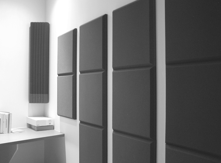
Figure 4-5 An acoustic treatment using absorbent tiles
Though acoustically absorptive material may be applied in a room, effective absorption will occur only over a limited frequency range. Energy above or below the effective frequency band of the absorption will be either reflected or transmitted.
Transmission
Sound energy that is not reflected or absorbed will be transmitted into another space through partitions (walls, windows, floors, and ceilings) or as structure-borne vibrations. The ability of a partition to transmit or reflect sound energy is limited by factors such as the weight of the partition (mass), stiffness of the partition material, air gaps, design of the partition, and internal structure of the partition.
Ambient Noise
Noise is generally defined as anything other than the desired signal. While an electronic sound system inherently generates noise through its electronic components, rooms are also characterized by noise.
Anything heard in a room other than the desired signal from a sound-reinforcement system is considered background or ambient noise. This can include noise from equipment fans; office equipment; telephones ringing; heating, ventilation, and air conditioning (HVAC) systems; and people in the room. Noise can intrude from outside the room as well, through partitions or windows. Outside sources may include vehicular traffic, weather sounds, adjoining corridors, or structure-borne vibrations.
Ideally, because excessive noise levels interfere with the message being communicated, an acoustician, AV consultant, or designer should specify background noise level limits appropriate to the type of room and its purpose. In practice, the criteria and limits for background noise levels for a gymnasium will be much different from those for a conference room. With such limits determined, parts of the project—the HVAC system, partitions, and necessary acoustical treatments, for example—may be designed and applied so that the background noise level criteria are not exceeded.
A room’s acoustical properties (its reflections and types and amount of transmission allowed) and background noise levels are significant contributors to a sound system’s overall effectiveness.
Sound Capture
You have read about the basics of sound propagation, sound wave frequency and wavelength, harmonics, the decibel, and the sound environment. How do these basics apply to the AV industry? They help you understand the electrical pathway used to amplify sound.
In its most basic form, the complete audio-signal path takes acoustic energy and converts it into electrical energy so it can be routed, processed, further amplified, and converted back into acoustic energy, as follows:
1. The sound source creates sound wave vibrations in the air.
2. A microphone picks up the vibrations.
3. The microphone converts the vibrations into an electrical signal.
4. The electrical signal is processed.
5. The signal ends up in an output device (such as an earphone or a loudspeaker).
6. The output device converts the electrical signal back into sound waves.
This conversion of energy from one form to another is called transduction. A microphone is a transducer—it converts acoustic energy into electrical energy. A loudspeaker is also a transducer—it converts the electrical energy into acoustic energy. This means you can have transducers on either end of an electrical audio path.
Microphones
Understanding a microphone’s construction and its intended usage, as well as its directional, sensitivity, frequency response, and impedance characteristics, will help you select the appropriate microphone for each situation.
Microphones come in a variety of types, sizes, and construction. Carbon microphones were once widely used in telephones. There are also ceramic, fiber-optic, laser, piezoelectric, ribbon, moving coil, microelectromechanical systems (MEMS), condenser, and electret microphones, each with its own application and characteristics.
Dynamic Microphones
In a dynamic microphone (mic), you will find a coil of wire (a conductor) attached to a diaphragm and placed in a permanent magnetic field. Sound pressure waves cause the diaphragm to move back and forth, thus moving the coil of wire attached to it.
As the diaphragm-and-coil assembly moves, it cuts across the magnetic lines of flux of the magnetic field, inducing a voltage into the coil of wire. The voltage induced into the coil is proportional to the sound pressure and produces an electrical audio signal. The strength of this signal is very small and is called a mic-level signal.
Dynamic microphones are used in many situations because they are economical and durable, and they will handle high sound pressure levels. Dynamic microphones are very versatile because they do not require a power source.
Condenser Microphones
In the study of electricity, you will find that if you have two oppositely charged (polarized) conductors separated by an insulator, an electric field exists between the two conductors. The amount of potential charge (voltage) that is stored between the conductors will change depending on the distance between the conductors, the surface area of the conductors, and the dielectric strength of the insulating material between the two conductors. An electronic component that uses this principle is called a capacitor.
A condenser microphone (see Figure 4-6 for an example) contains a conductive diaphragm and a conductive backplate. Air is used as the insulator to separate the diaphragm and backplate. Electrical power is required to polarize, or apply, the positive and negative charges to create the electric field between the diaphragm and backplate.
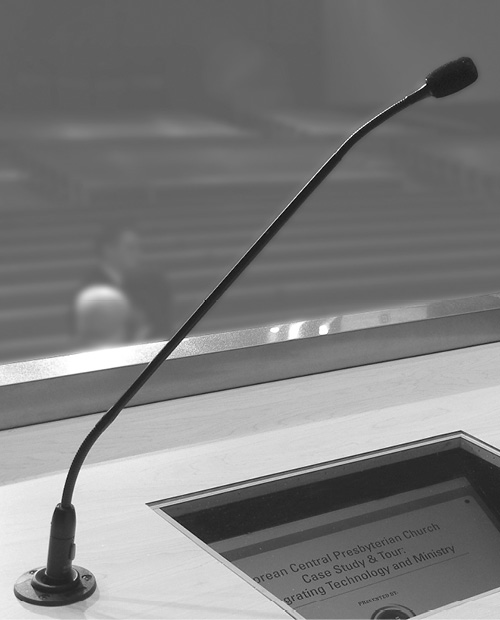
Figure 4-6 A condenser microphone on a lectern
Sound pressure waves cause the diaphragm to move back and forth, subsequently changing the distance (spacing) between the diaphragm and backplate. As the distance changes, the amount of charge, or capacitance, stored between the diaphragm and backplate changes. This change in capacitance produces an electrical signal.
The strength of the signal from a condenser microphone is not as strong as the mic-level signal from a typical dynamic microphone. To increase the signal, a condenser microphone includes a preamplifier, powered by the same power supply used to charge the plates in the microphone. This preamplifier amplifies the signal in the condenser microphone to a mic-level signal but is not to be confused with a microphone preamplifier found in a mixing console.
The power supply to charge the capacitor elements and drive the preamplifier may be a battery included in the microphone body, an external mains-powered supply device, or come from an external phantom power supply system.
As the diaphragm used in a condenser microphone is usually lower in mass than other microphone types, the condenser microphone tends to be more sensitive than other types and responds better to higher frequencies, with a wider overall frequency response.
Electret Microphones
An electret microphone is a type of condenser microphone. The electret microphone gets its name from the prepolarized material, or the electret, applied to the microphone’s diaphragm or backplate.
The electret provides a permanent, fixed charge for one side of the capacitor configuration. This permanent charge eliminates the need for the higher voltage required for powering the typical condenser microphone. This allows the electret microphone to be powered using small batteries, or normal phantom power. Electret microphones are physically small, lending themselves to a variety of uses and quality levels.
MEMS Microphones
A microelectromechanical system (MEMS) microphone is a member of a group of mechanical devices that are built directly onto silicon chips using the same deposition and etching processes used to construct microprocessors and memory systems. They are minute mechanical devices that can be directly integrated with the pure electronic circuitry of the chip. The best known of these in the AV world are the digital micromirror devices (DMD) used for light switching in DLP projectors. Many other MEMS devices are in wide commercial use as accelerometers, air pressure sensors, gyroscopes, optical switches, ink-jet pumps, and even microphones.
Microphones built using MEMS technologies are generally variations on either condenser microphones or piezo-electric (electrical signals produced by the mechanical movement of a crystal) microphones. Although their tiny size means that MEMS microphones are not particularly sensitive, especially at bass frequencies, the huge advantage of MEMS microphones is that they can be constructed in arrays to increase sensitivity and that they can be placed on the same chip as the amplifiers and signal processors that manage both gain and frequency compensation. The on-chip processing can include analog-to-digital conversion, resulting in a microphone with a direct digital output. In addition to dedicated MEMS microphones, smartphones, smart speakers, tablet computers, virtual reality headsets, and wearable devices can incorporate chips that include a range of MEMS devices, including microphones, accelerometers, and gyroscopes, and all of their associated processing circuitry.
Defining Phantom Power
Phantom power is the remote power used to power a range of audio devices including condenser microphones. It typically ranges from 12V to 48V DC, with 48V being the most common. Positive voltage is applied equally to the two signal conductors of a balanced audio circuit, with the power circuit being completed by current returning through the cable’s shield. Because the voltage is applied equally on both signal conductors, it has no impact on the audio signal being carried and does not cause damage to dynamic microphones.
Phantom power is frequently available from audio mixers. It may be switched on or off at each individual microphone input, enabled for groups of microphone channels, or enabled from a single switch on the audio mixer that makes phantom power available on all the microphone inputs at once. If phantom power is not available from an audio mixer, a separate phantom power supply that sits in line with the microphone may be used.
Microphone Physical Design and Placement
Whether dynamic, condenser, electret, or otherwise, microphones come in an assortment of configurations to meet a variety of uses. The following are some common microphone configurations:
• Handheld This type is used mainly for speech or singing. Because it is constantly moved around, a handheld microphone includes internal shock mounting to reduce handling noise.
• Surface mount or boundary This type of microphone is designed to be mounted directly against a hard boundary or surface, such as a conference table, a stage floor, a wall, or sometimes a ceiling. The acoustically reflective properties of the mounting surface affect the microphone’s performance. Mounting a microphone on the ceiling typically yields the poorest performance, because the sound source is much farther away from the intended source (for example, conference participants) and much closer to other noise sources, such as ceiling-mounted projectors and HVAC diffusers.
• Gooseneck Used most often on lecterns and sometimes conference tables, this type of microphone is attached to a flexible or bendable stem. The stem comes in varying lengths. Shock mounts are available to isolate the microphone from table or lectern vibrations.
• Shotgun Named for its physical shape and long and narrow polar pattern, this type of microphone is most often used in film, television, and field-production work. You can attach a shotgun microphone to a long boom pole (fishpole), to a studio boom used by a boom operator, or to the top of a camera.
• Instrument This family of microphones is designed to pick up the sounds of musical instruments, either directly from acoustic instruments or from the loudspeaker cabinet of an amplified instrument. This type of microphone is usually either a condenser or a dynamic device, depending on the loudness, dynamic range and frequencies to be picked up from the instrument. Some specialized instrument transducers use direct mechanical or magnetic pickups.
• Lavalier and headmic These microphones are worn by a user, often in television and theater productions. A lavalier (also called a lav or lapel mic) is most often attached directly to clothing, such as a necktie or lapel. In the case of a headmic, the microphone is attached to a small, thin boom and fitted around the ear. As size, appearance, and color are critical, lavaliers and headmics are most often electret microphones.
• Beamforming array Beamforming arrays have multiple microphone elements, usually condenser microphone capsules or MEMS microphones. These elements are configured in arrays of varying shapes and linked together through a digital signal processing system to form narrow beam patterns that can be electronically steered to pick up the desired sounds while rejecting ambient noise. Array microphones can be placed in convenient locations such as on a wall, on a tabletop, or on the ceiling, as shown in Figure 4-7. Microphone array devices are primarily used in meeting rooms, in conferencing spaces, on desks, and on lecterns.

Figure 4-7 A ceiling-mounted multimicrophone array used for meeting rooms (courtesy Sennheiser)
Microphone Polar Patterns
One of the characteristics to look for when selecting a microphone is its polar pattern. The polar pattern describes the microphone’s directional capabilities—in other words, the microphone’s ability to pick up the desired sound in a certain direction while rejecting unwanted sounds from other directions.
Polar patterns are defined by the directions from which the microphone is optimally sensitive. These polar patterns help you determine which microphone type you should use for a given purpose. There will be occasions when you want a microphone to pick up sound from all directions (like an interview), and there will be occasions when you do not want to pick up sounds from sources surrounding the microphone (like people talking or someone rustling papers). The polar pattern is also known as the pickup pattern or a microphone’s directionality.
As a microphone rejects sounds from undesired directions, it also helps to reduce potential feedback through the sound system. The following polar patterns are available:
• Omnidirectional Sound pickup is uniform in all directions.
• Cardioid (unidirectional) Pickup is primarily from the front of the microphone (one direction) in a cardioid pattern. It rejects sounds coming from the side, but the most rejection is at the rear of the microphone. The term cardioid refers to the heart-shaped polar patterns.
• Hypercardioid A variant of the cardioid, this type is more directional than the regular cardioid because it rejects more sound from the side. The trade-off is that some sound will be picked up directly at the rear of the microphone.
• Supercardioid This type provides better directionality than the hypercardioid, as its rejection from the side is better. It also has more rear pickup than the hypercardioid.
• Bidirectional Pickup is equal in opposite directions, with little or no pickup from the sides. This is sometimes also referred to as a figure-eight pattern because of the shape of its polar patterns.
Figure 4-8 shows various types of microphone polar patterns.

Figure 4-8 Microphone polar patterns: omnidirectional, cardioid, supercardioid, and bidirectional
Microphone Sensitivity
One performance criterion that characterizes a microphone is its sensitivity specification. This defines its electrical output signal level given a reference sound input level. Put another way, sensitivity defines how efficiently a microphone transduces (converts) acoustic energy into electrical energy.
If you expose two different types of microphones to an identical sound pressure level, a more sensitive microphone provides a higher electrical output than a less sensitive microphone. Generally speaking, condenser microphones have a greater sensitivity than dynamic microphones.
Does this mean that a lower sensitivity microphone is of lesser quality? Not at all. Microphones are designed and chosen for specific uses. For example, a professional singer typically uses a microphone up close, which can produce a very high sound pressure level. In contrast, a presenter speaking behind a lectern and a foot or two away from the microphone produces a much lower sound pressure level. For the singer, a dynamic microphone may be the best choice, as it will typically handle the higher sound pressure levels without distortion, while still providing more than adequate electrical output. The presenter, using a microphone farther away than a singer’s, would certainly benefit from a more sensitive microphone.
Here is an example of a sensitivity specification:
−54.5dBV/Pa
A pressure of 1Pa is the equivalent of 94dB SPL. In this example, if we were to put 94dB SPL into the microphone, we would realize a –54.5dBV electrical output signal.
Although most manufacturers use 94dB SPL as the reference input level, you may also find 74dB SPL (0.1Pa) used as the reference level. Using a different input reference level would obviously produce a different output level.
Microphone Frequency Response
Another important measure of a microphone’s performance is its frequency response. This defines the microphone’s electrical output level over the audible frequency spectrum, which in turn helps determine how an individual microphone sounds.
A microphone’s frequency response gives the range of frequencies, from lowest to highest, that the microphone can transduce. It is often represented as a plot on a two-dimensional graph of electrical output versus frequency, as shown in Figure 4-9. A graphical representation of the microphone’s directional and frequency response characteristics is called a polar plot.

Figure 4-9 A frequency response chart for a microphone
With directional microphones, the overall frequency response will be best on-axis (directly into the front of the microphone). As you move off-axis with a directional microphone, not only will the sound be reduced, but the frequency response will also change.
Microphone Impedance
For a microphone to be of any use, you must plug it into something. How do you know if the microphone is compatible with the device you’re plugging it into?
Another microphone specification you must consider is its output impedance. Impedance is the opposition to the flow of electrons in an alternating current (AC) circuit. (Audio signals are AC circuits.) Resistance is the opposition to current flow in a direct current (one-way) DC circuit. Both impedance and resistance are measured in ohms (Ω).
In the early days of the telephone and vacuum tubes, it was necessary to match output impedance with input impedance for maximum power transfer. Modern audio systems use a maximum voltage transfer instead. To accomplish this, a device’s output impedance should be one-tenth or less than the input impedance the device is being plugged into. For example, a professional microphone’s output impedance specification should be 200Ω or less. An input to be used with a professional microphone will have an input impedance of 2kΩ or more.
Microphones can fall into two categories, based on output impedance:
• Low impedance, which is 200Ω or less (some as high as 600Ω)
• High impedance, which is more than 25kΩ
Professional microphones are low-impedance microphones. Low-impedance microphones are less susceptible to noise and allow for much longer cable runs than high-impedance microphones.
Wireless Microphones
Sometimes called radio mics, wireless microphones use radio frequency (RF) transmission in place of a microphone cable to link to the rest of the audio system. Some wireless systems use infrared (IR) transmission.
For a handheld microphone, a standard microphone casing is often integrated onto the top of a transmitter, and the microphone casing and transmitter are finished as one unit. At other times, a small plug-style transmitter is plugged into the output connecter of a regular handheld microphone.
For hands-free applications, a lavalier or headmic microphone is plugged into a bodypack-style transmitter, as shown in Figure 4-10. The bodypack transmitter is then clipped onto a belt or placed in a pocket or pouch. At the other end of the RF transmission is a receiver tuned to the transmitter’s specific frequency.
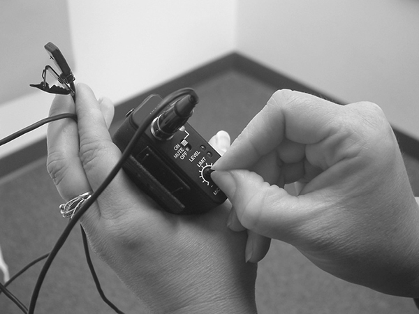
Figure 4-10 A wireless lavalier microphone and bodypack
Most RF wireless microphones allow you to select from a range of available frequencies to avoid interference from outside sources and cross-talk or intermodulation distortion from other wireless devices that may be in use. Some RF systems employ spread-spectrum frequency-hopping technologies to minimize cross-talk between transmitters and eliminate eavesdropping. Digital wireless links are increasingly being used to ensure privacy and eliminate RF signal noise.
Even the best available wireless microphone link is less reliable and less noise immune than a standard microphone cable.
Spectrum Management
The coordination of wireless frequencies allocated to wireless microphone systems, wireless in-ear monitor systems, communications systems, and the multitude of other wireless technologies involved in audiovisual installations and operations is critical. A full-spectrum frequency allocation plan is an important component of any audiovisual installation or production. The plan must take into account local frequency allocation regulations, as described in the “Allocation of Radio Frequencies” section in Chapter 10.
Microphone Cables and Connectors
Microphones and other input devices are connected to audio mixers with a cable and a connector. Professional microphone cables use shielded twisted-pair cable, which contains the following:
• A pair of small-gauge, insulated, multistranded, copper wires (conductors) twisted together to provide common-mode noise rejection
• An aluminum foil or a braided copper shield that encloses the twisted conductors
• A protective insulated jacket that encloses the twisted pair and the shield
Typically, the ends of the shielded twisted-pair cable are terminated with an industry-standard three-pin XLR connector, with the socket (female connector) at the microphone end and the plug (male connector) at the processing end.
When multiple audio circuits are required between the same points, such as between a presentation point and the mixing console, multicore twisted-pair cables (often called snake cables) are used. Audio multicore cables may be terminated in individual XLR plugs and sockets for each microphone circuit, multipin connectors incorporating all circuits, or terminated in an outlet box incorporating panel-mounted connectors for each circuit.
Audio Signal Levels
Now that you’ve learned how to select the proper microphone and connect it, where do you go from here? First, let’s go over some terminology that relates to audio signals.
• Mic level A microphone, regardless of type, produces a low-level signal level that unsurprisingly is known as mic level. Mic level is only a few millivolts (mV).
• Microphone preamplifier As mic level is a fairly weak signal and subject to interference and system noise, it must be amplified to a more robust line level signal through a microphone preamplifier circuit (widely known as a preamp) before further processing. Preamps are usually incorporated into the microphone input channels of audio processing equipment, although separate mic preamp devices are available.
• Line level, professional Line level in a professional audio system is in the vicinity of 1V. Voltage measurements are often referenced to a 600Ω impedance circuit at 1kHz. Line level is where all signal routing and processing is performed.
• Line level, consumer Line level in consumer devices is lower than line level in a professional environment, being just 316mV. Voltage measurements are often referenced to 10kΩ impedance circuit at 1kHz. Consumer line level can often be identified by its use of 3.5mm (1/8in) stereo jack plugs or RCA (phono) connectors.
• Loudspeaker level Once you have routed and processed the signal, it is sent to the power amplifier for final signal amplification up to loudspeaker level. The loudspeaker takes that amplified electrical signal and transduces the electrical energy into acoustical energy. Loudspeaker feed circuits for large venue systems can be tens of amps at tens of volts.
Signal Level Compatibility
As you begin to connect your system, you need to make sure the components of your system are compatible with each other. For example, while you could plug a microphone directly into the input of a power amplifier, you would not get much sound level. The mic-level signal isn’t strong enough by itself. You also would not want to connect the output of a power amplifier to a device expecting either a mic or line level—you would almost certainly damage components.
What about plugging your microphone directly into the back of an active loudspeaker? Some companies manufacture active or powered loudspeakers, which are all-in-one devices meant to simplify setup and provide for easy portability. In the case of a powered loudspeaker, all of the signal requirements listed earlier are built into the loudspeaker. If the powered loudspeaker has microphone inputs, it will have microphone preamplifiers, and any internal processing will be done at the line level. It will also have the power amplifier built in to drive the loudspeaker.
Signal Level Adjustments
When working with signal levels, you may need to make changes to provide a higher voltage signal or to avoid the signal distortion that results from too much signal voltage.
The following terms are used in association with signal level adjustment:
• If you increase the signal level, it is called adding gain, which refers to the amount of amplification applied to the signal.
• If you decrease the signal level, it is called attenuation.
• Adjustments you make to signal levels are called gain adjustments.
• Gain control refers to the general ability to make adjustments to the signal levels.
• If you apply neither gain nor attenuation to a signal, it is called unity gain. Unity gain means that the signal is passing through the audio system without any changes to its level.
Audio Devices
Now that we’ve reviewed the basics of capturing sound, we’ll look at the devices used to process the audio signal. These include a wide range of equipment, from equalizers to power amplifiers.
Audio Mixers
In its most basic form, an audio system has a sound source at one end and a destination for that sound at the other. In almost all situations, there is more than one source.
Audio technicians deal with multiple and varied sources of sound. The sources could be several vocalists with instruments at a concert; playback devices such as CD, DVD, and MP3 players or media servers; multiple participants in a conference; or several actors in a theater performance. All of these signals come together in the audio mixer.
All audio mixers serve the same purpose: to combine, control, route, and possibly process audio signals from a number of inputs to a number of outputs. Usually, the number of inputs will be larger than the number of outputs.
Audio mixers are often identified by the number of available inputs and outputs. For example, an 8-by-2 mixer would have eight inputs and two outputs. Each incoming mic- or line-level signal goes into its own channel. Many mixers provide individual channel equalization adjustments, as well as multiple signal-routing capabilities, via main or auxiliary buses.
An audio mixer is often also known a mixing console, an audio console, or a mixing desk.
Regardless of the size and complexity, any mixer that accepts mic-level inputs will have microphone preamps. Once the mic level is amplified to line level by the preamp, it can be processed by the rest of the mixer.
Between the inputs and outputs, the typical audio mixer provides multiple gain stages for making adjustments. These adjustments allow the console operator to balance or blend the audio sources together to create the appropriate sound balance for the listening audience.
Some audio mixers will open and close microphone channels automatically, like an on/off switch. These are called gated automatic mixers. Others will turn up microphone channels that are in use and attenuate (or mute) the microphone channels not in use, like a volume knob. These are called gain-sharing automatic mixers. The channels set for automatic mixing should be used only for speech. Other sound sources, such as music, should not be set for automatic mixing. Most applications, especially music, require live operator intervention to achieve an acceptable sound mix.
NOTE Automatic mixers should not be confused with automated mixers, which are automated by computer and store presets, control settings, and various mixing moves.
Audio Processors
Numerous types of processors can refine audio signals. The type you need is determined by intended use and listening environment. Some common processors include limiters, compressors, expanders, gates, and filters.
Compressors, limiters, and expanders are dynamic processors. They either decrease or increase the overall dynamic range of the signal. The term dynamic range refers to the difference between the loudest and quietest levels of a signal. A signal level that varies greatly between the loudest and quietest parts is said to have a wide dynamic range. Compressors and limiters operate on the same principles but have quite different uses.
Compressors have the following characteristics:
• They reduce the level of all signals above an adjustable threshold. In other words, they keep loud signals from being too loud.
• The amount of reduction above the threshold is determined by an adjustable ratio.
• The reduction reduces the variation between highest and lowest signal levels, resulting in a compressed (smaller) dynamic range.
• They can be used to prevent signal distortion.
Extreme compression is called limiting.
Limiters are described as follows:
• They limit the level of all signals above an adjustable threshold. In other words, they prevent high-amplitude signals from getting through.
• Limiting is used to prevent damage to components such as loudspeakers.
• They are triggered by peaks or spikes in the audio signal (like a dropped microphone), and they react quickly to cut them off before they exceed a certain point.
• The amount of limiting above the threshold is determined by a more aggressive ratio than a compressor reduction ratio.
• The reduction limits the variation between highest and lowest signal levels, resulting in a limited dynamic range.
Figure 4-11 shows the effects on a signal after using a limiter.

Figure 4-11 The effects on a signal after using a limiter
Expanders, which are more properly thought of as downward expanders, are described as follows:
• They reduce the level of all signals below an adjustable threshold.
• The amount of reduction below the threshold is determined by an adjustable ratio.
• The signal-level reduction increases the variation between highest and lowest signal levels, resulting in an increased dynamic range.
• They are used for reducing unwanted background noise.
Gates have the following characteristics:
• They can be thought of as an extreme downward expander.
• They mute the level of all signals below an adjustable threshold.
• Signal levels must exceed the threshold setting before they are allowed to pass.
• They can be used to automatically turn off unused microphones.
Figure 4-12 shows the effects of applying a gate.
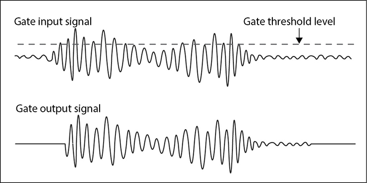
Figure 4-12 Impact of applying a gate on input signal amplitudes
Filters are described as follows:
• They filter (attenuate) certain frequencies from a signal.
• A notch filter “notches out” (attenuates) a specific narrow-frequency range.
• Low-pass filters pass the low-frequency content of a signal and attenuate the high-frequency range.
• High-pass filters pass the high-frequency content of the signal and attenuate the low-frequency range.
Figure 4-13 shows low-pass and high-pass filters at work.

Figure 4-13 The effects of high-pass and low-pass filters
Equalizers
Equalizers (EQs) are frequency controls that allow you to boost (add gain) or cut (attenuate) a specific range of frequencies. The simplest equalizers are the broad bass and treble tone controls found on your home stereo or surround-sound receiver. The equalizer found on the input channel of a basic audio mixer may provide simple high-, mid-, and low-frequency controls.
In the audio-visual world, two types of sound-system equalizers are common.
• Graphic equalizer A common graphic equalizer is the 1/3-octave equalizer, which provides 30 or 31 slider adjustments corresponding to specific fixed frequencies with fixed bandwidths. The frequencies are centered at every one-third of an octave. The numerous adjustment points allow for shaping the overall frequency response of the system to produce the required effect. The graphic equalizer is so named because the adjustment controls provide a rough visual, or graphic, representation of the frequency adjustments.
• Parametric equalizer A parametric equalizer, shown in Figure 4-14, offers greater flexibility than a graphic equalizer. Not only does the parametric equalizer provide boost and cut capabilities, as does the graphic equalizer, but it also allows center frequency and filter bandwidth (often called the filter’s Q) adjustments. A simple parametric equalizer can be found on the input of many audio mixers.

Figure 4-14 A parametric equalizer
There are many different types of equalizers, ranging from simple tone controls to fully parametric equalizers. Some mixing consoles offer a combination of fixed and semiparametric controls. Graphic and parametric equalizers are for system-wide adjustments. They can be separate components, built in to audio mixers, or included in a digital signal processor (DSP) unit.
Delays
Electronic delay is commonly used in sound-reinforcement applications. For example, consider an auditorium with an under-balcony area. The audience seated directly underneath the balcony may not be covered very well by the main loudspeakers. In this case, supplemental loudspeakers are installed to cover the portion of the auditorium beneath the balcony.
While the electronic audio signal arrives at both the main and under-balcony loudspeakers virtually simultaneously, the sound coming from these two separate loudspeaker locations will arrive at the audience underneath the balcony at different times and sound like an echo. This is because sound travels at about 343 meters per second (1,125 feet per second), which is much slower than the speed of the electronic audio signal, which travels at approximately 150,000 kilometers per second (90,000 miles per second).
In this example, an electronic delay would be used on the audio signal going to the under-balcony loudspeakers. The amount of delay would be adjusted so that the sound from both the main loudspeakers and the under-balcony loudspeakers arrive at the audience at the same time.
Digital Signal Processing
An audio digital signal processor (DSP) is a microprocessor-based device that analyzes the incoming digital audio streams and performs mathematical manipulations and transformations on the signals to produce a range of functions, which may include the following:
• Mixing
• Automated level control
• Filtering
• Equalization
• Limiting
• Compression and/or expansion
• Time delay
• Pitch shifting
• Echo cancellation
• Feedback suppression
• Temporal manipulation
• Matrix routing and mixing
• Loudspeaker processing
A DSP may be incorporated into a mixer or may be a stand-alone processing device. Stand-alone DSPs may have analog inputs and outputs to interface with analog equipment. A single DSP device can be used to replace many other pieces of processing equipment. Some DSPs have just a few dedicated functions and may be configured from simple front-panel controls, but the majority are multifunction devices that must be connected to an external system for configuration and programming.
Programming and configuring a DSP may require an external computer system running proprietary software to be connected to the DSP via a serial, USB, or Ethernet interface. It is increasingly common for DSPs to include a web interface that allows configuration via a web browser from any device on the Internet. Audio DSP programming skills are considered as a valuable asset for AV technicians.
As signal processing takes time for digitizing, signal analysis, processing, and conversion back to analog for output, a DSP introduces a delay (latency) into the signal path. Latency is expressed in milliseconds between a signal’s input and its output. The selection of an appropriate DSP for a task should include consideration of the likely signal latency that may be introduced.
Power Amplifiers
The amplifier is the last device used before the signal reaches the loudspeakers. Power amplifiers amplify electronic audio signals sufficiently to drive the loudspeakers. They do this by increasing the gain (the voltage and power) of the signal from line level to loudspeaker level. Line level is around 1 volt. Loudspeaker level depends on the type of system, as follows:
• 4 volts or more for typical sound systems
• Up to 70 or 100 volts in a distributed sound system
• More than 100 volts in extremely large venues
Some basic amplifiers have only a power switch and input sensitivity controls. Many now include digital signal processing, speaker-protection logic, and network monitoring and control.
Potentially, the more powerful the amplifier is, the greater the amplification of the signal, and the louder the sound from the loudspeaker.
Power amplifiers are connected to loudspeakers with heavier-gauge stranded wire than used at the mic or line level. The size of wire will depend on the distance between the power amplifier and the loudspeaker, as well as the current required. Loudspeaker cabling will be unshielded and may or may not be twisted.
A common connector used for loudspeaker cabling is the Speakon connector, which is used exclusively for professional loudspeaker connections. Speakons are widely used because they are rugged, durable, locking, and simple to use.
Loudspeakers
In sound reinforcement, loudspeakers are the end of the electrical signal path. The acoustic energy that was transduced into electrical energy by the microphone and processed through the audio system is transduced back into acoustic energy by the loudspeaker. Most loudspeakers share a common characteristic: they have acoustic drivers mounted in an enclosure. The suitability of a loudspeaker depends on its intended use, which may include the following:
• Communication Simple public address, intercom, evacuation and warning systems, and radio communications
• Sound reinforcement Lectures, presentations, musical performances, concerts, theater productions, artist foldback
• Sound reproduction Playback of prerecorded material such as music and video soundtracks.
Loudspeakers may be designed for portability or permanent installation.
Crossovers
The audio spectrum includes a wide range of frequencies. It’s not physically possible to create a single acoustic driver that can reproduce the entire range either accurately or efficiently. This is resolved by constructing loudspeaker systems with multiple drivers, as shown in Figure 4-15. A loudspeaker enclosure containing more than one frequency range of drivers is known by the different frequency ranges it covers.
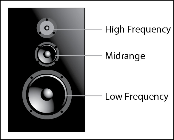
Figure 4-15 Multidriver loudspeaker
So that each driver is sent only those frequencies that it will transduce accurately, an electrical frequency–dividing device called a crossover is used. The crossover device may be placed before the amplification stage, which then supplies only the appropriate signal for its intended driver speaker, or it may be placed on the amplifier’s input to a multidriver loudspeaker cabinet. Many low power–handling loudspeaker cabinets incorporate an unpowered (passive) crossover network to divide the frequencies of the incoming signal and send them to the appropriate driver.
The following are examples of the different drivers and frequency ranges:
• Tweeters, for high frequencies
• Horns, for mid to high frequencies
• Cone or midrange for midrange frequencies
• Woofers, for low frequencies
• Subwoofers, for lower frequencies
Loudspeaker Sensitivity
A loudspeaker’s efficiency rating is based on its ability to convert electrical energy into acoustic energy. As with microphones, this rating is called its sensitivity. This defines the loudspeaker’s acoustic output signal level, given a specified reference input level. Driven by the same reference signal, a more sensitive loudspeaker provides a higher acoustical energy output than a less sensitive loudspeaker.
Although loudspeakers may vary widely in acoustic efficiency; sensitivity—or the lack of it—is not a measure of the acoustic accuracy the loudspeaker. Like microphones, loudspeakers are designed and chosen to meet very specific criteria. Uses include emergency notification, paging, speech reinforcement, music reinforcement, recording studios, sports arenas, foldback, touring concerts, broadcast, system monitoring, audio and video conferencing, houses of worship, and music replay. There is probably nothing else in an AV system that comes in as many different configurations and prices—and for as many different uses—as loudspeakers.
The following is an example of a loudspeaker sensitivity specification:
88dB/1W @ 1m
This means that 88dB SPL will be measured 1 meter away from the loudspeaker with 1 watt input.
Loudspeaker Frequency Response and Polar Patterns
With loudspeakers, as with directional microphones, the overall frequency response will be best on-axis (directly in front of the loudspeaker). As you move off-axis, not only will the sound level be reduced, but the frequency response will also change.
A loudspeaker with specifications showing a nominal dispersion (coverage) pattern holds that pattern only over a limited, high- to mid-frequency range. As lower frequencies spread out quite quickly because of their much longer wavelengths, very large waveguides and enclosures are required to control the dispersion pattern at lower frequencies.
A graphical representation of the loudspeaker’s directional versus frequency response characteristics is called a polar plot. Figure 4-16 shows an example of a loudspeaker polar plot.

Figure 4-16 A loudspeaker polar plot
Loudspeaker Impedance
Loudspeakers have a nominal impedance rating, but because impedance is frequency dependent, this nominal rating will not be true across the loudspeaker’s entire frequency range. Most speakers are rated at 4, 8, or 16 ohms.
When you connect loudspeakers, you need to know the total impedance of the load that you are connecting to the output of the power amplifier. Knowing the total impedance helps to
• Achieve optimum system volume
• Avoid wasting power
• Avoid overloading and damaging your power amplifier
• Prevent damage to your loudspeakers
• Reduce distortion and noise
• Avoid uneven sound distribution
Audio Signal-Level Monitoring
Now that you have looked over the audio-signal path all the way through and know the signal levels involved (mic, line, and loudspeaker), you need to be able to monitor and adjust the signal levels at various points in the system to make sure the signal levels aren’t too low or too high.
Checking Signal Levels
Before turning on any system power amplifiers, check to make sure you are getting clean signals on all the audio mixer channels to be used. Make the necessary level adjustments to the microphone preamplifier and all other gain stages in the mixer and the other audio equipment leading to the power amplifier, verifying that no signal is distorted. Usually, you will check signal levels in the audio mixer with the aid of the built-in level indicators and verify them using headphones.
NOTE It is good practice not to have any single gain stage at its maximum level. This practice tends to reduce the electronic noise and distortion introduced into the signal path.
After setting the gain stages, follow these steps:
1. Turn the power amplifier input adjustments all the way down.
2. Turn on the power amplifier.
3. Slowly bring up the power amplifier input adjustments until you reach the desired sound pressure level at the loudspeakers.
4. Verify that no signals are distorted by listening to the system and monitoring the signals.
These practices will help prevent signal levels that are too low, resulting in poor signal-to-noise levels, and will help prevent signal levels that are too high, resulting in distortion.
With analog metering systems, it is generally preferred to keep line-level signal levels at around 0dBu (775mV), although there will be moments during normal usage when the signal level exceeds 0dBu.
However, with digital signal metering, the level must never exceed 0dBFS (the full scale of the digital signal) as any signal beyond this level will be clipped and become distorted.
Frequently, equipment will provide at least a single LED indicator of the signal-level condition. Some LEDs may even change color as the signal level approaches or goes into distortion. LED labels may include the following:
• Signal present
• Overload
• Clip
NOTE Read the equipment’s manual. It will help you to make sure you operate the equipment properly and understand what a specific indicator tells you about the condition of the signal. Quite often, you will find that a red, flashing LED indicates signal distortion. Let’s face it—you should always read the equipment manuals.
Balanced and Unbalanced Circuits
All electrical circuits—and the cabling used to connect them—generate electromagnetic energy fields that interact with other electrical circuits and cabling, including AV circuitry and cabling. This interference and noise degrade the quality of the signal and, in an audio system, may introduce hum, buzz, crackles and splats.
One way to reduce the noise in a circuit is to use an actively balanced electrical circuit, as shown in Figure 4-17, which offers a defense mechanism against noise. In a balanced circuit, the signal is transmitted over two identical parallel wires. These signals are said to be in-balance. At the receiver, the signals are combined. This produces a higher-strength signal but more importantly cancels out any external signals picked up by both wires. This cancellation process is known as common mode rejection. As a general rule, balanced circuits are used wherever possible in audio, despite the cost premium. In audio cables, the two signal conductors are usually twisted around each other and surrounded by a shield that is tied to electrical ground. This type of cable is known as shielded twisted-pair cable, as shown in Figure 4-18.

Figure 4-17 A balanced circuit. The interference signal spikes are cancelled out by inversion.
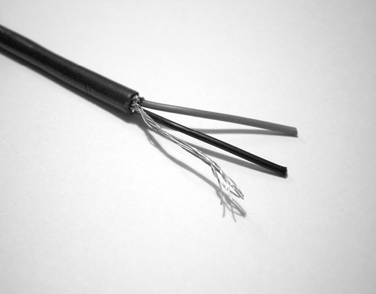
Figure 4-18 A shielded twisted-pair cable
In the lower-cost unbalanced circuit, as shown in Figure 4-19, the signal is transmitted down a single signal wire. Without the second, inverted signal, to provide common mode rejection, all external signals picked up by the signal wire will be present in the system output. The single conductor in an unbalanced cable is usually surrounded by a cable shield that also acts as the return electrical path for the circuit. Unbalanced circuits are also known as single-ended circuits.
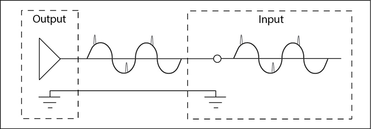
Figure 4-19 An unbalanced circuit. The interference signal spikes pass through the circuit.
With either a balanced or unbalanced design, the longer the cable run, the more noise the cabling is subjected to. Therefore, unbalanced lines are extremely limited in the distance they can cover and their ability to transfer a usable signal.
A quick way to determine whether a piece of equipment is balanced or unbalanced is to look at its outputs or inputs. Unbalanced audio equipment and cables typically have only one pin or segment per signal, plus one return connector. The most common of these are the RCA (phono) plug and the 3.5mm (1/8in) jack plug. While a three-section 3.5mm (TRS) jack plug is in wide use on portable equipment and computers, this connecter is used only in unbalanced circuits. It actually carries two separate unbalanced signals: the left and right channels of a stereo signal, plus a common signal return wire. The most common connector used in balanced-line systems is the three-pin XLR. These common connector types can be seen in Figure 4-20.

Figure 4-20 Common audio connectors
Feedback
Acoustic feedback is the squealing or howling sound sometimes heard from audio systems. It is generated when a system’s output is fed back into its input. This usually occurs when the output from the system’s loudspeakers is picked up by the system’s microphones and repeatedly re-amplified, forming a feedback loop. A system in feedback is considered to be unstable. Feedback can occur either if a microphone is too close to the front of a loudspeaker or if the gain (volume) has been turned up too high somewhere in the sound system.
One way to avoid feedback is through proper microphone and loudspeaker placement. Some best practices for controlling feedback include the following:
• Keep each microphone as close to its sound source as possible.
• Keep the loudspeakers in front of, and as far from, the microphones as is practical.
• Select directional microphones with polar patterns that fit the usage requirements.
• Select loudspeakers with coverage patterns that cover only the audience area.
• Keep all gains to the minimum levels required for optimum system effectiveness.
Examples of Audio System Applications
We’ve reviewed the audio signal chain from start to finish—from microphones to loudspeakers. You’ve also learned about the various signal levels, cable used, and types of circuits (balanced) preferred by the audio professional. Now it’s time to identify a few common audio system applications.
Sound Reinforcement or PA
If you can’t hear something at an adequate level acoustically (unamplified), then microphones, audio mixers, signal processors, power amplifiers, and loudspeakers are used to electronically amplify that sound source so you can hear it and distribute it to a larger or more distant audience.
In general, sound reinforcement comes in two variations: music and speech reinforcement. In live production, a sound reinforcement system is often referred to as a PA (public address) system, the name originally given to simple speech-reinforcement systems. Depending on the musical content, music-reinforcement systems may need to cover a substantial proportion of the audible spectrum and therefore tend to be full-bandwidth systems, capable of reproducing a wide frequency range with high sound pressure levels. Speech-reinforcement systems are used in situations where an audience can’t adequately hear an unamplified presenter. Because the human voice has limited bandwidth, a speech-reinforcement system may not need to be designed for full bandwidth.
Mix-Minus
A “mix-minus” system is a special type of sound-reinforcement system where some elements of the full sound mix have been deliberately omitted. A mix-minus system is often used when there is a strong possibility of system feedback because of the close proximity of loudspeakers and microphones. When meeting participants, as well as the presenter, must be heard, microphones are distributed and mixed carefully with each group of loudspeakers. This can present challenges in making the system work without becoming unstable, because placing a live microphone near the loudspeaker amplifying its signal would cause feedback. It is also common to use mix-minus feeds for musicians and singers who require a local “foldback” speaker to enable them to hear some of their own voice and only some of the other musicians in the performance.
The approach is to create a separate sound subsystem for each loudspeaker or group of loudspeakers (called loudspeaker zones). The term mix-minus means each subsystem mixes the microphone signals, minus (or except) those microphones that may cause local echoes or feedback.
Intercom and Paging Systems
Intercoms are sound systems used for intercommunication between people or rooms. Usually, but not always, the people/rooms are located within the same building or complex of buildings. These systems typically comprise a central unit with local (personal) stations. They may also include multiple satellite or remote stations. The purpose is to provide two-way communication in the same way that a telephone provides two-way communication.
Paging systems are for one-way communication only. They are often used for information that needs to be communicated to a large audience. Paging systems can be simple, such as a system used for occasional announcements at a supermarket, or they can be complex, such as an emergency notification system used during life-threatening situations. With a paging system, the emphasis is on coverage and intelligibility.
Playback Systems
A playback system is similar to a music reinforcement system but does not utilize microphones. Instead, it simply plays the audio components of prerecorded material and data streams. A single, well-designed audio system can often be used for speech reinforcement, music reinforcement, and playback.
Audioconferencing and Audio for Videoconferencing
Conferencing—and audioconferencing in particular—is communication between groups of people, often in different locations. Depending on the size of the group, multimicrophone audioconferencing modules may be placed on tables between the participants or suspended from the ceiling above them. Large groups may require multiple individual microphones installed on tables as part of a larger integrated AV system. An audioconferencing system often includes DSP-based acoustic echo-cancellation, gating, and level-compression technologies. Systems may also include speech-reinforcement, auxiliary source inputs, streaming, and playback capabilities.
Audio for videoconferencing is often a version of an audioconferencing system designed to support a videoconference, with the major difference being the more discreet placement of microphones.
Sound Masking
In almost every other type of audio system, it is important to minimize background noise. With a sound-masking or speech privacy system, background noise is deliberately introduced into to an environment to reduce the intelligibility of distant conversations, thus aiding speech privacy. The sound-masking system also helps to reduce distractions caused by other noises, such as those caused by mechanical systems and external street traffic.
Chapter Review
In this chapter, you learned about the basics of sound propagation, sound wave frequency and wavelength, harmonics, decibels, and the sound environment. With these as a foundation, you learned how to apply the basics of sound to the electrical pathway used to amplify speech, music, and other audio.
The electrical audio-signal chain, from start to finish, consists of everything from microphones to mixers and processors to loudspeakers. Each device in an audio system has varying features and characteristics, which the AV professional chooses among based on client need.
Review Questions
The following review questions are not CTS exam questions, nor are they CTS practice exam questions. Material covered in Part II provides foundational knowledge of the technology behind AV systems, but it does not map directly to the domains/tasks covered on the CTS exam. These questions may resemble questions that could appear on the CTS exam but may also cover material the exam does not. They are included here to help reinforce what you’ve learned in this chapter. See Appendix D for more information on how to access the online sample test questions.
1. How sound moves through the air is called_____.
A. Generation
B. Compression
C. Acoustical
D. Propagation
2. Wavelength is the _____.
A. Number of times a wavelength cycle occurs per second
B. Intensity or loudness of a sound in a particular medium
C. Physical distance between two points of a waveform that are exactly one cycle apart
D. Cycle when molecules move from rest through compression to rest to rarefaction
3. Which of the following does 0dB SPL describe?
A. The threshold of human hearing
B. Ambient noise level
C. The threshold of pain
D. Normal listening level
4. A “just noticeable” change in sound pressure level, either louder or softer, requires a _____ change.
A. +/–10dB
B. +/–6dB
C. +/–1dB
D. +/–3dB
5. Acoustics covers how sound is _____, and its _____ and _____.
A. Received; effects; structure
B. Produced; propagation; control
C. Controlled; delivery; translation
D. Produced; amplification; reception
6. Numerous, persistent reflections of sound are called _____.
A. Directional sound
B. Echo
C. Surface reflection
D. Reverberation
7. Ambient noise is sound that _____ the desired message or signal.
A. Interferes with
B. Completely blocks
C. Enhances
D. Is louder than
8. The audio signal ends up in a(n) _____ before being converted into acoustical energy.
A. Output device
B. Electrical signal
C. Processor
D. Microphone
9. The strength of the electrical audio signal from a microphone is called a(n) _____ -level signal.
A. Dynamic
B. Condenser
C. Electret
D. Mic
10. Phantom power is the _____ required to power a condenser microphone.
A. Polarized conductor
B. Electrical field
C. Remote power
D. Internal capacitor
11. Typically, what type of connector finishes the shielded twisted-pair cable?
A. XRL
B. RXL
C. LRX
D. XLR
12. The simultaneous use of multiple wireless microphone systems requires ____.
A. Frequency coordination
B. Multiple receivers all tuned to the same frequency
C. Using lavalier microphones
D. Using IR wireless microphones
13. If a technician changes the level of a signal, it is called _____.
A. Unity gain
B. Gain adjustment
C. Attenuation
D. Signal expansion
14. The amplifier comes right before _____ in the audio system chain.
A. The equalizer
B. Everything
C. The audio processor
D. The loudspeakers
15. What is a crossover?
A. A loudspeaker containing multiple drivers
B. A loudspeaker enclosure with more than one frequency range
C. An electrical frequency dividing network circuit
D. A single driver reproducing the entire frequency range
Answers
1. D. How sound moves through the air is called propagation.
2. C. Wavelength is the physical distance between two points of a waveform that are exactly one cycle apart.
3. A. 0dB SPL describes the threshold of human hearing.
4. D. A “just noticeable” change in sound pressure level, either louder or softer, requires a +/–3dB change.
5. B. Acoustics covers how sound is produced and its propagation and control.
6. D. Numerous, persistent reflections of sound are called reverberation.
7. A. Ambient noise is sound that interferes with the desired message or signal.
8. A. The audio signal ends up in an output device before being converted into acoustical energy.
9. D. The strength of the electrical audio signal from a microphone is called a mic-level signal.
10. C. Phantom power is the remote power required to power a condenser microphone.
11. D. An XLR connector typically finishes the shielded twisted-pair cable.
12. A. The simultaneous use of multiple wireless microphone systems requires frequency coordination.
13. B. If a technician changes the level of a signal, it is called gain adjustment.
14. D. The amplifier comes right before the loudspeakers in the audio system chain.
15. C. A crossover is an electrical frequency–dividing network circuit.