CHAPTER 7
Signal-Management Systems
In this chapter, you will learn about
• Wiring and cable for AV systems
• Ensuring signal integrity and distribution amplifiers
• Rack building
Think of a signal-management system as a number of individual elements that work together to achieve a goal. The individual elements include signal-management devices, cables, wires, and connectors. These elements work together to achieve effective signal transfer. If you properly assemble and configure the working parts of a signal-management system, you can preserve the quality of the signal throughout the system.
A signal is the desired information sent through an AV system. Some examples are video, audio, data, and control signals. Undesirable elements introduced into the system are considered noise and interference.
In most cases, signals are transported through an AV system by wires, cables, and wireless links. Each cable in a system has a specific purpose and physical destination. A cable designed for use with a video camera or a media player may contain multiple wires for video, power, and other functions.
Signal types can be grouped together so that their path through the system is easier to trace. This path is referred to as signal flow. There may be separate flows for video, audio, and control.
In this chapter, you will learn about the components of signal-management systems.
Wire and Cable
The terms wire and cable are often used interchangeably; however, each has its distinct characteristics.
A wire contains only one signal conductor. That conductor may be either solid or composed of strands of conductive material. In electronics, a conductor is made of a material that easily conducts an electrical signal. Insulation around the conductor is composed of materials that do not efficiently conduct electrical signals. The insulation provides physical and electrical protection to the conductor.
A cable contains multiple insulated wires in a protected bundle, as shown in Figure 7-1. Some types of cables contain one or more shields that add protection to the integrity of the signal carried by the conductors. A shield helps prevent noise from mixing with the signal. A jacket covers the internal components of a cable and provides protection from abrasion and environmental factors. Here, you’ll learn more about each of these elements.
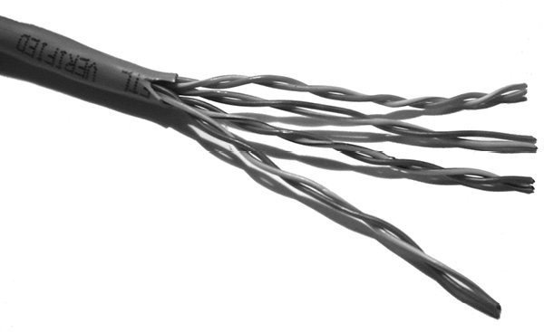
Figure 7-1 A Category 5 cable with four unshielded twisted pairs of wires
Conductors
A conductor is a material that allows a current to pass through it continuously. Some metals make excellent conductors because they are inexpensive and easy to work with. The conductor in a wire carries the signal by conducting current between a source, such as a microphone, and a load, such as a mixing console.
Conductors may be classified by the following:
• Size (gauge or cross-sectional area)
• Construction
• Conductive material
A solid conductor is a single-strand conductor and costs less than a multistranded conductor. Solid conductor wire is less flexible than stranded wire and has more restrictive bend-radius limitations. The bend radius dictates how much you can bend the cable before it deforms and alters its electrical properties. Although this type of cable is relatively inflexible, it can generally withstand more strain than a stranded conductor of similar cross-sectional area. Single-stranded cables are not suitable for applications where regular flexing is required.
A stranded conductor uses multiple smaller, solid conductors that are twisted or braided together, as shown in Figure 7-2. The finer the strands, the more flexible the conductor, which enables easier handling and installation.
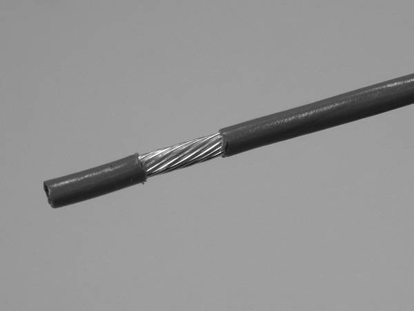
Figure 7-2 A stranded conductor
Stranded conductors are more flexible and easier to handle than solid conductors, but they are more expensive. They are also slightly larger than solid conductors of a similar cross-sectional area.
Stranded conductors are used where flexibility is required, such as for patch leads or in a live-event environment, where the cable needs to be flexed and moved around frequently. In situations like these, the flex life of a cable becomes an important consideration. Flex life is a general term that describes how long a wire may last before it physically fails to conduct signals properly.
The cross-sectional area, or gauge, of the conductors in a wire must be sufficient to handle the intended signal’s current without offering too much electrical resistance or producing too much heat.
Insulation
The purpose of insulation, shown in Figure 7-3, is to prevent physical contact between multiple conductors and to avoid signal interactions between different conductors. If bare wires touch, they can create short circuits that prevent signal transmission and damage equipment. To prevent such problems, insulation, which is a highly resistive material, surrounds the conductors.

Figure 7-3 Two conductors with insulation
In general, insulation is made from materials such as PVC, silicone, rubber, or PTFE (Teflon). Different types of insulation can impact the performance of wire. The ability of an insulating material to block electric fields is known as its dielectric strength.
Heat has an opposite effect on an insulator than it has on a conductor. While most conductors increase in conductivity with temperature, higher temperatures result in lower dielectric strength in an insulator.
Shields
Shielding isolates and protects a signal from sources of electromagnetic (EM) interference. Cables may or may not have a shield.
Shields (sometimes called screens) can be implemented in a variety of ways. They can be used to provide overall coverage around a single insulated conductor or around individual or groups of insulated conductors in a multiconductor cable. A single shield can also be used to surround multiple insulated conductors.
There are three basic types of shielding:
• Foil shield This type of shielding uses aluminum foil wrapped around an insulated conductor or conductors. For termination purposes, an additional uninsulated conductor in continuous contact with the foil shield is used. The bare conductor provides an electrical drain or ground connection.
• Braided shield This type uses fine, uninsulated wires to form an interwoven cover over an insulated conductor or conductors. Some braided shields are woven in multiple layers to improve shielding. Ground or drain termination is made directly with the braided shield.
• Combination shield This type uses both foil and braid shielding, with the possible addition of a drain wire. Figure 7-4 shows an example of foil and braid shielding.

Figure 7-4 A coaxial cable showing foil and braid shielding
The main considerations in selecting a shield are coverage, flexibility, and frequency range. Coverage is expressed as a percentage and indicates how much of the inner cable will be covered. Flexibility is a subjective measurement, which directly correlates to a cable’s flex life. Not all shielding can protect the enclosed conductor from all sources of EM interference. Because of this, a shield’s effectiveness is narrowed to a certain frequency range.
Shielding is also used to protect other devices and cables from the EM radiation generated by the signals in the enclosed circuit.
Jackets
Jackets (also called sheaths) provide physical protection to a cable. They surround and protect the inner wire or wires and insulate the conductors from environmental factors. If the cable has a shield, the jacket is placed over the shield; otherwise, it is placed directly over the insulated wires.
Jackets are selected for their strength, integrity, abrasion resistance, and overall protection. Additional considerations are the environmental factors, such as UV radiation and corrosive vapors that can deteriorate the cable; color (for aesthetic, identity, or labeling concerns); flexibility; flammability; emissions on combustion; and electrical code requirements.
Most jacket materials are the same ones used for insulation. The choice is dictated by the application. Some plastics are unsuitable for use in certain locations because of their flammability or the toxic chemicals they produce if subjected to fire. PTFE (Teflon) will withstand high heat, not support a fire, and produce very little smoke. It is, however, hard to work with and more expensive than other materials. Silicone is flexible, robust, and easy to work with, and it can withstand high temperatures. Jacket materials are the subject of continuing research and innovation, with new materials being introduced regularly.
Cable Types
You should be familiar with three basic cable types: coaxial (coax), twisted-pair, and fiber-optic.
Coax Cable
Coax cable contains a single conductor that is surrounded by insulation (see Figure 7-4, earlier in the chapter). Around the insulation can be one or two types of shields and a jacket. The first shield maybe a foil or a braid; if present, the second shield is usually braided. The term coax arose from the fact that the shielding and center conductor are coaxial (they both have the same central axis).
Coaxial cable is unbalanced. The single wire running down the center is the signal conductor, and the shield acts as the return. The impedance of coaxial cable is mostly dependent on the capacitive coupling between the central conductor and the shield, which is strongly influenced by the dielectric strength of the insulation surrounding the central core. Typical nominal impedances for coaxial cables are 75Ω, used for video applications, and 50Ω, used for data and radio frequency applications. The two types of cable are not interchangeable.
Twisted-Pair Cable
Twisted-pair cable is composed of pairs of insulated wires twisted around each other. Pairs of wires may also be shielded to avoid crosstalk (signal interference) with other pairs in the cable, and the entire cable may also have a shield to reduce external interference. Spacing materials may be introduced between pairs to further reduce crosstalk. Twisting, when used in combination with balanced circuitry, helps reject common mode interference.
Fiber-Optic Cable
Fiber-optic cable uses conductors that are made from transparent glass or plastic fibers, as shown in Figure 7-5. Because the conductors are transparent, visible light or infrared (IR) signals can be transmitted instead of a current.

Figure 7-5 Fiber-optic cable
There are two types of fiber-optic cable:
• Single-mode Single-mode means that the transmitted light travels a single light path. You can typically identify single-mode fiber-optic cable by its yellow outer protective jacket.
• Multimode Multimode means it travels multiple light paths. Multimode fiber-optic cable is identified by an orange jacket.
The signals that travel along single-mode fiber can reach farther distances without attenuation than signals on multimode because of the construction of the cable.
Connectors
Connectors are terminated onto (attached to) cables and used on equipment to continue the pathway to the electronics inside. The type of connector used on the cable must be compatible with the connector type used on the equipment for a reliable connection. Connectors can be categorized by the way they mate:
• Twisting
• Twist and locking
• Threading
• Screw or snap-down lock
• Contact pressure
As illustrated in Figure 7-6, the following are some common connector types:

Figure 7-6 Some standard signal cable connectors
• XLR Used for sending audio and control signals and for supplying power. The connector is typically found on microphones, audio mixers, amplifiers, headsets, audio-processing devices, communications systems, and lighting control systems.
• 6.5mm (1/4-inch) phone Used to transport signals between audio devices. It is typically found on audio patch panels, musical instruments, audio mixers, and amplifiers.
• 3.5mm (1/8-inch) phone Used to carry audio or control signals on consumer and computer devices. It is typically found on headphones, computer loudspeakers, laptop and tablet computers, personal music and multimedia devices, and a variety of other places.
• RCA (phono) Carries unbalanced video signals, audio signals, or control signals. It is found on consumer video devices, audio devices, control systems, switching systems, and signal converters.
• F type Carries RF, composite video, and audio signals. It is commonly found on antennas, consumer video recorders, set-top boxes, and televisions.
• DB9 Used for control signals.
• RJ-45 (8P8C or 8-pin, 8-conductor) Used for data networking, control, HDBaseT multimedia, and telephone purposes. It is often found on projectors, matrix switchers, laptops, system-control devices, and network devices.
• BNC Used to transport different types of signals, including RF, component video, time code, sync, and SDI. It is often found on wireless equipment that connects to an external antenna and on some video equipment and projectors. The Serial Digital Interface (SDI) and its higher bandwidth derivatives are covered in Chapter 5.
• Speakon (NL4) A four-pole loudspeaker connector commonly used to connect amplifiers to loudspeakers in professional audio systems. The two-pole (NL2) and eight-pole (NL8) variants are also used. The PowerCon, a close relative of the Speakon, is used for mains power connections to audio, lighting, and AV systems.
• Captive screw Designed with screws that secure the connector to the conductors within the cable. These are also known as Euroblock or Phoenix connectors.
• DVI (Digital Visual Interface) Used to carry digital and analog video, plus video control signals through a 29-pin connector. By omitting some of the pins, variants of the DVI connector carry digital video only (DVI-D); VGA-compatible analog video only (DVI-A); dual digital video streams (DVI-DL); or the full integrated system of digital, analog, and control signals (DVI-I).
• HD15 (VGA) Sometimes incorrectly called a DB15 (DB15 has two rows of pins, while HD15 has three rows of pins). This is found on computers and monitors that use analog video signals.
• HDMI (High-Definition Multimedia Interface) HDMI builds on the DVI standard by adding audio, EDID device control, HDCP content protection, and Ethernet. HDMI is backward-compatible with DVI. The HDMI connector comes in HDMI, Mini-HDMI, and Micro-HDMI versions.
• DisplayPort DisplayPort also builds on the success of DVI and uses a similar, yet not completely compatible, format to send video and audio. DisplayPort is also available in a Mini-DisplayPort version. This is used for consumer and professional computer and video displays.
• USB (Universal Serial Bus) Used for general-purpose serial data connections between computers and their peripherals. Signals carried include video and audio streams, device control, network data, and storage access. USB connectors come in a range of square (type B) and rectangular (type A) formats and sizes, including the oval, nonpolarized type C.
Signal Integrity
As a signal travels along conductors through an AV system, it is important to protect its quality. You need to arrange cables that carry signals in a way that minimizes interference from sources of noise. The goal is to preserve the signal’s integrity until it arrives at its destination.
Capacitance occurs when two conductors are separated by a nonconductive material. The electrostatic field set up between the conductors stores some charge. The amount of charge stored is governed by the area of the conductors, the distance between them, and the dielectric strength of the material separating them. The capacitance of an electric circuit acts to oppose changes of voltage in the circuit. The higher the frequency of the signal in a circuit, the lower the capacitive losses. Significant capacitance between the wires in a cable can attenuate and distort the signal carried in the cable.
In addition, each wire in a cable can act as an antenna, collecting signals from other wires in the cable—a phenomenon known as crosstalk.
One way to protect signal integrity is to group cables together by signal type and then physically separate the groups. Cables that carry microphone-level signals should be bundled together only with other microphone-level cables. Similarly, cables that carry line-level signals should be bundled together only with other line-level cables. Placing cables that carry different voltages and frequencies near each other creates an environment where the individual signals can mutually interfere.
It is important to avoid running cables near electrically noisy sources, such as motors, fluorescent or dimmed lighting, power distribution cables, and electrical power control systems. Other sources of noise include battery charging and radio transmitter systems.
All of these situations can cause signal degradation and loss. Signal degradation can take many forms: voltage amplitude reductions, changes in the shape of the signal’s waveform, or phase shifting.
Generally, analog signal systems are much more susceptible to problems arising from noise and distortion than digital systems. The best way for you to preserve signal integrity is through proper system design and installation using industry best practices and established performance standards.
Distance Limits
A signal transmitted at the proper level will lose strength or amplitude over distance. The important factors in determining how far a signal will travel are signal level, signal bandwidth, and the loss factors of the cable type used. Every signal type has unique characteristics. It is important to consult published standards and cable manufacturers’ documentation to determine transmission distance limits based on signal type and frequency.
In general, digital signals do not travel as far as analog signals without some form of buffering or amplification. Each type may also require a unique cable configuration when splitting or looping them within a system.
Switchers
A switcher is a device that allows users to select among two or more sources and send the selected signal to a particular destination. With an audio switcher, you can connect the outputs from an AM/FM tuner, a DVD player, a computer output, and a media player to the inputs of a switcher. Then you can connect the output of the switcher to a single-input amplifier. Choosing which source you want to listen to is as easy as selecting that source on the switcher. Switchers may be separate components, built into audio processing devices or included in a digital signal processor (DSP). Similarly, video switchers can be used to select between the signals from different devices to feed a video monitor, projector, recorder, or distribution system.
Switchers can be passive (do not require power to operate), but many are active. Active switchers can provide some adjustable amplification, equalization, and buffering on each input so that switching does not produce disturbances on the output.
Switcher Ins and Outs
Switchers are defined by the number of inputs (ins) and outputs (outs) they support. They can send only one of their multiple inputs to their output, as opposed to mixers, which can send a combination of several sources to a destination simultaneously.
A matrix switcher is capable of selecting any of its input sources to simultaneously go to one or more of its outputs. It is effectively a composite of several switchers, as illustrated in Figure 7-7. The number of switchers required is the number of outputs specified by the size of the matrix. For example, a 4 × 2 matrix switcher effectively contains two four-input switchers. To avoid loading at the inputs, each input contains a distribution amplifier, which distributes the input source to the equivalent input of every switcher contained in the matrix.

Figure 7-7 A four-in, four-out matrix switcher diagram
Switcher Types
Two specific switcher types are mechanical and seamless. As you might guess, a mechanical switcher has a mechanical connection of the cables or circuit. It functions like a wall switch, meaning there is a mechanical connection or disconnection between two conductors.
Mechanical switchers pay no attention to a signal’s content. This may not be a serious problem for switching analog audio, but it is a major issue when switching video or network data that come in discrete frames or packets. For example, if a media player and video camera is connected to a mechanical switcher’s inputs, when a user changes the switcher’s output signal to a monitor, the picture may jump, roll, or break up before it stabilizes. This occurs because the video signals were not at the interval between video frames when switching took place, so incomplete parts of two video frames were displayed. For this reason, mechanical video switchers are sometimes referred to as crash switchers.
Where visual quality should not be compromised, seamless switchers are used instead of mechanical switchers. Seamless switchers use electronic circuitry to monitor the sync information from the two sources, buffer the video signal, and make the transition during the interval between frames. Transitions from source to source are clean and seamless.
Distribution Amplifiers
A distribution amplifier (DA) is an amplifier with a gain of one. It does not increase signal levels; instead, it allows a single input signal to be distributed to multiple outputs while maintaining the original signal level and quality. Audio and video distribution amplifiers (VDAs) are widely used in professional AV systems. Figure 7-8 shows a diagram of an audio system with two distribution amplifiers.
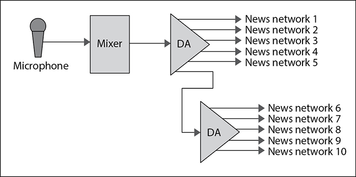
Figure 7-8 Audio system with two distribution amplifiers
Video distribution amplifiers are available for all formats of analog and digital video. They come in balanced and unbalanced versions and a variety of sizes, ranging from as few as two to more than a dozen outputs. Video distribution amplifiers may also have audio distribution channels to facilitate simultaneous video and audio distribution.
For example, consider a speech-reinforcement system that requires news media distribution to accommodate up to 24 media feeds. In this way, a speaker may make a presentation at a lectern with one microphone, rather than being obscured from the camera by two dozen microphones. The news media simply connect their recording devices to a socket on an output panel that provides a fixed, isolated signal from the output of a distribution amplifier. If one member of the media has a shorted cable, it would affect only that one feed, rather than causing problems for everyone else.
Rack-Building Considerations
One of the most common places you will find a signal-management system is in an AV rack. An AV rack is a housing unit that protects and organizes electronic equipment. Figure 7-9 shows examples of two AV racks.
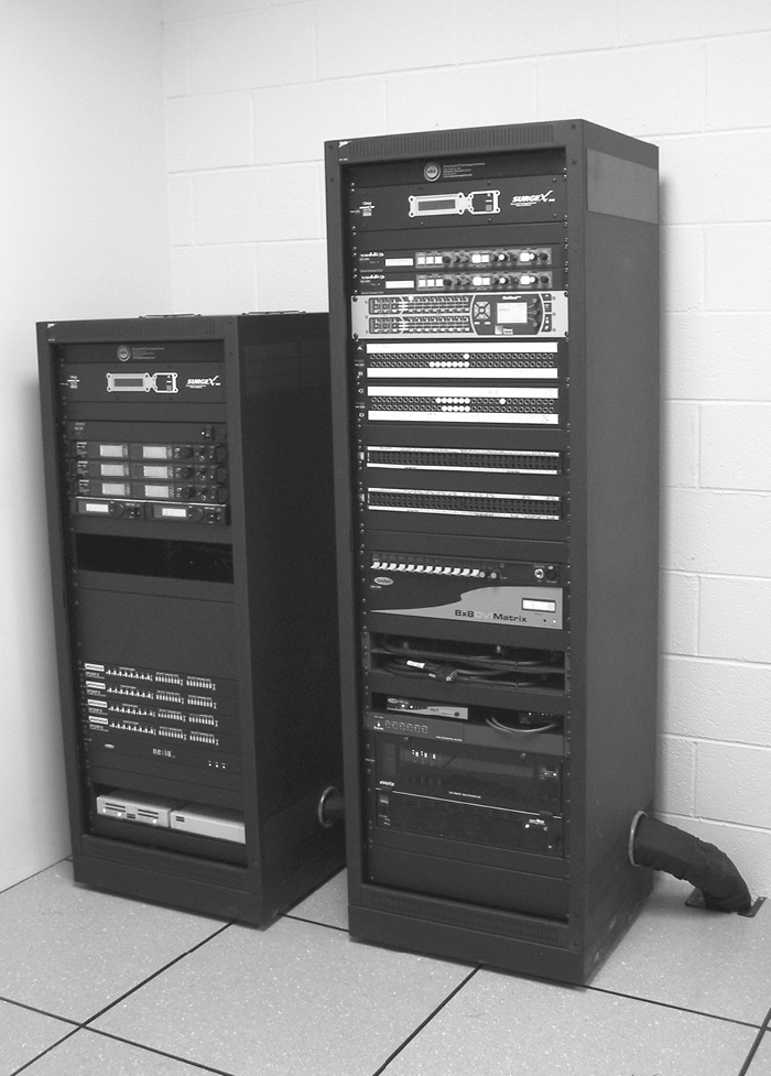
Figure 7-9 Two AV racks
The inside of a typical AV industry rack is 19 inches (482.6mm) wide. Many of the technical specifications for a rack, including size and equipment height, are determined by standards that have been established by numerous standards-setting organizations.
The external width of the rack varies from 533 to 635mm (21 to 25 inches). Racks are also classified by their vertical mounting height. Rack height varies from about 300mm (1 foot) to more than 2.1 meters (7 feet). The measurement of the usable mounting space in a rack is the rack unit (RU), which is equal to 44.45mm (1.75 inches). A 300mm-high rack would be considered a 6RU space, while a 2.1-meter-high rack would be considered a 48RU space.
Most AV equipment is manufactured to be mounted within an AV rack and therefore has mounting points that are an industry-standard 18.312 inches (465mm) center to center. Like racks themselves, equipment height is measured in RUs, with most rack-mountable equipment designed to fit into a whole number of RUs. An audio mixer might be 1RU high, while an amplifier might be 2RUs high. Some equipment, like switchers, can be 10RUs high or even taller.
Designers and installers carefully plan for all the equipment that will go in a rack. One useful tool in the planning process is called a rack elevation diagram. This diagram can show the front and back of a rack and indicate the number of RUs required for each piece of gear. Special consideration is given to how much heat a piece of equipment emits, the types of signals carried to the equipment, and whether the equipment has an interface component for a typical user.
Installers use RUs to calculate necessary vertical-spacing requirements between electronic elements for ventilation and airflow paths in the rear of the rack. All electronic devices produce waste heat that builds up in and around the equipment and must be removed. Many rack-mounting devices have vents on the top and bottom of the chassis so that the hot air can escape. When the hot air is vented from some pieces of equipment, it may flow into the air intakes of other equipment and eventually cause equipment failure. To prevent this problem, vents are used to direct cool air in from the bottom of the rack, which forces the warm air out through the top.
Where racks are freestanding and subject to possible overbalancing, it is common practice to install the heaviest equipment in the bottom of the rack to keep the center of gravity as low as practicable.
Finally, equipment with user interface components, such as devices with removable storage media or user-adjustable controls, should be placed within convenient reach of users. There may be regulations in your location that determine proper placement of components. There are also diagrams that depict the back of a rack and the cables that connect each piece of equipment. These are called signal separation diagrams.
Chapter Review
Signal-management systems transmit AV signals from source to output device. The optimal path traverses various types of wire and cable, selected based not only on the signal itself but also on a client’s requirements.
Maintaining the integrity of a signal so that it provides the intended experience when it reaches, for example, a display, a controller, or a loudspeaker takes planning and an AV design that includes the appropriate signal-management devices.
Review Questions
The following review questions are not CTS exam questions, nor are they CTS practice exam questions. Material covered in Part II of this book provides foundational knowledge of the technology behind AV systems, but it does not map directly to the duties/tasks covered on the CTS exam. These questions may resemble questions that could appear on the CTS exam but may also cover material the exam does not. They are included here to help reinforce what you’ve learned in this chapter. See Appendix D for more information on how to access the online sample test questions.
1. The path on which signal types travel is called _____.
A. Signal flow
B. Signal transfer route
C. Wires and cables
D. Audio and video control
2. The purpose of shielding is to prevent _____ from mixing with the signal.
A. Insulation
B. Jackets
C. Conductors
D. Noise
3. Which of the following differentiates cable from wire?
A. Cable contains a shield.
B. Cable contains only one conductor.
C. Cable contains multiple conductors.
D. Conductors are insulated.
4. Twisted-pair cable using balanced circuitry can help in _____.
A. Keeping noise from audio and video
B. Blocking static
C. Preserving the original transmission
D. Rejecting interference
5. Unless amplified or buffered, digital signals generally do not travel as far as _____ signals.
A. Wireless
B. Analog
C. Fiber
D. Cable
6. Switchers _____.
A. Must have power to operate
B. Mix different inputs to a signal output
C. Connect multiple inputs simultaneously to one output
D. Allow the user to select one input from a number of inputs
7. A 4 × 2 matrix switcher _____.
A. Can connect any of four inputs to one or both of two outputs
B. Must have only one output connected at any given time
C. Can connect either of two inputs to any or all of four outputs
D. Has effectively eight outputs
8. An AV rack is a housing unit that _____ electronic equipment.
A. Identifies
B. Elevates
C. Protects and organizes
D. Cools
9. The inside of a typical AV rack is _____ wide, and the outside varies from _____.
A. 1 foot (305mm); 2 to 7 feet (610mm to 2.13m)
B. 19 inches (482.6mm); 21 to 25 inches (533 to 635mm)
C. 25 inches (635mm); 19 to 21 inches (482.6 to 533mm)
D. 21 inches (533mm); 19 to 25 inches (482.6 to 635mm)
Answers
1. A. The path on which signal types travel is called signal flow.
2. D. The purpose of shielding is to prevent noise from mixing with the signal.
3. C. Cable contains multiple conductors.
4. D. Twisted-pair cable using balanced circuitry can help in rejecting interference.
5. B. Unless amplified or buffered, digital signals generally do not travel as far as analog signals.
6. D. Switchers allow the user to select one input from a number of inputs.
7. A. A 4 × 2 matrix switcher can connect any of four inputs to one or both of two outputs.
8. C. An AV rack is a housing unit that protects and organizes electronic equipment.
9. B. The inside of a typical AV rack is 19 inches (482.6mm) wide, and the outside varies from 21 to 25 inches (533 to 635mm).