Chapter 1. Introduction to Security Technologies
This chapter covers the following topics:
![]() Intrusion detection systems (IDS) and intrusion prevention systems (IPS)
Intrusion detection systems (IDS) and intrusion prevention systems (IPS)
![]() IP Security (IPsec) virtual private networks (VPN)
IP Security (IPsec) virtual private networks (VPN)
![]() Secure Sockets Layer (SSL) VPNs
Secure Sockets Layer (SSL) VPNs
![]() Cisco AnyConnect Secure Mobility
Cisco AnyConnect Secure Mobility
![]() Context-aware security
Context-aware security
![]() Cloud and virtualization security
Cloud and virtualization security
The cost of reported computer and network security breaches at enterprises, schools, and government organizations has risen dramatically during the last several years. Both hints and detailed instructions for creating exploits to break into networks and computer systems are becoming more easily available on the Internet, consequently requiring network security professionals to carefully analyze what techniques they deploy to mitigate these risks.
Security threats vary from distributed denial-of-service (DDoS) attacks to viruses, worms, Trojan horses, SQL injection, cross-site scripting (XSS), and advanced persistent threats (APT). These threats can easily destroy or corrupt vital data, requiring difficult and expensive remediation tasks to restore business continuity, as well as enable cyber-criminals to steal critical data.
This chapter introduces the essentials of network security technologies and provides the necessary foundation for technologies involved in the Cisco Adaptive Security Appliances (ASA) security features and solutions.
Firewalls
The word firewall commonly describes systems or devices that are placed between a trusted and an untrusted network. A detailed understanding of how firewalls and their related technologies work is extremely important for all network security professionals. This knowledge helps you to configure and manage the security of your networks accurately and effectively.
Several network firewall solutions offer user and application policy enforcement that supplies protection for different types of security threats. These solutions often provide logging capabilities that enable the security administrators to identify, investigate, validate, and mitigate such threats.
Additionally, several software applications can run on a system to protect only that host. These types of applications are known as personal firewalls. This section includes an overview of network and personal firewalls and their related technologies.
Network Firewalls
Network-based firewalls provide key features used for perimeter security. The primary task of a network firewall is to deny or permit traffic that attempts to enter or leave the network based on explicit preconfigured policies and rules. Firewalls are often deployed in several other parts of the network to provide network segmentation within the corporate infrastructure and also in data centers. The processes used to allow or block traffic may include the following:
![]() Simple packet-filtering techniques
Simple packet-filtering techniques
![]() Next-generation context-aware firewalls
Next-generation context-aware firewalls
Packet-Filtering Techniques
The purpose of packet filters is simply to control access to specific network segments by defining which traffic can pass through them. They usually inspect incoming traffic at the transport layer of the Open System Interconnection (OSI) model. For example, packet filters can analyze Transmission Control Protocol (TCP) or User Datagram Protocol (UDP) packets and judge them against a set of predetermined rules called access control lists (ACL). They inspect the following elements within a packet:
![]() Source address
Source address
![]() Destination address
Destination address
![]() Source port
Source port
![]() Protocol
Protocol
Note
Packet filters do not commonly inspect additional Layer 3 and Layer 4 fields such as sequence numbers, TCP control flags, and TCP acknowledgment (ACK) fields.
Various packet-filtering firewalls can also inspect packet header information to find out whether the packet is from a new or an existing connection. Simple packet-filtering firewalls have several limitations and weaknesses:
![]() Their ACLs or rules can be relatively large and difficult to manage.
Their ACLs or rules can be relatively large and difficult to manage.
![]() They can be deceived into permitting unauthorized access of spoofed packets. Attackers can orchestrate a packet with an IP address that is authorized by the ACL.
They can be deceived into permitting unauthorized access of spoofed packets. Attackers can orchestrate a packet with an IP address that is authorized by the ACL.
![]() Numerous applications can build multiple connections on arbitrarily negotiated ports. This makes it difficult to determine which ports are selected and used until after the connection is completed. Examples of this type of application are multimedia applications such as streaming audio and video applications. Packet filters do not understand the underlying upper-layer protocols used by this type of application, and providing support for this type of application is difficult because the ACLs need to be manually configured in packet-filtering firewalls.
Numerous applications can build multiple connections on arbitrarily negotiated ports. This makes it difficult to determine which ports are selected and used until after the connection is completed. Examples of this type of application are multimedia applications such as streaming audio and video applications. Packet filters do not understand the underlying upper-layer protocols used by this type of application, and providing support for this type of application is difficult because the ACLs need to be manually configured in packet-filtering firewalls.
Application Proxies
Application proxies, or proxy servers, are devices that operate as intermediary agents on behalf of clients that are on a private or protected network. Clients on the protected network send connection requests to the application proxy to transfer data to the unprotected network or the Internet. Consequently, the application proxy sends the request on behalf of the internal client. The majority of proxy firewalls work at the application layer of the OSI model. Most proxy firewalls can cache information to accelerate their transactions. This is a great tool for networks that have numerous servers that experience high usage. Additionally, proxy firewalls can protect against some web-server-specific attacks; however, in most cases, they do not provide any protection against the web application itself.
Network Address Translation
Several Layer 3 devices can supply Network Address Translation (NAT) services. The Layer 3 device translates the internal host’s private (or real) IP addresses to a publicly routable (or mapped) address.
Cisco uses the terminology of real and mapped IP addresses when describing NAT. The real IP address is the address that is configured on the host, before it is translated. The mapped IP address is the address that the real address is translated to.
Static NAT allows connections to be initiated bidirectionally, meaning both to the host and from the host.
NAT is often used by firewalls; however, other devices such as routers and wireless access points provide support for NAT. By using NAT, the firewall hides the internal private addresses from the unprotected network, and exposes only its own address or public range. This enables a network professional to use any IP address space as the internal network. A best practice is to use the address spaces that are reserved for private use (see RFC 1918, “Address Allocation for Private Internets”). Table 1-1 lists the private address ranges specified in RFC 1918.

It is important to think about the different private address spaces when you plan your network (for example, the number of hosts and subnets that can be configured). Careful planning and preparation leads to substantial time savings if changes are encountered down the road.
Tip
The whitepaper titled “A Security-Oriented Approach to IP Addressing” provides numerous tips on planning and preparing your network IP address scheme. This whitepaper is posted at the following link: http://www.cisco.com/web/about/security/intelligence/security-for-ip-addr.html
Port Address Translation
Normally, firewalls perform a technique called Port Address Translation (PAT). This feature is a subset of the NAT feature that allows many devices on the internal protected network to share one IP address by inspecting the Layer 4 information on the packet. This shared address is usually the firewall’s public address; however, it can be configured to any other available public IP address. Figure 1-1 shows how PAT works.
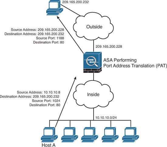
As illustrated in Figure 1-1, several hosts on a protected network labeled “inside” are configured with an address from the network 10.10.10.0 with a 24-bit subnet mask. The ASA is performing PAT for the internal hosts and translating the 10.10.10.x addresses into its own address (209.165.200.228). In this example, Host A sends a TCP port 80 packet to the web server located in the “outside” unprotected network. The ASA translates the request from the original 10.10.10.8 IP address of Host A to its own address. It does this by randomly selecting a different Layer 4 source port when forwarding the request to the web server. The TCP source port is modified from 1024 to 1188 in this example.
Static Translation
A different methodology is used when hosts in the unprotected network need to initiate a new connection to specific hosts behind the NAT device. You configure the firewall to allow such connections by creating a static one-to-one mapping of the public (mapped) IP address to the address of the internal (real) protected device. For example, static NAT can be configured when a web server resides on the internal network and has a private IP address but needs to be contacted by hosts located in the unprotected network or the Internet. Figure 1-2 demonstrates how static translation works.

In Figure 1-2, the web server address (10.10.10.230) is statically translated to an address in the outside network (209.165.200.230, in this case). This allows the outside host to initiate a connection to the web server by directing the traffic to 209.165.200.230. The device performing NAT then translates and sends the request to the web server on the inside network.
Address translation is not limited to firewalls. Nowadays, all sorts of lower-end network devices such as simple small office, home office (SOHO) routers, and wireless access points can perform different NAT techniques.
Stateful Inspection Firewalls
Stateful inspection firewalls provide enhanced benefits when compared to simple packet-filtering firewalls. They track every packet passing through their interfaces by assuring that they are valid, established connections. They examine not only the packet header contents but also the application layer information within the payload. Subsequently, different rules can be created on the firewall to permit or deny traffic based on specific payload patterns. A stateful firewall monitors the state of the connection and maintains a database with this information, usually called the state table. The state of the connection details whether such a connection has been established, closed, reset, or is being negotiated. These mechanisms offer protection for different types of network attacks.
Demilitarized Zones (DMZ)
Firewalls can be configured to separate multiple network segments (or zones), usually called demilitarized zones (DMZ). These zones provide security to the systems that reside within them with different security levels and policies between them. DMZs can have several purposes; for example, they can serve as segments on which a web server farm resides or as extranet connections to a business partner. Figure 1-3 shows a firewall (a Cisco ASA in this case) with two DMZs.

DMZs minimize the exposure of devices and clients on your internal network by allowing only recognized and managed services on those hosts to be accessible from the Internet.
In Figure 1-3, DMZ 1 hosts web servers that are accessible by internal and Internet hosts. The Cisco ASA controls access from an extranet business partner connection on DMZ 2.
Note
In large organizations, you can deploy multiple firewalls in different segments and DMZs.
Deep Packet Inspection
Several applications require special handling of data packets when they pass through firewalls. These include applications and protocols that embed IP addressing information in the data payload of the packet or open secondary channels on dynamically assigned ports. Sophisticated firewalls and security appliances such as the Cisco ASA and Cisco IOS Firewall offer application inspection mechanisms to handle the embedded addressing information to allow the previously mentioned applications and protocols to work. Using application inspection, these security appliances can identify the dynamic port assignments and allow data exchange on these ports during a specific connection.
With deep packet inspection, firewalls can look at specific Layer 7 payloads to protect against security threats. For example, you can configure a Cisco ASA running version 7.0 or later to not allow peer-to-peer (P2P) applications to be transferred over the HTTP protocol. You can also configure these devices to deny specific FTP commands, HTTP content types, and other application protocols.
Note
The Cisco ASA provides a Modular Policy Framework (MPF) that offers a consistent and flexible way to configure application inspection and other features to specific traffic flows in a manner similar to the Cisco IOS Software Modular quality-of-service (QoS) command-line interface (CLI).
Next-Generation Context-Aware Firewalls
The proliferation of mobile devices and the need to connect from any place are radically changing the enterprise security landscape. Social networking sites such as Facebook and Twitter long ago moved beyond mere novelty sites for teens and geeks and have become vital channels for communicating with groups and promoting brands.
Security concerns and fear of data loss are leading reasons why some businesses don’t embrace social media, but many others are adopting social media as a vital resource within the organization. Some of the risks associated with social media can be mitigated through the application of technology and user controls. However, there’s no doubt that criminals have used social media networks to lure victims into downloading malware and handing over login passwords.
Before today’s firewalls grant network access, they need to be aware of not only the applications and users accessing the infrastructure but also the device in use, the location of the user, and the time of day. Such context-aware security requires a rethinking of the firewall architecture. Context-aware firewalls extend beyond the next-generation firewalls on the market today. They provide granular control of applications, comprehensive user identification, and location-based control. The Cisco ASA 5500-X Series Next-Generation Firewalls are examples of context-based firewall solutions.
Personal Firewalls
Personal firewalls are popular software applications that you can install on end-user machines or servers to protect them from external security threats and intrusions. The term personal firewall typically applies to basic software that controls Layer 3 and Layer 4 access to client machines. Today, sophisticated software is available that not only supplies basic personal firewall features but also protects the system based on the behavior of the applications installed on such systems.
Intrusion Detection Systems (IDS) and Intrusion Prevention Systems (IPS)
Intrusion detection systems (IDS) are devices that detect (in promiscuous mode) attempts from an attacker to gain unauthorized access to a network or a host, to create performance degradation, or to steal information. They also detect distributed denial-of-service (DDoS) attacks, worms, and virus outbreaks. Figure 1-4 shows how an IDS device is configured to promiscuously detect security threats.
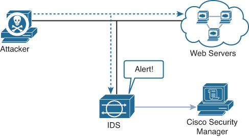
In Figure 1-4, an attacker sends a malicious packet to a web server. The IDS device analyzes the packet and sends an alert to a monitoring system (Cisco Security Manager in this case). The malicious packet still successfully arrives at the web server.
Intrusion prevention system (IPS) devices, on the other hand, are capable of not only detecting all these security threats but also dropping malicious packets inline.
Figure 1-5 shows how an IPS device is placed inline and drops the noncompliant packet while sending an alert to the monitoring system.

Two different types of IPS exist:
![]() Network-based (NIPS)
Network-based (NIPS)
![]() Host-based (HIPS)
Host-based (HIPS)
Note
Examples of NIPSs are the Cisco IPS 4200 sensors, the Catalyst 6500 IPS Module, and the Cisco ASA with the Advanced Inspection and Prevention Security Services Module (AIP-SSM).
The Cisco ASA 5500 Series IPS Solution supplies intrusion prevention, firewall, and VPN services in a single, easy-to-deploy platform. Intrusion prevention services enhance firewall protection by looking deeper into the flows to provide protection against threats and vulnerabilities. Detailed IPS configuration and troubleshooting methodologies are included in Chapter 17. Additionally, Chapter 18 includes information on tuning and monitoring IPS.
Network-based IDS and IPS use several detection methodologies, such as the following:
![]() Pattern matching and stateful pattern-matching recognition
Pattern matching and stateful pattern-matching recognition
![]() Global threat correlation capabilities
Global threat correlation capabilities
Pattern Matching and Stateful Pattern-Matching Recognition
Pattern matching is a methodology in which the intrusion detection device searches for a fixed sequence of bytes within the packets traversing the network. Generally, the pattern is aligned with a packet that is related to a specific service or, in particular, associated with a source and destination port. This approach reduces the amount of inspection made on every packet. However, it is limited to services and protocols that are associated with well-defined ports. Protocols that do not use any Layer 4 port information are not categorized. Examples of these protocols are Encapsulated Security Payload (ESP), Authentication Header (AH), and Generic Routing Encapsulation (GRE) protocol.
This tactic uses the concept of signatures. A signature is a set of conditions that point out some type of intrusion occurrence. For example, if a specific TCP packet has a destination port of 1234 and its payload contains the string ff11ff22, a signature can be configured to detect that string and generate an alert.
Alternatively, the signature could include an explicit starting point and endpoint for inspection within the specific packet.
The benefits of the plain pattern-matching technique include the following:
![]() Direct correlation of an exploit
Direct correlation of an exploit
![]() Trigger alerts on the pattern specified
Trigger alerts on the pattern specified
![]() Can be applied across different services and protocols
Can be applied across different services and protocols
One of the main disadvantages is that pattern matching can lead to a considerably high rate of false positives. False positives are alerts that do not represent a genuine malicious activity. In contrast, any alterations to the attack can lead to overlooked events of real attacks, which are normally referred as false negatives.
To address some of these limitations, a more refined method was created. This methodology is called stateful pattern-matching recognition. This process dictates that systems performing this type of signature analysis must consider the chronological order of packets in a TCP stream. In particular, they should judge and maintain a stateful inspection of such packets and flows.
The advantages of stateful pattern-matching recognition include the following:
![]() The capability to directly correlate a specific exploit within a given pattern
The capability to directly correlate a specific exploit within a given pattern
![]() Supports all non-encrypted IP protocols
Supports all non-encrypted IP protocols
Systems that perform stateful pattern matching keep track of the arrival order of nonencrypted packets and handle matching patterns across packet boundaries.
However, stateful pattern-matching recognition shares some of the same restrictions of the simple pattern-matching methodology, which was discussed previously, including an uncertain rate of false positives and a possibility of some false negatives. Additionally, stateful pattern matching consumes more resources in the IPS device because it requires more memory and CPU processing.
Protocol Analysis
Protocol analysis (or protocol decode-base signatures) is often referred to as an extension to stateful pattern recognition. A network-based intrusion detection system (NIDS) accomplishes protocol analysis by decoding all protocol or client-server conversations. The NIDS identifies the elements of the protocol and analyzes them while looking for an infringement. Some intrusion detection systems look at explicit protocol fields within the inspected packets. Others require more sophisticated techniques, such as examination of the length of a field within the protocol or the number of arguments. For example, in SMTP, the device may examine specific commands and fields such as HELO, MAIL, RCPT, DATA, RSET, NOOP, and QUIT. This technique diminishes the possibility of encountering false positives if the protocol being analyzed is properly defined and enforced. On the other hand, the system can generate numerous false positives if the protocol definition is ambiguous or tolerates flexibility in its implementation.
Heuristic-Based Analysis
A different approach to network intrusion detection is to perform heuristic-based analysis. Heuristic scanning uses algorithmic logic from statistical analysis of the traffic passing through the network. Its tasks are CPU and resource intensive, so it is an important consideration while planning your deployment. Heuristic-based algorithms may require fine tuning to adapt to network traffic and minimize the possibility of false positives. For example, a system signature can generate an alarm if a range of ports is scanned on a particular host or network. The signature can also be orchestrated to restrict itself from specific types of packets (for example, TCP SYN packets). Heuristic-based signatures call for more tuning and modification to better respond to their distinctive network environment.
Anomaly-Based Analysis
A different practice keeps track of network traffic that diverges from “normal” behavioral patterns. This practice is called anomaly-based analysis. The limitation is that what is considered to be normal must be defined. Systems and applications whose behavior can be easily considered as normal could be classified as heuristic-based systems.
However, sometimes it is challenging to classify a specific behavior as normal or abnormal based on different factors, which include:
![]() Negotiated protocols and ports
Negotiated protocols and ports
![]() Specific application changes
Specific application changes
![]() Changes in the architecture of the network
Changes in the architecture of the network
A variation of this type of analysis is profile-based detection. This allows systems to orchestrate their alarms on alterations in the way that other systems or end users interrelate on the network.
Another kind of anomaly-based detection is protocol-based detection. This scheme is related to, but not to be confused with, the protocol-decode method. The protocol-based detection technique depends on well-defined protocols, as opposed to the protocol-decode method, which classifies as an anomaly any unpredicted value or configuration within a field in the respective protocol. For example, a buffer overflow can be detected when specific strings are identified within the payload of the inspected IP packets.
Note
A buffer overflow occurs when a program attempts to stock more data in a temporary storage area within memory (buffer) than it was designed to hold. This might cause the data to incorrectly overflow into an adjacent area of memory. An attacker may craft specific data inserted into the adjacent buffer. Subsequently, when the corrupted data is read, the target computer executes new instructions and malicious commands.
Traditional IDS and IPS provide excellent application layer attack-detection capabilities. However, they do have a weakness: they cannot detect DDoS attacks where the attacker uses valid packets. IDS and IPS devices are optimized for signature-based application layer attack detection. Another weakness is that these systems utilize specific signatures to identify malicious patterns. Yet if a new threat appears on the network before a signature is created to identify the traffic, it could lead to false negatives. An attack for which there is no signature is called a zero-day attack.
Although some IPS devices do offer anomaly-based capabilities, which are required to detect such attacks, they need extensive manual tuning and have a major risk of generating false positives.
Tip
Cisco IPS Software Version 6.x and later support more sophisticated anomaly detection techniques. More information is available at http://www.cisco.com/go/ips.
You can use more elaborate anomaly-based detection systems to mitigate DDoS attacks and zero-day outbreaks. Typically, an anomaly detection system monitors network traffic and alerts or reacts to any sudden increase in traffic and any other anomalies. Cisco delivers a complete DDoS protection solution based on the principles of detection, diversion, verification, and forwarding to help ensure total protection. An example of a sophisticated anomaly detection system is the Cisco CRS Carrier-Grade Services Engine Module DDoS mitigation solution.
You can also use NetFlow as an anomaly detection tool. NetFlow is a Cisco proprietary protocol that provides detailed reporting and monitoring of IP traffic flows through a network device, such as a router, switch, or the Cisco ASA.
Refer to Cisco Feature Navigator to find out in what Cisco IOS image NetFlow is supported. Access this tool at http://tools.cisco.com/ITDIT/CFN/jsp/index.jsp.
NetFlow support was introduced in the Cisco ASA in software version 8.2.
NetFlow uses a UDP-based protocol to periodically report on flows seen by the Cisco IOS device. A flow consists of session setup, data transfer, and session teardown. You can also integrate NetFlow with the Cisco Cyber Threat Defense Solution. Network traffic analysis capabilities provided by the StealthWatch System from Lancope, Cisco’s cyber threat solution partner. Cisco offers the StealthWatch System via its development partnership with Lancope When NetFlow is integrated with the StealthWatch System, you can use statistical profiling to pinpoint day-zero attacks such as worm outbreaks, to take advantage of anomaly detection.
Global Threat Correlation Capabilities
Cisco IPS devices include global correlation capabilities that utilize real-world data from Cisco Security Intelligence Operations (SIO). Global correlation allows an IPS sensor to filter network traffic using the “reputation” of a packet’s source IP address. The reputation of an IP address is computed by Cisco SensorBase using the past actions of that IP address. IP reputation has been an effective means of predicting the trustworthiness of current and future behaviors from an IP address.
Note
More information about Cisco SIO is available at http://tools.cisco.com/security/center/home.x.
Virtual Private Networks
Organizations deploy VPNs to provide data integrity, authentication, and data encryption to assure confidentiality of the packets sent over an unprotected network or the Internet. VPNs are designed to avoid the cost of unnecessary leased lines.
Many different protocols are used for VPN implementations, including:
![]() Point-to-Point Tunneling Protocol (PPTP)
Point-to-Point Tunneling Protocol (PPTP)
![]() Layer 2 Forwarding (L2F) Protocol
Layer 2 Forwarding (L2F) Protocol
![]() Layer 2 Tunneling Protocol (L2TP)
Layer 2 Tunneling Protocol (L2TP)
![]() Generic Routing Encapsulation (GRE) Protocol
Generic Routing Encapsulation (GRE) Protocol
![]() Multiprotocol Label Switching (MPLS) VPN
Multiprotocol Label Switching (MPLS) VPN
![]() Internet Protocol Security (IPsec)
Internet Protocol Security (IPsec)
![]() Secure Sockets Layer (SSL)
Secure Sockets Layer (SSL)
L2F, L2TP, GRE, and MPLS VPNs do not provide data integrity, authentication, and data encryption. On the other hand, you can combine L2TP, GRE, and MPLS with IPsec to provide these benefits. Many organizations use IPsec as their preferred protocol because it supports all three of these features.
VPN implementations are categorized into two distinct groups:
![]() Site-to-site VPNs: Enable organizations to establish VPN tunnels between two or more network infrastructure devices in different sites so that they can communicate over a shared medium such as the Internet. Many organizations use IPsec, GRE, and MPLS VPN as site-to-site VPN protocols.
Site-to-site VPNs: Enable organizations to establish VPN tunnels between two or more network infrastructure devices in different sites so that they can communicate over a shared medium such as the Internet. Many organizations use IPsec, GRE, and MPLS VPN as site-to-site VPN protocols.
![]() Remote-access VPNs: Enable users to work from remote locations such as their homes, hotels, and other premises as if they were directly connected to their corporate network.
Remote-access VPNs: Enable users to work from remote locations such as their homes, hotels, and other premises as if they were directly connected to their corporate network.
Note
Typically, site-to-site VPN tunnels are terminated between two or more network infrastructure devices, whereas remote-access VPN tunnels are formed between a VPN head-end device and an end-user workstation or hardware VPN client.
Figure 1-6 illustrates a site-to-site IPsec tunnel between two sites (corporate headquarters and a branch office).

Technical Overview of IPsec
IPsec uses the Internet Key Exchange (IKE) protocol to negotiate and establish secured site-to-site or remote-access VPN tunnels. IKE is a framework provided by the Internet Security Association and Key Management Protocol (ISAKMP) and parts of two other key management protocols, namely Oakley and Secure Key Exchange Mechanism (SKEME).
Note
IKE is defined in RFC 2409, “The Internet Key Exchange (IKE).” IKE version 2 (IKEv2) is defined in RFC 5996, “Internet Key Exchange Protocol Version 2 (IKEv2).”
IKE has two phases. Phase 1 is used to create a secure bidirectional communication channel between the IPsec peers. This channel is known as the ISAKMP Security Association (SA). Phase 2 is used to negotiate the IPsec SAs.
IKEv1 Phase 1
Within Phase 1 negotiation, several attributes are exchanged:
![]() Encryption algorithms
Encryption algorithms
![]() Hashing algorithms
Hashing algorithms
![]() Diffie-Hellman groups
Diffie-Hellman groups
![]() Authentication method
Authentication method
![]() Vendor-specific attributes
Vendor-specific attributes
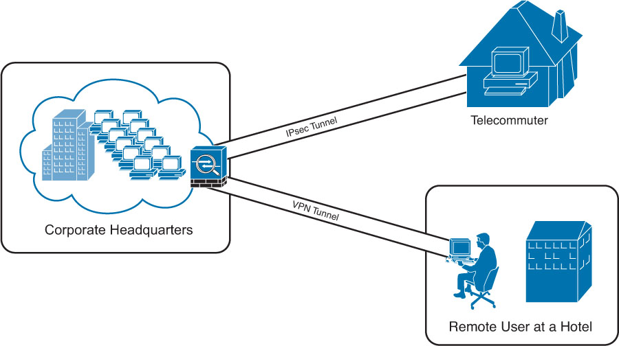
Figure 1-7 shows an example of remote-access VPN. In this case, a telecommuter employs IPsec VPN while a remote user from a hotel employs SSL VPN to connect to the corporate headquarters.
The following are the typical encryption algorithms:
![]() Data Encryption Standard (DES): 64 bits long
Data Encryption Standard (DES): 64 bits long
![]() Triple DES (3DES): 168 bits long
Triple DES (3DES): 168 bits long
![]() Advanced Encryption Standard (AES): 128 bits long
Advanced Encryption Standard (AES): 128 bits long
![]() AES 192: 192 bits long
AES 192: 192 bits long
![]() AES 256: 256 bits long
AES 256: 256 bits long
Hashing algorithms include
![]() Secure Hash Algorithm (SHA)
Secure Hash Algorithm (SHA)
![]() Message digest algorithm 5 (MD5)
Message digest algorithm 5 (MD5)
The common authentication methods are preshared keys (where peers use a shared secret to authenticate each other) and digital certificates with the use of Public Key Infrastructure (PKI).
Note
Typically, small and medium-sized organizations use preshared keys as their authentication mechanism. Several large organizations employ digital certificates for scalability, centralized management, and additional security mechanisms.
You can establish a Phase 1 SA in main mode or aggressive mode.
In main mode, the IPsec peers complete a six-packet exchange in three round trips to negotiate the ISAKMP SA, whereas aggressive mode completes the SA negotiation in three packet exchanges. Main mode provides identity protection if preshared keys are used. Aggressive mode offers identity protection only if digital certificates are employed.
Note
Cisco products that support IPsec typically use main mode for site-to-site tunnels and use aggressive mode for remote-access VPN tunnels. This is the default behavior when preshared keys are employed as the authentication method.
Figure 1-8 illustrates the six-packet exchange in main mode negotiation.
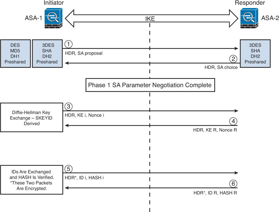
In Figure 1-8, two Cisco ASAs are configured to terminate a site-to-site VPN tunnel between them. The Cisco ASA labeled as ASA-1 is the initiator, and ASA-2 is the responder. The following steps are illustrated in Figure 1-8:
1. ASA-1 (the initiator) has two ISAKMP proposals configured. In the first packet, ASA-1 sends its configured proposals to ASA-2.
2. ASA-2 evaluates the received proposal. Because it has a proposal that matches the offer of the initiator, ASA-2 sends the accepted proposal back to ASA-1 in the second packet.
3. Diffie-Hellman exchange and calculation is started. Diffie-Hellman is a key agreement protocol that enables two users or devices to authenticate each other’s preshared keys without actually sending the keys over the unsecured medium. ASA-1 sends the Key Exchange (KE) payload and a randomly generated value called a nonce.
4. ASA-2 receives the information and reverses the equation, using the proposed Diffie-Hellman group/exchange to generate the SKEYID. The SKEYID is a string derived from secret material that is known only to the active participants in the exchange.
5. ASA-1 sends its identity information. The fifth packet is encrypted with the keying material derived from the SKEYID. The asterisk in Figure 1-8 is used to illustrate that this packet is encrypted.
6. ASA-2 validates the identity of ASA-1, and ASA-2 sends its own identity information to ASA-1. This packet is also encrypted.
Note
IKE uses UDP port 500 for communication. UDP port 500 is employed to send all the packets described in the previous steps.
IKEv1 Phase 2
Phase 2 is used to negotiate the IPsec SAs. This phase is also known as quick mode. The ISAKMP SA protects the IPsec SAs because all payloads are encrypted except the ISAKMP header.
A single IPsec SA negotiation always creates two security associations—one inbound and one outbound. Each SA is assigned a unique security parameter index (SPI) value—one by the initiator and the other by the responder.
Tip
The security protocols (AH and ESP) are Layer 3 protocols and do not have Layer 4 port information. If an IPsec peer is behind a PAT device, the ESP or AH packets are typically dropped. To work around this, many vendors, including Cisco Systems, use a feature called IPsec pass-through. The PAT device that is IPsec pass-through capable builds the Layer 4 translation table by looking at the SPI values on the packets.
Many industry vendors, including Cisco Systems, implement another feature called NAT Traversal (NAT-T). With NAT-T, the VPN peers dynamically discover whether an address translation device exists between them. If they detect a NAT/PAT device, they use UDP port 4500 to encapsulate the data packets, subsequently allowing the NAT device to successfully translate and forward the packets.
Another interesting point is that if the VPN router needs to connect multiple networks over the tunnel, it must negotiate twice as many IPsec SAs. Remember, each IPsec SA is unidirectional, so if three local subnets need to go over the VPN tunnel to talk to the remote network, then six IPsec SAs are negotiated. IPsec can use quick mode to negotiate these multiple Phase 2 SAs, using the single pre-established ISAKMP (IKEv1 Phase 1) SA. The number of IPsec SAs can be reduced, however, if source and/or destination networks are summarized.
Many different IPsec attributes are negotiated in quick mode, as shown in Table 1-2.
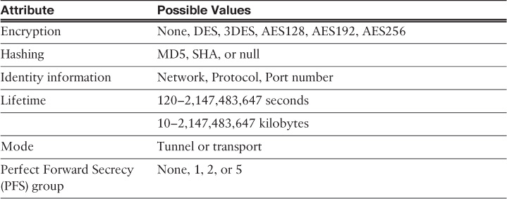
In addition to generating the keying material, quick mode also negotiates identity information. The Phase 2 identity information specifies which network, protocol, and/or port number to encrypt. Hence, the identities can vary anywhere from an entire network to a single host address, allowing a specific protocol and port.
Figure 1-9 illustrates the Phase 2 negotiation between the two routers that just completed Phase 1.
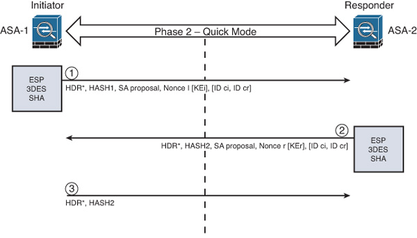
The following are the steps illustrated in Figure 1-9:
1. ASA-1 sends the identity information, IPsec SA proposal, nonce payload, and (optional) Key Exchange (KE) payload if Perfect Forward Secrecy (PFS) is used. PFS is employed to provide additional Diffie-Hellman calculations.
2. ASA-2 evaluates the received proposal against its configured proposal and sends the accepted proposal back to ASA-1, along with its identity information, nonce payload, and the optional KE payload.
3. ASA-1 evaluates the ASA-2 proposal and sends a confirmation that the IPsec SAs have been successfully negotiated. This starts the data encryption process.
IPsec uses two different protocols to encapsulate the data over a VPN tunnel:
![]() Encapsulation Security Payload (ESP): IP Protocol 50
Encapsulation Security Payload (ESP): IP Protocol 50
![]() Authentication Header (AH): IP Protocol 51
Authentication Header (AH): IP Protocol 51
Note
ESP is defined in RFC 4303, “IP Encapsulating Security Payload (ESP),” and AH is defined in RFC 4302, “IP Authentication Header.”
IPsec can use two modes with either AH or ESP:
![]() Transport mode: Protects upper-layer protocols, such as User Datagram Protocol (UDP) and TCP
Transport mode: Protects upper-layer protocols, such as User Datagram Protocol (UDP) and TCP
![]() Tunnel mode: Protects the entire IP packet
Tunnel mode: Protects the entire IP packet
Transport mode is used to encrypt and authenticate the data packets between the peers. A typical example is the use of GRE over an IPsec tunnel. Tunnel mode is employed to encrypt and authenticate the IP packets when they are originated by the hosts connected behind the VPN device. Tunnel mode adds an additional IP header to the packet, as illustrated in Figure 1-10.
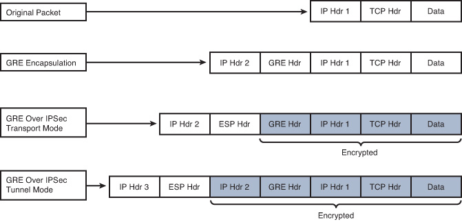
Figure 1-10 demonstrates the major difference between transport mode and tunnel mode. It includes an example of an IP packet encapsulated in GRE and the difference when it is encrypted in transport mode and tunnel mode. As demonstrated in Figure 1-10, tunnel mode increases the overall size of the packet in comparison to transport mode.
Note
Tunnel mode is the default mode in Cisco IPsec devices.
IKEv2
IKE version 2 (IKEv2) is defined in RFC 5996 and enhances the function of performing dynamic key exchange and peer authentication. IKEv2 simplifies the key exchange flows and introduces measures to fix vulnerabilities present in IKEv1. Both IKEv1 and IKEv2 protocols operate in two phases. IKEv2 provides a simpler and more efficient exchange.
Phase 1 in IKEv2 is IKE_SA, consisting of the message pair IKE_SA_INIT. IKE_SA is comparable to IKEv1 Phase 1. The attributes of the IKE_SA phase are defined in the Key Exchange Policy. Phase 2 in IKEv2 is CHILD_SA. The first CHILD_SA is the IKE_AUTH message pair. This phase is comparable to IKEv1 Phase 2. Additional CHILD_SA message pairs can be sent for rekey and informational messages. The CHILD_SA attributes are defined in the Data Policy.
The following differences exist between IKEv1 and IKEv2:
![]() IKEv1 Phase 1 has two possible exchanges: main mode and aggressive mode. There is a single exchange of a message pair for IKEv2 IKE_SA.
IKEv1 Phase 1 has two possible exchanges: main mode and aggressive mode. There is a single exchange of a message pair for IKEv2 IKE_SA.
![]() IKEv2 has a simple exchange of two message pairs for the CHILD_SA. IKEv1 uses an exchange of at least three message pairs for Phase 2.
IKEv2 has a simple exchange of two message pairs for the CHILD_SA. IKEv1 uses an exchange of at least three message pairs for Phase 2.
SSL VPNs
SSL-based VPNs leverage the SSL protocol. SSL, also referred to as Transport Layer Security (TLS), is a mature protocol that has been in existence since the early 1990s. The Internet Engineering Task Force (IETF) created TLS to consolidate the different SSL vendor versions into a common and open standard.
One of the most popular features of SSL VPN is the capability to launch a browser such as Google Chrome, Microsoft Internet Explorer, or Firefox and simply connect to the address of the VPN device, as opposed to running a separate VPN client program to establish an IPsec VPN connection. In most implementations, a clientless solution is possible. Users can access corporate intranet sites, portals, and email from almost anywhere (even from an airport kiosk). Because most people allow SSL (TCP port 443) over their firewalls, it is unnecessary to open additional ports.
The most successful application running on top of SSL is HTTP because of the huge popularity of the World Wide Web. All the most popular web browsers in use today support HTTPS (HTTP over SSL/TLS). This ubiquity, if used in remote-access VPNs, provides some appealing properties:
![]() Secure communication using cryptographic algorithms: HTTPS/TLS offers confidentiality, integrity, and authentication.
Secure communication using cryptographic algorithms: HTTPS/TLS offers confidentiality, integrity, and authentication.
![]() Ubiquity: The ubiquity of SSL/TLS makes it possible for VPN users to remotely access corporate resources from anywhere, using any PC, without having to preinstall a remote-access VPN client.
Ubiquity: The ubiquity of SSL/TLS makes it possible for VPN users to remotely access corporate resources from anywhere, using any PC, without having to preinstall a remote-access VPN client.
![]() Low management cost: The clientless access makes this type of remote-access VPN free of deployment costs and free of maintenance problems at the end-user side. This is a huge benefit for the IT management personnel, who would otherwise spend considerable resources to deploy and maintain their remote-access VPN solutions.
Low management cost: The clientless access makes this type of remote-access VPN free of deployment costs and free of maintenance problems at the end-user side. This is a huge benefit for the IT management personnel, who would otherwise spend considerable resources to deploy and maintain their remote-access VPN solutions.
![]() Effective operation with a firewall and NAT: SSL VPN operates on the same port as HTTPS (TCP/443). Most Internet firewalls, proxy servers, and NAT devices have been configured to correctly handle TCP/443 traffic. Consequently, there is no need for any special consideration to transport SSL VPN traffic over the networks. This has been viewed as a significant advantage over native IPsec VPN, which operates over IP protocol 50 (ESP) or 51 (AH), which in many cases needs special configuration on the firewall or NAT devices to let traffic pass through.
Effective operation with a firewall and NAT: SSL VPN operates on the same port as HTTPS (TCP/443). Most Internet firewalls, proxy servers, and NAT devices have been configured to correctly handle TCP/443 traffic. Consequently, there is no need for any special consideration to transport SSL VPN traffic over the networks. This has been viewed as a significant advantage over native IPsec VPN, which operates over IP protocol 50 (ESP) or 51 (AH), which in many cases needs special configuration on the firewall or NAT devices to let traffic pass through.
As SSL VPN evolves to fulfill another important requirement of remote-access VPNs, namely the requirement of supporting any application, some of these properties are no longer applicable, depending on which SSL VPN technology the VPN users choose. But overall, these properties are the main drivers for the popularity of SSL VPN in recent years and are heavily marketed by SSL VPN vendors as the main reasons for IPsec replacement.
Today’s SSL VPN technology uses SSL/TLS as secure transport and employs a heterogeneous collection of remote-access technologies such as reverse proxy, tunneling, and terminal services to provide users with different types of access methods that fit different environments. Subsequent chapters examine some commonly used SSL VPN technologies, such as:
![]() Reverse proxy technology
Reverse proxy technology
![]() Port-forwarding technology and Smart Tunnels
Port-forwarding technology and Smart Tunnels
![]() SSL VPN tunnel client (AnyConnect Secure Mobility Client)
SSL VPN tunnel client (AnyConnect Secure Mobility Client)
![]() Integrated terminal services
Integrated terminal services
HTTPS provides secure web communication between a browser and a web server that supports the HTTPS protocol. SSL VPN extends this model to allow VPN users to access corporate internal web applications and other corporate application servers that might or might not support HTTPS, or even HTTP. SSL VPN does this by using several techniques that are collectively called reverse proxy technology.
A reverse proxy is a proxy server that resides in front of the application servers, normally web servers, and functions as an entry point for Internet users who want to access the corporate internal web application resources. To the external clients, a reverse proxy server appears to be the true web server. Upon receiving the user’s web request, a reverse proxy relays the user request to the internal web server to fetch the content on behalf of the users and relays the web content to the user with or without additional modifications to the data being presented to the user.
Many web server implementations support reverse proxy. One example is the mod_proxy module in Apache. With so many implementations, you might wonder why you need an SSL VPN solution to have this functionality. The answer is that SSL VPN offers much more functionality than traditional reverse proxy technologies:
![]() SSL VPN can transform complicated web and some non-web applications that simple reverse proxy servers cannot handle. The content transformation process is sometimes called webification. For example, SSL VPN solutions enable users to access Windows or UNIX file systems. The SSL VPN gateway must be able to communicate with internal Windows or UNIX servers and webify the file access in a web browser–presentable format for the VPN users.
SSL VPN can transform complicated web and some non-web applications that simple reverse proxy servers cannot handle. The content transformation process is sometimes called webification. For example, SSL VPN solutions enable users to access Windows or UNIX file systems. The SSL VPN gateway must be able to communicate with internal Windows or UNIX servers and webify the file access in a web browser–presentable format for the VPN users.
![]() SSL VPN supports a wide range of business applications. For applications that cannot be webified, SSL VPN can use other resource access methods to support them. For users who demand ultimate access, SSL VPN provides network-layer access to directly connect a remote system to the corporate network, in the same manner as an IPsec VPN.
SSL VPN supports a wide range of business applications. For applications that cannot be webified, SSL VPN can use other resource access methods to support them. For users who demand ultimate access, SSL VPN provides network-layer access to directly connect a remote system to the corporate network, in the same manner as an IPsec VPN.
![]() SSL VPN provides a true remote-access VPN package, including user authentication, resource access privilege management, logging and accounting, endpoint security, and user experience.
SSL VPN provides a true remote-access VPN package, including user authentication, resource access privilege management, logging and accounting, endpoint security, and user experience.
The reverse proxy mode in SSL VPN is also known as clientless web access or clientless access because it does not require any client-side applications to be installed on the client machine. Client-based SSL VPN provides a solution where you can connect to the corporate network by just pointing your web browser to the Cisco ASA without the need of additional software being installed in your system.
Cisco AnyConnect Secure Mobility
There is a new wave of technological adoption and security threats: mobile devices that allow employees to work from anywhere at any time. Mobility is not completely new for enterprises. As discussed earlier in this chapter, remote-access and telecommuting solutions have existed for quite some time. However, the rapid proliferation of mobile devices increases on a daily basis. Every organization must embrace mobility to remain competitive and evolve to a new model of efficient workloads, especially because many organizations have spent millions of dollars enabling remote-access VPNs to their networks. Smartphones, tablets, and other mobile devices will surpass traditional PC-based devices in the very near future.
The Cisco AnyConnect Secure Mobility solution is designed to secure connections from these mobile devices. The combination of the Cisco AnyConnect Secure Mobility Client, the Cisco ASA, and web security enforcement with either Cisco IronPort Web Security Appliance or Cisco ScanSafe provides a complete, secure mobility solution.
The Cisco AnyConnect Secure Mobility Client is built on SSL VPN technology that enables security to the network behind the Cisco ASA and also provides corporate policy enablement when users are not connected to the corporate Cisco ASA. The Cisco AnyConnect Secure Mobility Client accomplishes this by leveraging ScanSafe technology to make sure that all web traffic traversing port 80 is inspected for malicious content. When connected to the Cisco ASA, the Cisco AnyConnect Secure Mobility Solution decides which applications and resources the user should access. This solution can be configured in such a way that a device will not be authenticated unless it complies with corporate policies and has up-to-date security in place.
Cisco customers have a choice to deploy a premises-based Cisco IronPort S-Series Web Security Appliance (WSA) or to use the Cisco ScanSafe Cloud Web Security (CWS) Software-as-a-Service (SaaS) solution to provide an end-to-end mobility security solution. The Cisco AnyConnect Secure Mobility Client has a telemetry module that it uses to send information about the source of malicious content to the Cisco WSA. The web filtering infrastructure employs this data to strengthen its web security scanning algorithms, improve the accuracy of the URL categories and web reputation database, and ultimately provide better URL filtering rules.
Cloud and Virtualization Security
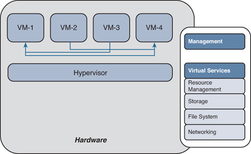
The adoption of cloud computing and virtualization is also changing the security landscape and driving the need for more advanced firewalls. The benefits of server virtualization are widely accepted, and numerous organizations have deployed these technologies. As organizations virtualize mission-critical systems, they must consider security and compliance implications. One of the challenges that virtualization introduces for traditional firewalls and security devices is that traffic between virtual machines (VM) often does not even leave the physical device. Consequently, a physical firewall, IPS device, or any other security appliance can’t be placed in between VMs to provide isolation, visibility, and control. In the example shown in Figure 1-11, four VMs reside on a physical server. Traffic between these VMs does not leave the physical server.
To address these challenges, Cisco created the Cisco ASA 1000V Cloud Firewall. It is an edge firewall virtual appliance that runs on VMware vSphere Hypervisor software and the Cisco Nexus 1000V Series Switch exclusively. The Cisco ASA 1000V Cloud Firewall allows VMs in a virtual data center to access the Internet and other areas of the corporate network securely (including inter-tenant communications), functions as the default gateway for the VMs, and protects against network-based attacks. The Cisco ASA 1000V Cloud Firewall complements the Cisco Virtual Security Gateway (VSG) context-aware security policies, supporting dynamic provisioning of security policies and trust zones during VM instantiation and movement.
Cisco Application Centric Infrastructure (ACI) integrates the Cisco ASA (physical and virtual) to deliver application centric security automation in the data center. This solution provides an innovative security service insertion framework to address the challenges of today’s threat landscape. The Cisco Application Policy Infrastructure Controller (APIC) is the central point of network service automation and policy control. It allows security professionals and network administrators to automate the configuration and provisioning of security services in application networks, by eliminating the complexity of traffic-steering techniques and the topology constraints of traditional networks.
The integration of the Cisco ACI solution with the Cisco ASA enables the automated security configuration, management, and security policy updates, for firewall, intrusion prevention, VPN services, and next-generation security services. This service policy automation is obtained through open RESTful APIs, with JSON and XML data formats.
Summary
Network security is a science that must be implemented carefully. There are many different techniques at the disposal of a network administrator to prevent attackers from gaining access to private networks and computer systems. This chapter provided an overview of the different technologies, principles, and protocols related to the integrated features of the Cisco ASA. The beginning of the chapter provided an overview of different firewall technologies and implementations, which was followed by the introduction of IDS and IPS solutions. The latter part of the chapter presented a detailed technical overview of site-to-site and remote-access VPN technologies. Additionally, an introduction to cloud and virtualization security was provided, covering next-generation concepts such as the Cisco ACI solution and framework.