
Chapter 17. Implementing Cisco ASA Intrusion Prevention System (IPS)
This chapter covers the following topics:
![]() Cisco IPS software architecture
Cisco IPS software architecture
![]() Preparing ASA IPS for configuration
Preparing ASA IPS for configuration
![]() Configuring CIPS software on ASA IPS
Configuring CIPS software on ASA IPS
![]() Configuring ASA for IPS traffic redirection
Configuring ASA for IPS traffic redirection
Cisco ASA integrates firewall capabilities with sophisticated intrusion prevention features that provide a comprehensive packet inspection solution. Hardware and software ASA IPS modules bring the complete Cisco Intrusion Prevention System feature set to effectively mitigate a wide range of network attacks without compromising ASA performance.
ASA IPS combines flexible signature-based policies with behavioral network traffic analysis to alleviate even the most complex and previously unknown attacks. Global correlation adds the ability to incorporate reputation information into the IPS policy decisions. The Botnet Traffic Filter feature operates independently on the ASA to complement the embedded ASA IPS functionality.
IPS Integration Overview
ASA appliances support integrated software and hardware modules that run Cisco Intrusion Prevention System (CIPS) software. One of the major features of CIPS is its capability to process and analyze traffic inline. This qualifies Cisco ASA to be classified as an IPS. The system image file and the feature set are similar to the ones that run on the dedicated Cisco IPS 4x00 Series Sensors, Cisco IDS Services Module-2 (IDSM-2) for Cisco Catalyst 6500, Cisco IPS Advanced Integration Module (IPS AIM), and Cisco IPS Network Module Enhanced (IPS NME) products. CIPS is different from the Next Generation (NG) IPS feature of the ASA CX module.
There are multiple available IPS solutions for different ASA models, as shown in Table 17-1.

ASA adds IPS protection to specified types of traffic by redirecting applicable connections to the module for external inspection. This redirection occurs as a step in the normal packet processing path, similarly to how ASA CX functions. CIPS processes all redirected traffic locally and has the ability to request the ASA to drop a particular packet or reset the connection. You must configure CIPS features and policies separately from the ASA, but Cisco Adaptive Security Device Manager (ASDM) has the ability to manage both products.
You can configure IPS inspection on ASA using the ips action within the Modular Policy Framework (MPF) by either defining specific traffic classes at Layer 3 and 4 or matching all transit traffic. Just as with ASA CX, IPS redirection matches on per-connection basis. ASA performs packet reordering on all TCP connections that are subject to IPS redirection. This capability allows this processor-intensive task to be offloaded from the IPS module and certain TCP normalization signatures to be relaxed. This behavior is different from that of ASA CX, which performs TCP reordering locally. Unlike CX, ASA IPS supports concurrent traffic inspection with all regular application inspection engines and other ASA features.
IPS Logical Architecture
Similarly to an ASA CX module, an ASA IPS module relies on several physical and virtual interfaces to communicate with the host ASA and external network:
![]() Internal-Control: ASA uses this interface for control communication with the IPS module. Module initialization, health monitoring keepalives, basic configuration, clock synchronization, and policy decision notification use this link. This interface also allows you to access the management interface of the IPS module from the ASA command line.
Internal-Control: ASA uses this interface for control communication with the IPS module. Module initialization, health monitoring keepalives, basic configuration, clock synchronization, and policy decision notification use this link. This interface also allows you to access the management interface of the IPS module from the ASA command line.
![]() Internal-Data: The IPS module receives redirected network traffic on this interface. ASA tags each redirected packet with a special header to provide additional metadata, such as NAT information. ASA also issues periodic keepalives on this link to monitor the operational status of the module.
Internal-Data: The IPS module receives redirected network traffic on this interface. ASA tags each redirected packet with a special header to provide additional metadata, such as NAT information. ASA also issues periodic keepalives on this link to monitor the operational status of the module.
![]() Management: CIPS also refers to this as the command and control interface. You must connect and configure this interface to manage the module from the network. Except on ASA 5505 appliances, the backplane connection does not provide external management access. CIPS also uses this interface to send SNMP traps and apply shuns to external devices. Unlike standalone IPS appliances, ASA IPS modules rely on the host ASA to generate TCP RST packets for offending connections.
Management: CIPS also refers to this as the command and control interface. You must connect and configure this interface to manage the module from the network. Except on ASA 5505 appliances, the backplane connection does not provide external management access. CIPS also uses this interface to send SNMP traps and apply shuns to external devices. Unlike standalone IPS appliances, ASA IPS modules rely on the host ASA to generate TCP RST packets for offending connections.
IPS Hardware Modules
Cisco ASA 5500 and ASA 5585-X appliances rely on external IPS hardware modules with their own storage, memory, and processing complexes. Such modules plug into an available expansion slot on the host chassis. The architecture of IPS modules on ASA 5585-X appliances is very similar to the architechture of ASA CX modules, but IPS SSP does not use the hard disk drives. The backplane connection with the chassis provides physical Internal-Data and Internal-Control interface connections. The line rate of the Internal-Data interface matches the forwarding capacity of the ASA and IPS platforms:
![]() 100 Mbps for ASA 5505 appliances
100 Mbps for ASA 5505 appliances
![]() 1 Gbps for ASA 5510, 5520, and 5540 appliances
1 Gbps for ASA 5510, 5520, and 5540 appliances
![]() 20 Gbps for ASA 5585-X appliances
20 Gbps for ASA 5585-X appliances
Internal-Control interfaces typically have less capacity because they have much lower bandwidth requirements. In some cases, they may share the same physical link with Internal-Data interfaces.
With the exception of AIP-SSC-5 in ASA 5505 appliances, all hardware IPS modules have dedicated external management interfaces. You must physically connect these interfaces to the network as you would any other endpoint or ASA CX. You cannot manage the ASA IPS module through any GUI product, such as Cisco ASDM or Cisco IPS Device Manager (IDM), without this connection. CIPS also relies on this command and control interface to automatically download software and signature updates and to communicate with the Cisco SensorBase network for the global correlation feature.
The ASA 5505 appliance allows you to extend a particular configured VLAN to the AIP-SSC-5 module for management connectivity through the backplane. Use the allow-ssc-mgmt interface configuration mode command under the desired VLAN on the ASA for this purpose. Configure CIPS with a management IP address on the same subnet as the corresponding ASA VLAN. If the management VLAN is isolated, the VLAN interface IP address on the ASA becomes the default gateway for the AIP-SSC-5 module. Otherwise, you can point the module to an external router on the management VLAN.
Keep in mind that regular ASA security policies still apply to IPS ASA command and control traffic when it traverses the firewall. Just as with CX, you must permit the appropriate management connections to and from the module as with any other transit network traffic.
IPS Software Modules
Similarly to ASA CX, ASA 5500-X appliances do not require an external module to implement IPS services. The necessary dedicated hardware for ASA IPS is already built into the device. When you need to implement IPS, simply activate the IPS Module license and install a CIPS software package on the ASA. Virtual Internal-Data and Internal-Control interfaces provide the link between IPS and ASA containers.
CIPS software runs in a separate container with dedicated memory and CPU cores, so it never competes for resources with the ASA software image. ASA 5525-X, 5545-X, and 5555-X appliances also provide ASA IPS with dedicated accelerator hardware for complex regex operations. Because ASA CX and IPS software modules use the same hardware, only one of these packages can currently operate on an ASA 5500-X at any given time. ASA IPS does not use the hard disk drives at this time.
A software IPS module also requires a physical management network connection. The Management0/0 interface on ASA 5500-X appliances internally extends to both the ASA and ASA IPS containers. Refer to the “Software Modules” section in Chapter 9, “Implementing Next-Generation Firewall Services with ASA CX,” for a detailed discussion on providing management connectivity to an ASA 5500-X software module. In summary, you have the following options:
![]() Connect Management0/0 to the dedicated management network
Connect Management0/0 to the dedicated management network
![]() Connect Management0/0 to a production network
Connect Management0/0 to a production network
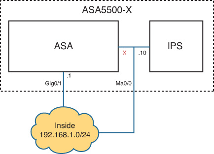
Figure 17-1 illustrates the second connectivity option. ASA IPS has the command and control IP address of 192.168.1.10 on the inside subnet. Management0/0 is enabled on the ASA but does not have the nameif command or an IP address. CIPS uses ASA inside IP address 192.168.1.1 as its default gateway to reach other internal networks and the Internet. This is very similar to how you would connect the management interface on a hardware IPS or CX module.
Inline and Promiscuous Modes
ASA supports both inline and promiscuous IPS modes. An inline ASA IPS module can drop malicious packets, generate alarms, or reset a connection, allowing the ASA to respond immediately to security threats and protect the network. All traffic matching the inline IPS redirection policy on the ASA must pass through the IPS module before leaving the device.
Figure 17-2 shows the traffic flow when an ASA IPS module is operating in inline mode.
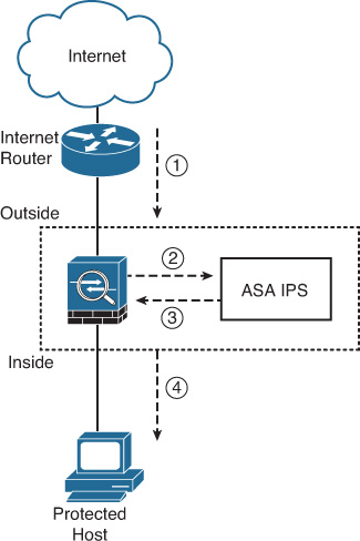
The following steps take place in Figure 17-2:
1. The ASA receives an IP packet from the Internet. The packet belongs to a connection that matches an inline IPS redirection policy on the ASA.
2. The ASA forwards the packet to the IPS module for analysis, assuming that the configured security policies allow this traffic into the protected network. If an interface or global ACL on the ASA denies this traffic, the packet never reaches the IPS module or the protected host.
3. The ASA IPS analyzes the packet and, if it determines that the packet is not malicious, instructs the ASA to pass this packet through.
4. The ASA forwards the packet to its final destination (the protected host).
When the IPS redirection policy uses promiscuous mode, ASA forwards only a copy of the packet to the IPS module for inspection. The packet itself advances to the internal network, depending on the configured security policies. Figure 17-3 shows the traffic flow when an ASA IPS is operating in promiscuous mode.
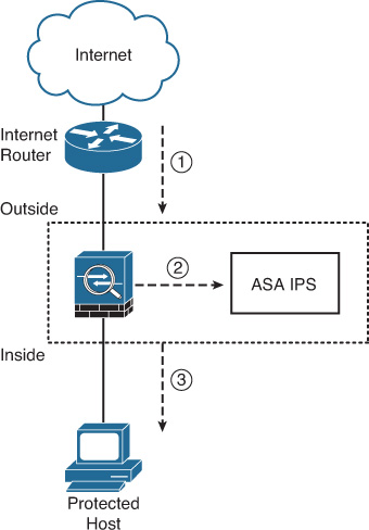
The following steps take place in Figure 17-3:
1. The ASA receives an IP packet from the Internet. The packet belongs to a connection that matches a promiscuous IPS redirection policy on the ASA.
2. The ASA sends a copy of the packet to the IPS module and immediately forwards it to the final destination (the protected host), assuming that the configured security policies allow this traffic into the protected network. If an interface or global ACL on the ASA denies this traffic, the packet never reaches the IPS module or the protected host.
3. The ASA IPS analyzes the copy of the packet and, if it determines that the packet is malicious, alerts the administrator or takes other configured action. The configuration of specific IPS security policies and the respective actions are covered later in this chapter in the “Configuring CIPS Software on ASA IPS” section. Because the malicious packet already reached the host, promiscuous IPS mode is not very effective against network attacks.
You would typically use promiscuous IPS mode to avoid extra latency or any other impact on critical transit traffic. Cisco ASA Software performs TCP packet reordering for all connections that match the IPS inspection policies, regardless of mode. The throughput of protected TCP connections may degrade even in promiscuous IPS mode if the associated packets consistently arrive out of order. This is a very rare occurrence and usually implies an upstream network problem.
IPS High Availability
ASA IPS modules operate similarly to ASA CX modules in terms of ASA failover interoperability. IPS also fully supports ASA clustering. An IPS module in each failover peer or cluster member does not exchange configuration or connection state information with other modules in the failover pair or the cluster. You must either configure all ASA IPS modules separately or leverage shared policies in Cisco Security Manager (CSM). Because ASA performs full TCP state tracking of all connections redirected to IPS, each local IPS module continues inspection of any flows that statefully fail over at the ASA level. Because failover and clustering do not preserve CIPS-specific data structures, IPS may not be able to detect certain complex, multistep attacks that were in progress at the time of the original ASA IPS failure.
As with ASA CX, you can create ASA IPS policies in fail-open or fail-close mode to determine transit traffic behavior on module failure. Refer to Chapter 9 for a detailed description of this functionality. If any configured policies involve IPS inspection, failover and clustering mark the ASA as failed if its IPS module is not ready to process this traffic. The configured fail-open or fail-close action executes if only one healthy failover peer or cluster member remains.
Both of these modes support inline and promiscuous IPS deployments. Even though an ASA IPS in promiscuous mode should not affect transit traffic, a fail-close policy blocks matching connections if the IPS module is unresponsive.
Cisco IPS Software Architecture
The CIPS software uses the Security Device Event Exchange (SDEE) protocol. SDEE is a standardized IPS communication protocol developed by Cisco for the IDS Consortium at the International Computer Security Association (ICSA). Remote applications such as ASDM, IDM, CSM, IPS Manager Express (IME), and Cisco Security Monitoring, Analysis, and Response System (CS-MARS) can retrieve events from the sensor through this protocol.
The major components of CIPS software include the following:
![]() Interprocess communication API (IDAPI)
Interprocess communication API (IDAPI)
![]() MainApp
MainApp
![]() SensorApp
SensorApp
![]() CollaborationApp
CollaborationApp
![]() EventStore
EventStore
![]() CLI
CLI
MainApp incorporates the following major subcomponents:
![]() AuthenticationApp
AuthenticationApp
![]() Attack Response Controller
Attack Response Controller
![]() cipsWebserver
cipsWebserver
![]() Logger
Logger
![]() CtlTransSource
CtlTransSource
![]() NotificationApp
NotificationApp
Figure 17-4 illustrates the main components of CIPS in correlation with ASA IPS.

MainApp
MainApp is responsible for several critical tasks in ASA IPS as well as all other platforms that support CIPS software. These tasks include the following:
![]() Initializing all CIPS components and applications
Initializing all CIPS components and applications
![]() Scheduling, downloading, and installing software updates
Scheduling, downloading, and installing software updates
![]() Configuring communication parameters
Configuring communication parameters
![]() Managing the system clock
Managing the system clock
![]() Gathering system statistics and software version information
Gathering system statistics and software version information
![]() Cleanly shutting down and restarting all CIPS services
Cleanly shutting down and restarting all CIPS services
The CIPS operating system initializes MainApp first so that it can start the CIPS applications in the following sequence:
1. Read and validate dynamic and static configurations.
2. Synchronize dynamic configuration data to system files.
3. Create EventStore and the Intrusion Detection Application Programming Interface (IDAPI) shared components.
4. Initialize status event subsystem.
5. Launch IPS applications as stated in the static configuration.
6. Wait until each application sends an initialization status event.
7. Generate an error event identifying all applications that did not start, if all status events are not received within 60 seconds.
8. Listen for control transaction requests and processes them accordingly.
MainApp controls the CIPS software installation and upgrades. It also manages network communication parameters, such as the following:
![]() ASA IPS hostname
ASA IPS hostname
![]() IP addressing and default gateway configuration for the IPS command and control interface
IP addressing and default gateway configuration for the IPS command and control interface
![]() Network access control list for management
Network access control list for management
AuthenticationApp
AuthenticationApp, as its name suggests, is the process that controls user authentication on ASA IPS or any other device running Cisco IPS 5.x and later software. Additionally, it administers all the user accounts, privileges, Secure Shell (SSH) keys, digital certificates, and authentication methods. AuthenticationApp controls authentication when the user connects via Telnet, SSH, a terminal session through ASA, ASDM, IDM, IME, or CSM.
Attack Response Controller
Attack Response Controller (formerly known as Network Access Controller [NAC]) is the application responsible for communicating with the ASA or any other supported device to shun (block) connections and attackers according to the configured IPS signature actions.
One of the functions of Attack Response Controller is to distribute shunning information to other IPS devices on the network to collectively control network access devices. IPS devices that perform this operation are referred to as master blocking sensors.
cipsWebserver
The CIPS web server (cipsWebserver) within ASA IPS enables configuration support for ASDM, IDM, IME, CSM, and other management products that rely on HTTP. It also provides support for SDEE transactions, such as the following:
![]() Reporting security events
Reporting security events
![]() Receiving Cisco Intrusion Detection Configuration (IDCONF) transactions
Receiving Cisco Intrusion Detection Configuration (IDCONF) transactions
![]() Processing IP logs
Processing IP logs
For instance, ASDM resides on and launches from Cisco ASA. However, it embeds an IDM instance that uses SDEE to communicate with the ASA IPS hosted by the CIPS web server. The CIPS web server supports HTTP 1.0 and 1.1 running Secure Sockets Layer (SSL) and Transport Layer Security (TLS).
Logger
ASA IPS logs alert, error, status, and debug messages as well as IP logs. These messages and IP logs are accessible through the CLI and SDEE clients such as IDM, CSM, and CS-MARS. Logger sends log messages with the following five levels of severity:
![]() Debug
Debug
![]() Timing
Timing
![]() Warning
Warning
![]() Error
Error
![]() Fatal
Fatal
CIPS stores these messages in the following file on the IPS module: /usr/cids/idsRoot/log/main.log.
To access this file, you must be logged in with the service account. The “User Account Administration” section later in this chapter provides instructions on how to create such an account. The content of this file also appears in the show tech-support CIPS command output. These messages are typically used by Cisco TAC engineers for troubleshooting purposes.
CIPS converts messages at warning level or above into evErrors and inserts them into the Event Store.
CtlTransSource
The internal application called CtlTransSource (formerly known as TransactionSource) handles SDEE and HTTP remote-control transactions. It manages all TLS communications with external management servers and monitoring systems, including basic authentication. When an application attempts a remote-control transaction, IDAPI redirects the transaction to CtlTransSource.
NotificationApp
CIPS supports a limited set of SNMP messages for IPS signature alerts and system notifications. NotificationApp monitors EventStore for new entries and generates applicable SNMP traps toward configured network management systems. You can configure CIPS with specific filters to narrow down the set of events that trigger traps.
NotificationApp also responds to SNMP polling requests for basic ASA IPS system information and high-level traffic statistics.
SensorApp
SensorApp is the application responsible for processing transit network traffic and examining it for any malicious content. ASA delivers redirected packets or their copies to CIPS through the Internal-Data backplane interface. CIPS abstracts the data plane on its side as a GigabitEthernet or TenGigabitEthernet interface, depending on the module type; these interface names do not indicate the actual throughput capability of the ASA IPS data plane.
If an ASA IPS policy operates in promiscuous mode, CIPS discards the associated packets after processing them by SensorApp, without any notification to the host ASA. When configured for inline operation, CIPS must request the host ASA to permit or deny every inspected packet.
SensorApp has two modules that are crucial for the operation of ASA IPS or any other device running CIPS software:
![]() Analysis Engine: This module can operate with multiple different CIPS policy sets. Each of these sets can apply separate signature definitions, anomaly detection profiles, and event action filter rules to defined classes of traffic. Such Analysis Engine instances are called virtual sensors. With the exception of AIP-SSC-5, all ASA IPS modules support up to four virtual sensors.
Analysis Engine: This module can operate with multiple different CIPS policy sets. Each of these sets can apply separate signature definitions, anomaly detection profiles, and event action filter rules to defined classes of traffic. Such Analysis Engine instances are called virtual sensors. With the exception of AIP-SSC-5, all ASA IPS modules support up to four virtual sensors.
![]() Alarm Channel: Each virtual sensor has a corresponding virtual alarm module that monitors events that are specific to this inspection instance and generates the applicable alerts. This module also allows you to apply specific event action filters for each virtual sensor.
Alarm Channel: Each virtual sensor has a corresponding virtual alarm module that monitors events that are specific to this inspection instance and generates the applicable alerts. This module also allows you to apply specific event action filters for each virtual sensor.
Keep in mind that all virtual sensor and alarm instances share the same EventStore.
CollaborationApp
In Cisco ASA Software version 7.0 and later, CIPS provides optional integration capabilities with the Cisco SensorBase network through global correlation. With this feature enabled, CIPS receives real-time information about malicious Internet hosts and networks. SensorApp uses this reputation data to influence its inspection decisions and apply preventive actions more aggressively toward known offenders. Traffic from certain hosts with very low reputation may be denied without spending additional processing resources on in-depth inspection. You can also configure CIPS to share some aggregated processing information with SensorBase and improve the accuracy of the data.
CollaborationApp is the module that handles communication with SensorBase network. It downloads the host reputation data and shares it with SensorApp. If you choose to participate in SensorBase, CollaborationApp receives applicable data from SensorApp and securely uploads it to Cisco.
EventStore
All IPS events are stored in EventStore with a time stamp and a unique ascending identifier. Additionally, CIPS internal applications write log, status, and error events into EventStore. SensorApp is the only entity that generates IPS alerts.
EventStore is designed to store CIPS events in a circular fashion. In other words, when it reaches the configured size, new events and log messages overwrite the oldest events. In CIPS code, the EventStore size is set to 30 MB for all platforms. You should always rely on IME or CSM for dependable external IPS event storage.
Preparing ASA IPS for Configuration
You must complete several tasks before you start to configure CIPS policies on ASA IPS:
![]() Install the CIPS image or re-image an existing ASA IPS
Install the CIPS image or re-image an existing ASA IPS
![]() Access CIPS CLI
Access CIPS CLI
![]() Configure basic management settings
Configure basic management settings
![]() Set up ASDM for IPS management
Set up ASDM for IPS management
![]() Install the appropriate CIPS license key
Install the appropriate CIPS license key
Installing CIPS System Software
All hardware ASA IPS modules come with preinstalled CIPS system software. You can re-image the module if you need to completely clear the current configuration or load a different software version. Keep in mind that you can perform CIPS software upgrades on ASA IPS without performing a complete re-image and losing the configuration.
To re-image a hardware ASA IPS module, you must download an appropriate system image file from Cisco.com. Make sure to pick the correct file for your ASA IPS model. After you download the desired system image file, follow these steps to complete the re-image process:
1. Place the system image file on a TFTP server that is accessible over the network. ASA IPS uses this server to download the system image file.
2. Connect the physical management interface of ASA IPS to the network. Even though you trigger the re-imaging process from the ASA, the IPS module performs the actual file download from the network. You can connect a host with the TFTP server directly to the management interface of ASA IPS.
3. Designate a management IP address for the ASA IPS. If the TFTP server is on a different subnet, you must also provide ASA IPS a default gateway to use for the download. If you place the TFTP server on the same subnet or connect it directly to the ASA IPS, point the default gateway to the TFTP server itself.
4. From the privileged exec mode on the host ASA, issue the following command and respond to the prompts:
asa# hw-module module 1 recover configure
Specify the full TFTP URL for the system image:
Image URL [tftp://0.0.0.0/]: tftp://172.16.164.124/IPS-SSM_20-K9-sys-1.1-a-7.1-7-E4.img
Provide the IP address for ASA IPS management interface:
Port IP Address [0.0.0.0]: 192.168.1.19
Optionally specify the VLAN identifier if the ASA IPS management interface is a trunk port. This is a very uncommon configuration, so you would typically leave it as 0:
VLAN ID [0]: 0
Provide the IP address of the ASA IPS default gateway or the TFTP server if directly connected:
Gateway IP Address [0.0.0.0]: 192.168.1.11
5. Start the re-imaging process with the hw-module module 1 recover boot command. When you issue this command, the IPS module reloads and attempts to retrieve the image from the specified TFTP server. Keep in mind that this process permanently deletes the previous CIPS image and all configuration information. You need to confirm this operation:
asa# hw-module module 1 recover boot
Module 1 will be recovered. This may erase all configuration and all data
on that device and attempt to download/install a new image for it. This may take several minutes.
Recover module 1? [confirm] y
Recover issued for module 1.
6. You can periodically issue the show module 1 detail command on the ASA to see if the ASA IPS is ready. You can also issue the debug module-boot 255 command on the ASA to monitor the progress of the re-imaging process in real time. Example 17-1 provides sample output of a successful re-image operation. Make sure to issue the no debug module-boot command after the process completes.
Example 17-1 ASA IPS Image Recovery Process Debug
Mod-1 148> Cisco Systems ROMMON Version (1.0(11)2) #0: Thu Jan 26 10:43:08 PST 2006
Mod-1 149> Platform ASA-SSM-20
Mod-1 150> GigabitEthernet0/0
Mod-1 151> Link is UP
Mod-1 152> MAC Address: 0019.e8d9.58f7
Mod-1 153> ROMMON Variable Settings:
Mod-1 154> ADDRESS=192.168.1.19
Mod-1 155> SERVER=172.16.164.124
Mod-1 156> GATEWAY=192.168.1.11
Mod-1 157> PORT=GigabitEthernet0/0
Mod-1 158> VLAN=untagged
Mod-1 159> IMAGE=IPS-SSM_20-K9-sys-1.1-a-7.1-7-E4.img
Mod-1 160> CONFIG=
Mod-1 161> LINKTIMEOUT=20
Mod-1 162> PKTTIMEOUT=4
Mod-1 163> RETRY=20
Mod-1 164> tftp [email protected] via 192.168.1.11
Mod-1 165> !!!!!!!!!!!!!!!!!!!!!!!!!!!!!!!!!!!!!!!!!!!!!!!!!!!!!!!!!!!!!!!!!!!!!!!!!!!!!!!!
[...]
Mod-1 284> !!!!!!!!!!!!!!!!!!!!!!!!!!!!!!!!!
Mod-1 285> Received 39131632 bytes
Mod-1 286> Launching TFTP Image...
Mod-1 287> Cisco Systems ROMMON Version (1.0(11)2) #0: Thu Jan 26 10:43:08 PST 2006
Mod-1 288> Platform ASA-SSM-20
Mod-1 289> Launching BootLoader...
You may have to install a software IPS module on ASA 5500-X appliances when adding IPS services to an existing device. Make sure to install an appropriate activation key for the IPS Module license first. Because the ASA IPS does not require additional hardware on this model, the re-imaging operation is a lot simpler by following these steps:
1. Download the appropriate ASA IPS system image file from Cisco.com and transfer it to the host ASA flash file system using TFTP, HTTP, HTTPS, FTP, or Samba. Make sure that you have enough free space in the ASA flash first.
2. Use the sw-module module ips recover configure command to point the ASA to the locally stored IPS system image file. For instance:
asa# sw-module module ips recover configure image disk0:IPS-SSP_5555-K9-sys-1.1-a-7.1-7-E4.aip
3. Issue the sw-module module ips recover boot command to start the re-imaging process. It happens similarly to hardware modules, but no network connection is required.
Accessing CIPS from the ASA CLI
After you install the appropriate CIPS system image on ASA IPS, you can access the CLI of the module over the ASA backplane by using the session 1 command on dedicated hardware modules and the session ips command on ASA 5500-X appliances. The default administrator username is cisco and the default password is cisco. You must change this password after the first login. There are four major user account roles that determine which operations a user can perform. Refer to the “User Account Administration” section of this chapter for more information on this topic. Example 17-2 shows user cisco successfully logging in to the CIPS CLI from the ASA command line.
Example 17-2 Logging in to ASA IPS CLI for the First Time
login: cisco
Password:
You are required to change your password immediately (password aged)
Changing password for cisco.
(current) password:
New password:
Retype new password:
***NOTICE***
This product contains cryptographic features and is subject to United States
and local country laws governing import, export, transfer and use. Delivery
of Cisco cryptographic products does not imply third-party authority to import,
export, distribute or use encryption. Importers, exporters, distributors and
users are responsible for compliance with U.S. and local country laws. By using
this product you agree to comply with applicable laws and regulations. If you
are unable to comply with U.S. and local laws, return this product immediately.
A summary of U.S. laws governing Cisco cryptographic products may be found at:
http://www.cisco.com/wwl/export/crypto/tool/stqrg.html
If you require further assistance please contact us by sending email to
[email protected].
***LICENSE NOTICE***
There is no license key installed on this IPS platform.
The system will continue to operate with the currently installed
signature set. A valid license must be obtained in order to apply
signature updates. Please go to http://www.cisco.com/go/license
to obtain a new license or install a license.
The CIPS CLI is similar to the Cisco ASA and IOS CLIs. It also has a configuration command mode that you enter by invoking the configure terminal command. As in Cisco IOS and ASA, you can display help for a specific command by typing a question mark (?) after the command. You can also type a question mark to view the valid keywords to complete the command. There are certain commands that generate interactive user prompts. An example of this is the setup command, which is covered in the following section.
Configuring Basic Management Settings
When you first log in to an ASA IPS that has not been configured before, the system automatically starts the initial configuration dialog:
--- Basic Setup ---
--- System Configuration Dialog ---
At any point you may enter a question mark '?' for help.
User ctrl-c to abort configuration dialog at any prompt.
Default settings are in square brackets '[]'.
Current time: Sun Oct 6 18:07:32 2013
Setup Configuration last modified: Sun Oct 06 18:01:28 2013
You can always re-run this interactive basic configuration process by issuing the setup command on the CIPS CLI. You can also configure these IPS settings through the Startup Wizard in ASDM, if desired. You must configure these settings before the IPS can communicate with any management station and start analyzing data from the network.
The CIPS CLI first displays the current configuration and then generates interactive prompts that guide you to complete the initial settings. The default input is shown inside square brackets, [ ]. To accept the default input, press Enter. You can follow these steps to configure basic ASA IPS settings over the CLI:
1. The configuration dialog asks you to enter the hostname for ASA IPS. The default hostname is sensor. Enter the new hostname (case sensitive) as follows:
Enter host name[sensor]: DC-IPS
2. You must enter the IP address and default gateway for the management interface of the ASA IPS. The default IP address is 192.168.1.2 and the default gateway is 192.168.1.1. Enter the IP address and gateway configuration in the following format:
<IP address>/<Subnet mask length in bits>,<Gateway IP address>
This example uses the management IP address of 192.168.1.19 with a 24-bit subnet mask (255.255.255.0) and the gateway of 192.168.1.11:
Enter IP interface[192.168.1.2/24,192.168.1.1]: 192.168.1.19/24,192.168.1.11
3. The configuration dialog prompts you to modify the current management access list. Type yes to add or delete hosts or networks that ASA IPS allows. By default, ASA IPS denies management sessions from all networks. You must change this access list to be able to manage ASA IPS remotely. Enter the access list entries in the following format:
<IP prefix>/<Prefix mask length in bits>
Press Enter when you are done adding management access list entries. 192.168.1.0/24 is the only allowed management network in this example:
Modify current access list?[no]: yes
Current access list entries:
No entries
Permit: 192.168.1.0/24
Permit:
4. The configuration dialog allows you to modify the DNS and HTTP Proxy settings for connecting to the SensorBase network for global correlation:
Use DNS server for Global Correlation?[no]: no
Use HTTP proxy server for Global Correlation?[no]: no
You can configure these setting later. Refer to the “Global Correlation” section later in this chapter for a detailed explanation of this feature.
5. You can also modify the system clock, time zone, and daylight saving time settings. Keep in mind that you need to specify the time zone offsets in minutes.
Modify system clock settings?[no]: yes
Modify summer time settings?[no]: yes
Use USA SummerTime Defaults?[yes]: yes
DST Zone[]: CDT
Offset[60]: 60
Modify system timezone?[no]: yes
Timezone[UTC]: CST
UTC Offset[0]: -360
ASA IPS synchronizes the clock with the host ASA chassis by default, but you can also configure a Network Time Protocol (NTP) server:
Use NTP?[no]: no
6. The system prompts you to enable the SensorBase network participation feature with global correlation. You can configure this setting later.
Participation in the SensorBase Network allows Cisco to collect aggregated statistics about traffic sent to your IPS.
SensorBase Network Participation level?[off]: off
7. CIPS displays the current configuration for your review and presents several options for the next step:
The following configuration was entered:
service host
network-settings
host-ip 192.168.1.19/24,192.168.1.11
host-name DC-IPS
telnet-option disabled
access-list 192.168.1.0/24
ftp-timeout 300
no login-banner-text
dns-primary-server disabled
dns-secondary-server disabled
dns-tertiary-server disabled
http-proxy no-proxy
exit
time-zone-settings
offset -360
standard-time-zone-name CST
exit
summertime-option recurring
offset 60
summertime-zone-name CDT
start-summertime
month march
week-of-month second
day-of-week sunday
time-of-day 02:00:00
exit
end-summertime
month november
week-of-month first
day-of-week sunday
time-of-day 02:00:00
exit
exit
ntp-option disabled
exit
service global-correlation
network-participation off
exit
[0] Go to the command prompt without saving this config.
[1] Return to setup without saving this config.
[2] Save this configuration and exit setup.
[3] Continue to Advanced setup.
You can discard the current configuration and abort the setup process or repeat the steps. You should save the current configuration if everything looks correct. You can configure the advanced CIPS settings through ASDM or IDM later.
8. If you choose to apply the current configuration, the CIPS software may need to reload to apply the new time zone settings:
Enter your selection[3]: 2
Warning: DNS or HTTP proxy is required for global correlation inspection and reputation filtering, but no DNS or proxy servers are defined.
Warning: Reboot is required before the configuration change will take effect
--- Configuration Saved ---
Complete the advanced setup using CLI or IDM.
To use IDM,point your web browser at https://<sensor-ip-address>.
Warning: The node must be rebooted for the changes to go into effect.
Continue with reboot? [yes]: yes
Broadcast Message from root@DC-IPS
(somewhere) at 14:28 ...
A system reboot has been requested. The reboot may not start for 90 seconds.
Command session with module ips terminated.
Remote card closed command session. Press any key to continue.
Setting Up ASDM for IPS Management
After you configure ASA IPS with the basic settings and connect its management interface to the network, you can fully manage the module through ASDM by navigating to Configuration > IPS. Initially, ASDM prompts you for the ASA IPS management access information, as shown in Figure 17-5. Keep in mind that ASDM establishes a separate network connection directly to the IPS module through its management interface. You must ensure that your management station has access to both ASA and ASA IPS over the network.
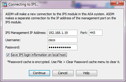
In Figure 17-5, ASA IPS uses the management IP address of 192.168.1.19. Complete the login credentials for the IPS administrative user and check the Save IPS Login Information on Local Host check box to avoid having to re-enter this information in the future.
Once connected, use the Configuration > IPS > Sensor Setup screens to change the basic settings of ASA IPS or even rerun the initial configuration dialog by clicking the Launch Startup Wizard button.
Installing the CIPS License Key
In addition to having the mandatory IPS Module license on ASA 5500-X appliances, all IPS modules require a valid CIPS license key for the following functionality:
![]() IPS signature package updates
IPS signature package updates
![]() Global correlation
Global correlation
An ASA IPS continues to inspect transit traffic with a non-existing or expired license, but your network will not be fully protected without the latest signatures. You should always install a CIPS license before configuring ASA IPS policies. Perform this task by navigating to Configuration > IPS > Sensor Management > Licensing in ASDM, as shown in Figure 17-6.

You have two options for applying the license:
![]() Automatically download it from Cisco.com: This option requires the IPS module to have a valid support contract for signature updates. You must also ensure that ASA IPS can reach the Internet from its management IP address on TCP ports 80 and 443.
Automatically download it from Cisco.com: This option requires the IPS module to have a valid support contract for signature updates. You must also ensure that ASA IPS can reach the Internet from its management IP address on TCP ports 80 and 443.
![]() Upload a license file: You can use the self-service Licensing tool on Cisco.com or request the file from the Licensing team at Cisco TAC. Make sure to provide the correct Product ID and Serial Number values as displayed on this screen.
Upload a license file: You can use the self-service Licensing tool on Cisco.com or request the file from the Licensing team at Cisco TAC. Make sure to provide the correct Product ID and Serial Number values as displayed on this screen.
Configuring CIPS Software on ASA IPS
The default configuration of an ASA IPS provides a comprehensive set of signatures and intelligent heuristic scanning features to deliver immediate protection of your network without an additional configuration effort. Unless you desire to configure advanced security features, such as anomaly detection or global correlation, you do not typically have to change any CIPS policies on ASA IPS. The only step you need to take upon deploying a brand new IPS module is to associate the default virtual sensor instance with the ASA backplane interface. After this is done, simply configure IPS traffic redirection policies on the ASA.
To design CIPS virtual sensors through ASDM, navigate to Configuration > IPS > Policies > IPS Policies. Select the default virtual sensor called vs0 in the list and click the Edit button. Figure 17-7 shows the Edit Virtual Sensor dialog box that opens to complete the configuration.
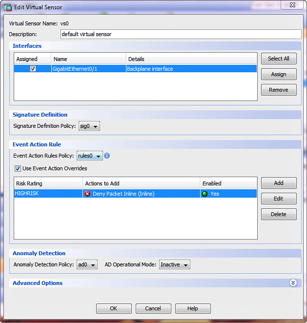
In the Interfaces area, check the Assigned check box for the Backplane Interface entry to apply IPS inspection to the traffic redirected from the ASA over the Internal-Data interface. Click OK to close the dialog box and then click Apply to push the configuration to the ASA IPS.
You can use this ASDM dialog box to configure up to three additional virtual sensors on all ASA IPS modules except AIP-SSC-5. Each virtual sensor can have a unique set of the following policies:
![]() Signature Definition Policy: You can enable or disable individual signatures in each policy and change individual signatures and their associated actions as well. This allows you to have a single ASA IPS apply different levels of inspection to separate groups of network traffic.
Signature Definition Policy: You can enable or disable individual signatures in each policy and change individual signatures and their associated actions as well. This allows you to have a single ASA IPS apply different levels of inspection to separate groups of network traffic.
![]() Event Action Rules Policy: You can add or remove signature actions based on specific attacker and victim IP addresses as well as the level of importance of each internal protected host. You can apply different actions to different classes of traffic with the same set of signatures.
Event Action Rules Policy: You can add or remove signature actions based on specific attacker and victim IP addresses as well as the level of importance of each internal protected host. You can apply different actions to different classes of traffic with the same set of signatures.
![]() Anomaly Detection Policy: You can build and monitor independent network traffic profiles for different categories of traffic.
Anomaly Detection Policy: You can build and monitor independent network traffic profiles for different categories of traffic.
You only need to assign the ASA IPS backplane interface to the default virtual sensor. All other virtual sensor instances automatically inherit this assignment. You can select which virtual sensor processes the traffic when configuring IPS traffic redirection on the ASA. Refer to the “Configuring ASA for IPS Traffic Redirection” section later in this chapter for more information.
Optionally, you can also configure the following advanced features of ASA IPS:
![]() Custom signatures
Custom signatures
![]() Remote blocking or shunning
Remote blocking or shunning
![]() Anomaly detection
Anomaly detection
![]() Global correlation
Global correlation
Custom Signatures
The capability to create custom signatures provides you with more flexibility in identifying security threats and network misconduct in a very effective fashion. This feature is available on all ASA IPS modules with the exception of AIP-SSC-5. To create custom signatures, you must know what exactly you want to detect in your network. This section demonstrates how to create a TCP custom signature. Figure 17-8 illustrates the attack vector.
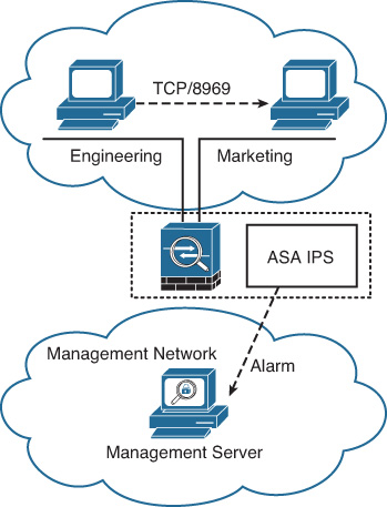
In this scenario, the security administrator knows that a new vulnerability exists whereby a machine can compromise other hosts and install malicious software while creating a TCP connection on port 8969. Unfortunately, other critical applications in the network use this port as well. The idea is to create a custom signature to detect this behavior from hosts that are not supposed to send any traffic on TCP port 8969, generate an alarm, and report this event to a management server. In Figure 17-8, a custom signature on the ASA IPS triggers an alarm if a host on the engineering segment attempts to establish a connection to a host on the marketing segment over TCP port 8969.
Take the following steps to configure this custom signature with ASDM:
1. Log in to ASDM and navigate to Configuration > IPS > Policies > Signature Definitions > sig0 > All Signatures.
2. Click Add to add a new signature. The Add Signature dialog box shown in Figure 17-9 opens.
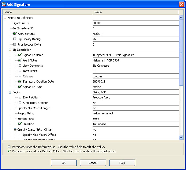
Configure the following parameters in the Add Signature dialog box (and leave the other parameters set to No):
![]() Signature ID: Enter a custom signature identifier value in the range of 60000 to 65000.
Signature ID: Enter a custom signature identifier value in the range of 60000 to 65000.
![]() SubSignature ID: Identify a more granular version of a broad signature. The value can be anything from 0 to 255. Figure 17-9 uses a value of 0, which is typical when one signature covers all known forms of this attack.
SubSignature ID: Identify a more granular version of a broad signature. The value can be anything from 0 to 255. Figure 17-9 uses a value of 0, which is typical when one signature covers all known forms of this attack.
![]() Alert Severity: Set to High, Informational, Medium, or Low.
Alert Severity: Set to High, Informational, Medium, or Low.
![]() Sig Fidelity Rating: Define how well this signature might perform in the absence of specific knowledge of the target. The value is 0 to 100. In this example, the default value of 75 is used.
Sig Fidelity Rating: Define how well this signature might perform in the absence of specific knowledge of the target. The value is 0 to 100. In this example, the default value of 75 is used.
![]() Promiscuous Delta: Define the seriousness of the alert. In this example, the default value of 0 is used.
Promiscuous Delta: Define the seriousness of the alert. In this example, the default value of 0 is used.
![]() Signature Name: Enter the name for the new custom signature.
Signature Name: Enter the name for the new custom signature.
![]() Alert Notes: Enter a note to be included within an alert produced by this signature. The alert note configured in Figure 17-9 is Malware in TCP 8969.
Alert Notes: Enter a note to be included within an alert produced by this signature. The alert note configured in Figure 17-9 is Malware in TCP 8969.
![]() User Comments: Add custom comments about this signature.
User Comments: Add custom comments about this signature.
![]() Release: Specify the software release in which the signature first appeared. In this case, the keyword custom is shown for a custom signature.
Release: Specify the software release in which the signature first appeared. In this case, the keyword custom is shown for a custom signature.
![]() Event Action: Configure the actions that the sensor takes when it responds to such an event. In this example, the default action of Produce Alert is configured.
Event Action: Configure the actions that the sensor takes when it responds to such an event. In this example, the default action of Produce Alert is configured.
![]() Regex String: Enter the regular expression string. In this example, the signature matches the malwareconnect string.
Regex String: Enter the regular expression string. In this example, the signature matches the malwareconnect string.
![]() Service Ports: Enter the service port(s). Port 8969 is used in this example.
Service Ports: Enter the service port(s). Port 8969 is used in this example.
![]() Direction: Configure the direction in which the ASA IPS will expect this malicious packet. In Figure 17-9, the direction is To Service.
Direction: Configure the direction in which the ASA IPS will expect this malicious packet. In Figure 17-9, the direction is To Service.
3. Click OK to close this dialog box and click Apply to push the new signature setting to the ASA IPS.
Remote Blocking
This section demonstrates how to configure the ASA IPS to interact with Cisco IOS routers, switches, PIX firewalls, and ASA products to block (shun) or rate-limit traffic from attacking IP addresses. This capability allows you to stop offending traffic at the network perimeter and save processing resources on the ASA IPS and other interior network devices.
It is important that you analyze your network topology to understand which attacking IP addresses ASA IPS can safely block and which IP addresses should be exempt from this action. Attackers may launch a DoS attack if they know about your shunning configuration. These DoS attacks can spoof legitimate source addresses, consequently causing disruption of legitimate hosts and services. You should implement the remote blocking feature very carefully and continuously tune it to avoid false positives.
ASA IPS and other Cisco IPS sensors can interact with Cisco IOS routers and Catalyst switches. The CIPS software can remotely apply ACLs in Cisco IOS routers or VLAN ACLs (VACL) in Catalyst switches to permit or deny incoming and outgoing traffic on their interfaces or VLANs. PIX firewalls and ASA devices do not use ACLs or VACLs; they instead rely on the shun command to implement basic filtering.
In Figure 17-10, the ASA IPS interacts with a Cisco IOS router at 10.10.12.254, which provides extranet connectivity on a dedicated link to a partner network. CIPS software automatically logs in to the router and blocks known attackers by applying an inbound ACL to the Ethernet0 interface.

The following steps demonstrate how to configure the ASA IPS through ASDM:
1. Configure a user profile to log in to the router by navigating to Configuration > IPS > Sensor Management > Blocking > Device Login Profiles and clicking Add. Figure 17-11 shows the Add Device Login Profile dialog box that opens.
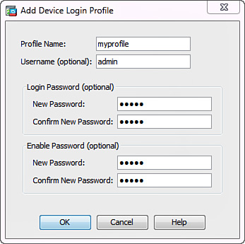
Complete the following fields and click OK:
![]() Profile Name: Create a name to reference this set of login credentials. Figure 17-11 uses myprofile as the profile name.
Profile Name: Create a name to reference this set of login credentials. Figure 17-11 uses myprofile as the profile name.
![]() Username: Specify a username for logging in to the remote device.
Username: Specify a username for logging in to the remote device.
![]() Login Password: Specify and confirm the password that corresponds to the username.
Login Password: Specify and confirm the password that corresponds to the username.
![]() Enable Password: Specify and confirm the enable password for this device.
Enable Password: Specify and confirm the enable password for this device.
2. Create a device entry for the router and associate it to the login profile by navigating to Configuration > IPS > Sensor Management > Blocking > Blocking Devices and clicking Add. Figure 17-12 shows the Add Blocking Device dialog box that opens.

Complete the following fields and click OK:
![]() IP Address: The IP address of the router to log in to. Figure 17-12 uses 10.10.12.254.
IP Address: The IP address of the router to log in to. Figure 17-12 uses 10.10.12.254.
![]() Sensor’s NAT Address: If the management IP address of the ASA IPS translates to a different IP address before reaching the router, specify this mapped NAT address here. In this example, there is no NAT in the path.
Sensor’s NAT Address: If the management IP address of the ASA IPS translates to a different IP address before reaching the router, specify this mapped NAT address here. In this example, there is no NAT in the path.
![]() Device Login Profile: Choose the configured profile with device login credentials. This example uses myprofile from Step 1.
Device Login Profile: Choose the configured profile with device login credentials. This example uses myprofile from Step 1.
![]() Device Type: Choose Cisco Router, Cat6K, or PIX ASA.
Device Type: Choose Cisco Router, Cat6K, or PIX ASA.
![]() Response Capabilities: Choose to Block or Rate Limit the offender. The Rate Limit action is only available for Cisco routers. ASA IPS applies an ACL to block the offender on the router.
Response Capabilities: Choose to Block or Rate Limit the offender. The Rate Limit action is only available for Cisco routers. ASA IPS applies an ACL to block the offender on the router.
![]() Communication: Choose between Telnet and SSH 3DES. Figure 17-12 uses SSH 3DES to access the router. For this method, you must also add the remote device’s public key to CIPS by navigating to Configuration > IPS > Sensor Management > SSH > Known Host Keys in ASDM, clicking Add, filling out the IP Address field, and clicking the Retrieve Host Key button to automatically populate the public key value.
Communication: Choose between Telnet and SSH 3DES. Figure 17-12 uses SSH 3DES to access the router. For this method, you must also add the remote device’s public key to CIPS by navigating to Configuration > IPS > Sensor Management > SSH > Known Host Keys in ASDM, clicking Add, filling out the IP Address field, and clicking the Retrieve Host Key button to automatically populate the public key value.
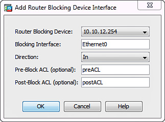
3. Specify the target interface name and direction of the ACL on the router by navigating to Configuration > IPS > Sensor Management > Blocking > Router Blocking Device Interfaces and clicking Add. Figure 17-13 shows the corresponding dialog box.
Complete the following fields and click OK:
![]() Router Blocking Device: Choose the configured blocking device to apply the interface configuration to. In Figure 17-13, 10.10.12.254 is used from Step 2.
Router Blocking Device: Choose the configured blocking device to apply the interface configuration to. In Figure 17-13, 10.10.12.254 is used from Step 2.
![]() Blocking Interface: Specify which interface on the router the ASA IPS will use to apply the blocking ACL. In Figure 17-13, the partner-facing Ethernet0 interface is chosen.
Blocking Interface: Specify which interface on the router the ASA IPS will use to apply the blocking ACL. In Figure 17-13, the partner-facing Ethernet0 interface is chosen.
![]() Direction: Apply the ACL in either In or Out direction on that interface. In this case, an inbound ACL is employed.
Direction: Apply the ACL in either In or Out direction on that interface. In this case, an inbound ACL is employed.
![]() Pre-Block ACL: Use a locally configured ACL on the router to always exclude certain traffic from blocking. This ACL typically contains the business-critical traffic.
Pre-Block ACL: Use a locally configured ACL on the router to always exclude certain traffic from blocking. This ACL typically contains the business-critical traffic.
![]() Post-Block ACL: Use a locally configured ACL on the router to append to the blocking ACL. You would typically reference a regular interface ACL that may already be configured on the router.
Post-Block ACL: Use a locally configured ACL on the router to append to the blocking ACL. You would typically reference a regular interface ACL that may already be configured on the router.
You can also configure some optional settings for remote blocking by navigating to Configuration > IPS > Sensor Management > Blocking > Blocking Properties in ASDM. Figure 17-14 shows an example of this screen.

The following parameters are available on this screen:
![]() Enable Blocking: Enable or disable the remote blocking feature. In Figure 17-14, the feature is enabled.
Enable Blocking: Enable or disable the remote blocking feature. In Figure 17-14, the feature is enabled.
![]() Allow Sensor IP Address to Be Blocked: If checked the management IP address of the ASA IPS can be included in the blocking ACL. It is highly unlikely that the ASA IPS will initiate an attack itself, so always keep this box unchecked.
Allow Sensor IP Address to Be Blocked: If checked the management IP address of the ASA IPS can be included in the blocking ACL. It is highly unlikely that the ASA IPS will initiate an attack itself, so always keep this box unchecked.
![]() Log All Block Events and Errors: If checked, event log entries are generated for all blocking actions. Keep this box checked, as shown in Figure 17-14.
Log All Block Events and Errors: If checked, event log entries are generated for all blocking actions. Keep this box checked, as shown in Figure 17-14.
![]() Enable NVRAM Write: If checked, as in Figure 17-14, the running configuration is saved to startup on remote blocking devices after applying the blocking or rate-limiting configuration.
Enable NVRAM Write: If checked, as in Figure 17-14, the running configuration is saved to startup on remote blocking devices after applying the blocking or rate-limiting configuration.
![]() Enable ACL Logging: If checked, a log option is added to the blocking ACLs on remote devices. Keep this option unchecked to save processing resources.
Enable ACL Logging: If checked, a log option is added to the blocking ACLs on remote devices. Keep this option unchecked to save processing resources.
![]() Maximum Block Entries: By default, an ASA IPS can maintain up to 250 active blocking entries. You can change this to any value between 1 and 65535.
Maximum Block Entries: By default, an ASA IPS can maintain up to 250 active blocking entries. You can change this to any value between 1 and 65535.
![]() Maximum Interfaces: By default, an ASA IPS supports up to 250 unique interfaces on remote blocking devices. You can change this to any value between 1 and 65535.
Maximum Interfaces: By default, an ASA IPS supports up to 250 unique interfaces on remote blocking devices. You can change this to any value between 1 and 65535.
![]() Maximum Rate Limit Entries: By default, an ASA IPS can maintain up to 250 active rate-limiting entries. You can change this to any value between 1 and 65535.
Maximum Rate Limit Entries: By default, an ASA IPS can maintain up to 250 active rate-limiting entries. You can change this to any value between 1 and 65535.
![]() Never Block Addresses: You can create a list of IP addresses and networks that the ASA IPS should never block. Figure 17-14 excludes subnet 192.168.10.0/24 and host 192.168.11.1 from all blocking actions.
Never Block Addresses: You can create a list of IP addresses and networks that the ASA IPS should never block. Figure 17-14 excludes subnet 192.168.10.0/24 and host 192.168.11.1 from all blocking actions.
Anomaly Detection
CIPS software includes limited network anomaly detection capabilities. This feature is available on all ASA IPS modules except AIP-SSC-5. This component of ASA IPS allows the module to reduce the dependency on signature updates for protection against previously unknown worms and malware. ASA IPS uses anomaly detection to learn normal network activity and send alerts or take dynamic response actions for behavior that deviates from the established baseline. This has enabled effective protection against many day-zero attacks.
Anomaly detection remains disabled by default to preserve ASA IPS processing resources. When you enable anomaly detection on ASA IPS, the feature conducts an initial learning process and then derives a set of policy thresholds that best fits the expected network traffic profile. This initial learning mode takes the default period of 24 hours. ASA IPS assumes that no attack occurs during this learning period. Anomaly detection creates an initial network traffic baseline, known as a knowledge base.
After the initial learning period, ASA IPS switches to the detection mode and actively compares transit traffic to the knowledge base and the allowed thresholds. By default, the module rotates the knowledge base every 24 hours to continuously update the network baseline as long as the traffic levels remain within the normal thresholds. Anomaly detection transitions into the inactive mode when you disable the feature on ASA IPS.
Anomaly detection maintains traffic profiles for three different zones, each of them conforming to separate thresholds. You must assign endpoint IP addresses, subnets, and ranges to these zones to minimize false positives and increase the efficiency of anomaly detection:
![]() Internal zone: This zone contains all of your inside protected networks. It is empty by default, so you must configure it manually.
Internal zone: This zone contains all of your inside protected networks. It is empty by default, so you must configure it manually.
![]() Illegal zone: This zone should contain IP addresses that ASA IPS should never see in transit traffic. These may include unassigned and reserved address spaces from your internal IP subnets. By setting very low thresholds for these unexpected IP addresses, anomaly detection can detect worms much quicker. This zone is also empty by default.
Illegal zone: This zone should contain IP addresses that ASA IPS should never see in transit traffic. These may include unassigned and reserved address spaces from your internal IP subnets. By setting very low thresholds for these unexpected IP addresses, anomaly detection can detect worms much quicker. This zone is also empty by default.
![]() External zone: This zone contains all IP addresses that do not belong to the internal or illegal zones. All endpoints belong to this zone by default.
External zone: This zone contains all IP addresses that do not belong to the internal or illegal zones. All endpoints belong to this zone by default.
Complete the following steps to configure anomaly detection on ASA IPS with ASDM:
1. Navigate to Configuration > IPS > Policies > Anomaly Detections. On this screen, you can add, clone, or delete an anomaly detection (AD) policy. The default AD policy is ad0. You would typically create multiple policies if you wanted to associate them with different virtual sensors. In this case, the default anomaly detection policy is used, so you should select ad0 as shown in Figure 17-15.
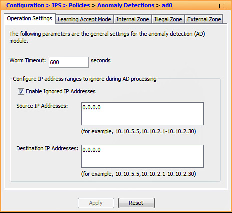
2. On the Operation Settings tab, the Worm Timeout field indicates how long anomaly detection should wait before resuming the continuous knowledge base update activity after an attack has been detected. Otherwise, the anomalous behavior may incorrectly influence the normal network baseline. The valid range is from 120 to 10,000,000 seconds. Figure 17-15 uses the default value of 600. You can also configure source and destination IP addresses that you want the sensor to ignore when AD is gathering information for a knowledge base. AD does not track these source and destination IP addresses, and the knowledge base thresholds are not affected by these IP addresses.
When desired, you can check the Enable Ignored IP Addresses check box and populate the Source IP Addresses and the Destination IP Addresses fields with respective addresses or address ranges that you want to exclude from traffic profiling. The default value of 0.0.0.0 implies that anomaly detection includes all IP addresses when learning and scanning transit traffic.
3. Click the Learning Accept Mode tab to determine how the sensor continuously updates the active knowledge base every specified time interval. The following options are available:
![]() Automatically Accept Learning Knowledge Base: When checked, ASA IPS continuously updates the knowledge base according to the current network activity. It is enabled by default.
Automatically Accept Learning Knowledge Base: When checked, ASA IPS continuously updates the knowledge base according to the current network activity. It is enabled by default.
![]() Action: You can choose Rotate to rotate the knowledge base and apply the new baseline profile on schedule. This is the default behavior. If you choose Save Only, anomaly detection saves the new traffic profile information but does not update the active knowledge base.
Action: You can choose Rotate to rotate the knowledge base and apply the new baseline profile on schedule. This is the default behavior. If you choose Save Only, anomaly detection saves the new traffic profile information but does not update the active knowledge base.
![]() Schedule: You can specify how often or when ASA IPS updates the traffic profile information and the associated active knowledge base in the Rotate mode. Choose either Calendar Schedule or Periodic Schedule.
Schedule: You can specify how often or when ASA IPS updates the traffic profile information and the associated active knowledge base in the Rotate mode. Choose either Calendar Schedule or Periodic Schedule.
4. Switch to the Internal Zone tab to configure IP addresses that belong to the internal zone. This tab has four additional tabs:
![]() General: Enable traffic profiling for the internal zone and specify its IP addresses, subnets, and ranges.
General: Enable traffic profiling for the internal zone and specify its IP addresses, subnets, and ranges.
![]() TCP Protocol: Enable TCP traffic profiling and configure specific thresholds and histograms. You would typically not change these settings.
TCP Protocol: Enable TCP traffic profiling and configure specific thresholds and histograms. You would typically not change these settings.
![]() UDP Protocol: Enable UDP traffic profiling and configure your own thresholds and histograms. You would typically not change these settings.
UDP Protocol: Enable UDP traffic profiling and configure your own thresholds and histograms. You would typically not change these settings.
![]() Other Protocols: Enable traffic profiling for other protocols and configure your own thresholds and histograms. You would typically not change these settings.
Other Protocols: Enable traffic profiling for other protocols and configure your own thresholds and histograms. You would typically not change these settings.
5. Switch to the Illegal Zone tab to configure IP addresses that belong to the illegal zone. This tab has the same additional tabs as the Internal Zone tab, with the exact settings.
6. Optionally, switch to the External Zone tab to enable or disable the external zone and configure protocol-specific thresholds similarly to the other zones. Because all addresses belong to the external zone by default, you do not need to explicitly configure anything here.
7. After applying the desired changes, navigate to Configuration > IPS > Policies > IPS Policies and click Edit for each virtual sensor that you would like to associate with an anomaly detection policy. Use the Anomaly Detection area of the Edit Virtual Sensor dialog box to set the following parameters:
![]() Anomaly Detection Policy: Choose the desired policy from the drop-down list. In this instance, keep the default setting of ad0.
Anomaly Detection Policy: Choose the desired policy from the drop-down list. In this instance, keep the default setting of ad0.
![]() AD Operational Mode: Choose Detect to enable the anomaly detection policy. If the knowledge base does not exist, the ASA IPS initially transitions to the learning mode for a period of 24 hours. You can choose Learn if you want to manually place the sensor into the learning mode; it will not automatically transition to the detection mode in this case. You can choose Inactive when you want to disable anomaly detection for the given virtual sensor.
AD Operational Mode: Choose Detect to enable the anomaly detection policy. If the knowledge base does not exist, the ASA IPS initially transitions to the learning mode for a period of 24 hours. You can choose Learn if you want to manually place the sensor into the learning mode; it will not automatically transition to the detection mode in this case. You can choose Inactive when you want to disable anomaly detection for the given virtual sensor.
The ASA IPS anomaly detection engine has nine signatures: one for every protocol in each supported zone. All signatures have two subsignatures: one for a scanner and the other for a worm-infected host. All of the anomaly detection signatures are enabled by default, but they do not produce any actions as long as the feature remains disabled. When an anomaly is detected with the feature enabled, ASA IPS triggers a high-severity alert for these signatures by default
The following are the supported actions for anomaly detection signatures:
![]() Produce alert
Produce alert
![]() Deny attacker inline (only in inline mode)
Deny attacker inline (only in inline mode)
![]() Log attacker packets
Log attacker packets
![]() Deny attacker service pair inline (only in inline mode)
Deny attacker service pair inline (only in inline mode)
![]() Request SNMP trap
Request SNMP trap
![]() Request block host
Request block host
Global Correlation
Global correlation allows ASA IPS to connect to the Cisco SensorBase network and use the downloaded endpoint reputation data during traffic analysis. If a particular Internet host engages in malicious activity, SensorBase distributes the offender’s IP address and reputation information to participating IPS sensors. If a sensor knows that the host participated in network attacks elsewhere, CIPS can look deeper into the associated traffic even if the behavior may otherwise appear benign. ASA IPS can even completely block certain connections if the source has a very low reputation score.
Global correlation is available on all ASA IPS modules with the exception of AIP-SSC-5. This feature is enabled by default, but you must configure a valid DNS server and ensure that the ASA IPS can access the Internet for global correlation updates to work. CIPS can also use an HTTP proxy server to retrieve the updates. You can configure these settings during the initial basic setup dialog or by navigating to the Configuration > IPS > Sensor Setup > Network screen in ASDM. Reputation updates happen every 5 minutes by default, but the update server may adjust this frequency automatically. Global correlation also requires ASA IPS to have a valid license.
To configure ASA IPS to use endpoint reputation data through global correlation, navigate to Configuration > IPS > Policies > Global Correlation > Inspection/Reputation in ASDM. Figure 17-16 illustrates a sample view of this panel. Global correlation settings apply to all virtual sensors.

Here you can configure the following options:
![]() Global Correlation Inspection: Choose On if you want ASA IPS to incorporate endpoint reputation data into the signature-based analysis. This does not mean that the module will always drop connections from Internet hosts that have low reputation scores. ASA IPS simply uses the reputation data as one variable in the complex contextual analysis of transit traffic. Choose Permissive, Standard, or Aggressive from the drop-down list to set the relative weight of the reputation component during risk level calculations for each signature. This option is enabled by default at the Standard level, as shown in Figure 17-16.
Global Correlation Inspection: Choose On if you want ASA IPS to incorporate endpoint reputation data into the signature-based analysis. This does not mean that the module will always drop connections from Internet hosts that have low reputation scores. ASA IPS simply uses the reputation data as one variable in the complex contextual analysis of transit traffic. Choose Permissive, Standard, or Aggressive from the drop-down list to set the relative weight of the reputation component during risk level calculations for each signature. This option is enabled by default at the Standard level, as shown in Figure 17-16.
![]() Reputation Filtering: Choose On if you want the IPS module to immediately block connections from known malicious hosts with very low reputation. Unlike signature-related events, CIPS does not record these drops in EventStore. This option is also enabled by default.
Reputation Filtering: Choose On if you want the IPS module to immediately block connections from known malicious hosts with very low reputation. Unlike signature-related events, CIPS does not record these drops in EventStore. This option is also enabled by default.
![]() Test Global Correlation: Check this box if you want to try global correlation without actually blocking any malicious transit traffic. ASA IPS still downloads the reputation information from the SensorBase network and logs events as if the feature was enabled. This option is disabled by default.
Test Global Correlation: Check this box if you want to try global correlation without actually blocking any malicious transit traffic. ASA IPS still downloads the reputation information from the SensorBase network and logs events as if the feature was enabled. This option is disabled by default.
In addition to receiving reputation updates from SensorBase, you can also configure ASA IPS to actively participate in this network by periodically uploading certain operational threat data. Cisco uses this information only for attack pattern analysis and never directly shares it with any third parties. You can enable the SensorBase network participation feature during the initial basic configuration dialog or by navigating to Configuration > IPS > Policies > Global Correlation > Network Participation, which gives you the following options:
![]() Off: ASA IPS never shares any operational data with SensorBase.
Off: ASA IPS never shares any operational data with SensorBase.
![]() Partial: ASA IPS shares only general, nonsensitive information.
Partial: ASA IPS shares only general, nonsensitive information.
![]() Full: ASA IPS can share additional data about specific targeted endpoints.
Full: ASA IPS can share additional data about specific targeted endpoints.
Network participation is disabled by default. If you choose Partial or Full on this screen and click Apply, you must click Agree or Disagree in a separate confirmation window, shown in Figure 17-17, that outlines the specific set of shared data for each of these two options.

Maintaining ASA IPS
This section includes information on administrative tasks that you can perform to maintain ASA IPS. These tasks include the following:
![]() Displaying CIPS software and process information
Displaying CIPS software and process information
![]() Upgrading CIPS software and signature packages
Upgrading CIPS software and signature packages
![]() Backing up ASA IPS configuration
Backing up ASA IPS configuration
![]() Displaying and clearing events
Displaying and clearing events
User Account Administration
You can configure ASA IPS with different types of users. Each ASA IPS user account has a role associated to it. A total of four roles can be assigned to a specific account:
![]() Administrator
Administrator
![]() Operator
Operator
![]() Viewer
Viewer
![]() Service
Service
Administrator Account
The administrator account has the highest privilege level. Users with this role can accomplish the following:
![]() Add and delete other users
Add and delete other users
![]() Assign user passwords
Assign user passwords
![]() Control all interfaces on ASA IPS
Control all interfaces on ASA IPS
![]() Configure IP addressing
Configure IP addressing
![]() Add and delete hosts allowed to connect to ASA IPS
Add and delete hosts allowed to connect to ASA IPS
![]() Tune signatures
Tune signatures
![]() Perform all virtual sensor configurations
Perform all virtual sensor configurations
![]() Configure shunning
Configure shunning
Operator Account
The operator account has the second highest privilege level. These users can view the configuration and statistics. They can also perform some limited administrative tasks such as modifying their own passwords, tuning signatures, and configuring shunning.
Viewer Account
Users with viewer privileges can only view events and some configuration files. They can also change their own passwords. The viewer account has the lowest of the privilege levels.
IPS monitoring applications require viewer access only to perform their monitoring operations. However, if the application is used to perform administrative tasks, a higher-privilege account is needed.
Service Account
The service account does not have direct access to the CIPS CLI. However, it has access to the backend bash shell, which enables service account users to perform advanced administrative tasks on the ASA IPS. This account is not enabled by default.
You can only configure one service account on ASA IPS and any other device running CIPS software. Only create the service account at the request of the Cisco Technical Assistance Center (TAC). Keep in mind that you can inadvertently damage your ASA IPS installation by performing certain operation from the service account. This condition may require you to re-image the ASA IPS to recover the module.
Adding, Changing, and Deleting Users
Navigate to Configuration > IPS > Sensor Setup > Authentication in ASDM to administer user accounts. You must have the administrator role to perform this operation. You can configure local user accounts or authenticate incoming management connections against an external RADIUS server.
Complete the following steps on this ASDM screen to add a user:
1. Click the Add button to bring up the Add User dialog box, shown in Figure 17-18.

2. Enter the desired username in the Username field. In Figure 17-18, viewuser is the username.
3. Choose the role in the User Role drop-down menu: Administrator, Operator, Service, or Viewer. The user will have Viewer privileges.
4. Enter and confirm the password for the new user in the Password area.
5. Click OK to add the user.
As an ASA IPS administrator, you can also click the Delete button to remove users or click the Edit button to change their parameters, including the assigned role and password.
Displaying CIPS Software and Process Information
Use the show version command to display the versions of CIPS software, signature packages, and IPS processes running on the ASA IPS. Example 17-3 shows sample output of this command on an ASA-SSM-20.
Example 17-3 CIPS Version and Process Information
DC-IPS# show version
Application Partition:
Cisco Intrusion Prevention System, Version 7.1(7)E4
Host:
Realm Keys key1.0
Signature Definition:
Signature Update S691.0 2013-01-22
OS Version: 2.6.29.1
Platform: ASA-SSM-20
Serial Number: JAF11063358
No license present
Sensor up-time is 3:23.
Using 1046M out of 1982M bytes of available memory (52% usage)
system is using 29.0M out of 160.0M bytes of available disk space (18% usage)
application-data is using 61.9M out of 169.5M bytes of available disk space (38% usage)
boot is using 54.7M out of 69.7M bytes of available disk space (83% usage)
application-log is using 123.5M out of 513.0M bytes of available disk space (24% usage)
MainApp S-2013_FEB_05_05_37_7_1_6_65 (Release) 2013-02-05T05:40:22-0600 Running
AnalysisEngine S-2013_FEB_05_05_37_7_1_6_65 (Release) 2013-02-05T05:40:22-0600 Running
CollaborationApp S-2013_FEB_05_05_37_7_1_6_65 (Release) 2013-02-05T05:40:22-0600 Running
CLI S-2013_FEB_05_05_37_7_1_6_65 (Release) 2013-02-05T05:40:22-0600
Upgrade History:
IPS-K9-7.1-7-E4 20:50:07 UTC Wed Feb 13 2013
Recovery Partition Version 1.1 - 7.1(7)E4
Host Certificate Valid from: 05-Oct-2013 to 06-Oct-2015
The first shaded line in Example 17-3 shows the CIPS software version running on the ASA IPS. The second shaded line indicates that the IPS module has been up for 3 hours and 23 minutes. The third shaded line shows information about previous CIPS software upgrades on this module; in this case, this is the first image that the ASA IPS had installed. The output includes other useful information, such as disk and memory utilization and the operational state of the various CIPS processes.
To monitor ASA IPS system information with ASDM, navigate to Home and click the Intrusion Prevention tab. This screen offers various gadgets that help you monitor different aspects of the IPS module. Each gadget displays the time of the last information update. The following gadgets are available:
![]() Sensor Information: Lists the CIPS software version, management IP address, module type, and other similar information.
Sensor Information: Lists the CIPS software version, management IP address, module type, and other similar information.
![]() Sensor Health: Shows high-level sensor and network security health information. Click the Details link to display specific information about individual items.
Sensor Health: Shows high-level sensor and network security health information. Click the Details link to display specific information about individual items.
![]() Licensing: Includes the status of the CIPS license key, signature updates, and signature engine updates.
Licensing: Includes the status of the CIPS license key, signature updates, and signature engine updates.
![]() Interface Status: Displays information about the management and backplane interfaces of ASA IPS.
Interface Status: Displays information about the management and backplane interfaces of ASA IPS.
![]() Global Correlation Reports: Shows statistics for malicious packets denied by global correlation.
Global Correlation Reports: Shows statistics for malicious packets denied by global correlation.
![]() Global Correlation Health: Displays the status of the network connection to SenderBase and the last database update timestamp.
Global Correlation Health: Displays the status of the network connection to SenderBase and the last database update timestamp.
![]() Network Security: Shows alert counts along with the average and maximum threat and risk ratings.
Network Security: Shows alert counts along with the average and maximum threat and risk ratings.
![]() Top Applications: Displays the top ten applications that ASA IPS has discovered.
Top Applications: Displays the top ten applications that ASA IPS has discovered.
![]() CPU, Memory, & Load: Shows the sensor load, CPU, memory, and disk usage for the ASA IPS.
CPU, Memory, & Load: Shows the sensor load, CPU, memory, and disk usage for the ASA IPS.
Upgrading CIPS Software and Signatures
You can apply the CIPS software service packs and signature updates using any of the following supported protocols and methods:
![]() File Transfer Protocol (FTP)
File Transfer Protocol (FTP)
![]() Hypertext Transfer Protocol (HTTP)
Hypertext Transfer Protocol (HTTP)
![]() Hypertext Transfer Protocol Secure (HTTPS)
Hypertext Transfer Protocol Secure (HTTPS)
![]() Secure Copy Protocol (SCP)
Secure Copy Protocol (SCP)
![]() Manual file upload through ASDM or IDM
Manual file upload through ASDM or IDM
![]() IPS Update Server in CSM
IPS Update Server in CSM
If you use HTTPS, a trusted TLS host entry must be added for the server from which you will retrieve the service pack or signature update file. You can add such an entry by navigating to Configuration > IPS > Sensor Management > Certificates > Trusted Hosts in ASDM.
You can perform one-time upgrades or schedule recurring automatic upgrades. You can only use automatic upgrades for service packs and signature packages. You must use the manual one-time upgrade process for major CIPS software updates. Signature updates require the ASA IPS to have a valid CIPS license.
One-Time Upgrades
To use ASDM to manually upgrade CIPS software on an ASA IPS, navigate to Configuration > IPS > Sensor Management > Update Sensor. Figure 17-19 shows this ASDM screen.

Figure 17-19 uses FTP to download the signature update package. The URL for the package is ftp://192.168.10.34/upgrade/upgrade_file.pkg, and the FTP username is ftpuser.
You can use the upgrade source-url command to apply CIPS updates and signature packages to the ASA IPS over CLI instead of ASDM. The following is the command syntax for source-url:
<Protocol>://<Username>@<IP Address or FQDN>/<Directory path>/<Filename>
When you specify a username, CIPS prompts you for the corresponding password as well. If you enter just the upgrade command followed by a protocol prefix (ftp:, http:, https:, or scp:), you can follow the interactive prompts to input the rest of the information.
In Example 17-4, CIPS retrieves the signature update package from an HTTPS server at 192.168.10.34. Keep in mind that you must enter this server IP address into the TLS trusted list first. The connection relies on user httpsuser for authentication purposes. After invoking the command, the ASA IPS prompts you to enter the password for this user.
Example 17-4 Applying Signature Updates
DC-IPS# configure terminal
DC-IPS(config)# upgrade https://[email protected]/upgrade/sigupdate.pkg
Enter password: *****
Scheduled Upgrades
As a best practice, configure automatic service pack and signature package updates. This simplifies module administration and provides a mechanism to make sure that your ASA IPS is always running with an up-to-date set of signatures.
You can enable automatic updates from a particular local server using all of the previously described protocols. You can also configure the ASA IPS to automatically download signature update packages from Cisco.com if you have the appropriate support contract. You would typically use the former method to control the distribution of IPS signature updates and test them before deploying to production IPS devices.
In Figure 17-20, the goal is to configure the ASA IPS module to automatically retrieve CIPS and signature update packages from a local SCP server every Monday, Wednesday, and Friday at 1:00 a.m.

Configure scheduled upgrades in ASDM by navigating to Configuration > IPS > Sensor Management > Auto/Cisco.com Update, as shown in Figure 17-21. Use the Remote Server Settings area to configure scheduled upgrades from a local server. Use the Cisco.com Server Setting area to configure automatic signature updates from Cisco.com if you have the appropriate support contract for the ASA IPS.
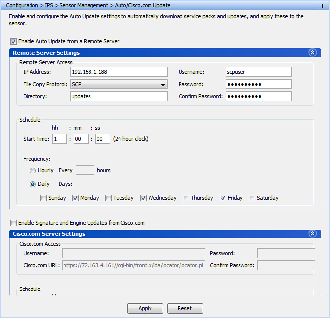
Take the following steps on this ASDM screen to configure scheduled ASA IPS upgrades from a local server as shown in Figure 17-21:
1. Check the Enable Auto Update from a Remote Server check box.
2. Enter the IP address of the remote server in the IP Address field. The server’s IP address in this case is 192.168.1.188.
3. Choose the transfer protocol from the File Copy Protocol drop-down menu. SCP is used in Figure 17-21.
4. In the Directory field, enter the directory where the updates will be stored on the remote server. The directory in this example is called updates.
5. In the Username and Password fields, enter the username and password of the remote server user. The username is scpuser in Figure 17-21.
6. Configure the start time and frequency for the automatic updates in the Schedule area. In this example, the ASA IPS automatically retrieves CIPS software and signature updates every Monday, Wednesday, and Friday at 1:00 a.m.
Backing Up ASA IPS Configuration
Back up your ASA IPS configuration on a regular basis. Use the local flash storage on the ASA IPS or a remote server for this purpose.
Use the copy current-config backup-config command to make a backup of the current configuration to a file (called backup-config) locally stored on the ASA IPS. You can merge the backup configuration file with the current configuration file or overwrite the current configuration file with the backup configuration file. In this example, the ASA IPS merges the backup configuration file with the current configuration:
DC-IPS# copy backup-config current-config
In this example, the ASA IPS overwrites the current configuration with the content of the backup configuration file:
DC-IPS# copy /erase backup-config current-config
For maximum protection, back up the ASA IPS configuration file to an external server. In Example 17-5, the IPS module copies a backup of its configuration file to an FTP server at 192.168.10.159.
Example 17-5 Backing Up CIPS Configuration to FTP Server
DC-IPS# copy current-config ftp://192.168.10.159
User: ftpuser
File name: DC_IPS_Config.cfg
Password: ********
Displaying and Clearing Events
To show IPS events using ASDM, navigate to the Monitoring > IPS > Sensor Monitoring > Events screen, as shown in Figure 17-22.
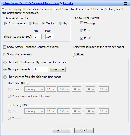
The following fields are available on this screen:
![]() Show Alert Events: Determine the level of alerts to display (Informational, Low, Medium, or High). By default, all levels are enabled.
Show Alert Events: Determine the level of alerts to display (Informational, Low, Medium, or High). By default, all levels are enabled.
![]() Threat Rating (0-100): Narrow the range (minimum and maximum levels) of the threat rating values.
Threat Rating (0-100): Narrow the range (minimum and maximum levels) of the threat rating values.
![]() Show Error Events: Configure the type of errors to display (Warning, Error, or Fatal). By default, only Error and Fatal events are displayed.
Show Error Events: Configure the type of errors to display (Warning, Error, or Fatal). By default, only Error and Fatal events are displayed.
![]() Show Attack Response Controller Events: Check this check box to include actions taken by the Attack Response Controller module. It is unchecked by default.
Show Attack Response Controller Events: Check this check box to include actions taken by the Attack Response Controller module. It is unchecked by default.
![]() Show Status Events: Check this check box to include CIPS status events. It is unchecked by default.
Show Status Events: Check this check box to include CIPS status events. It is unchecked by default.
![]() Select the Number of the Rows per Page: Configure how many rows of IPS events show up per page. The valid range is 100 to 500, and the default value is 100.
Select the Number of the Rows per Page: Configure how many rows of IPS events show up per page. The valid range is 100 to 500, and the default value is 100.
![]() Show All Events Currently Stored on the Sensor: Click this radio button to retrieve all events stored on the ASA IPS.
Show All Events Currently Stored on the Sensor: Click this radio button to retrieve all events stored on the ASA IPS.
![]() Show Past Events: Click this radio button to retrieve only the recent events. You can specify the specific interval in hours or minutes. The default interval is 1 hour.
Show Past Events: Click this radio button to retrieve only the recent events. You can specify the specific interval in hours or minutes. The default interval is 1 hour.
![]() Show Events from the Following Time Range: Click this radio button to retrieve events from within the time range that you specify.
Show Events from the Following Time Range: Click this radio button to retrieve events from within the time range that you specify.
Click View to display the events based on the previously configured options. Clicking the Reset button restores all options to the default values.
Clear the local EventStore by issuing the clear events CLI command on ASA IPS, as demonstrated in Example 17-6. CIPS displays a warning message asking you to confirm the removal of all the events stored on the system. These events are permanently lost if they have not been previously retrieved by a management or monitoring device.
Example 17-6 Clearing IPS EventStore
DC-IPS# clear events
Warning: Executing this command will remove all events currently stored in the event store.
Continue with clear? []: yes
Configuring ASA for IPS Traffic Redirection
After configuring IPS settings and security policies in CIPS software, you can redirect transit connections from ASA to the IPS module. On the ASA side, you would configure IPS traffic redirection similarly to application inspection or advanced connection settings through the MPF. Refer to Chapter 13, “Application Inspection,” for a detailed discussion on how to configure and use MPF traffic classes, policies, and actions.
Use ASDM to configure IPS traffic redirection by navigating to Configuration > Firewall > Service Policy Rules. To enable IPS redirection on an existing class of traffic, select an existing rule from the list, click Edit, and click the Intrusion Prevention tab, as shown in Figure 17-23.
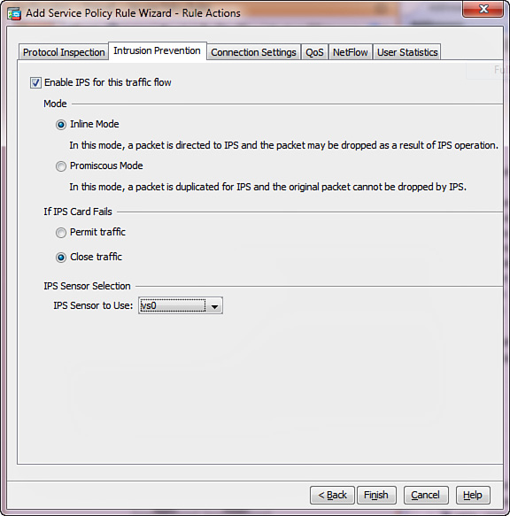
The process used to apply IPS services to a new traffic class is illustrated in the following steps:
1. Choose Add >Add Service Policy Rule to launch the Add Service Policy Rule Wizard.
2. On the wizard’s Service Policy page, choose which MPF policy to use. You can either construct an interface policy (click the Interface radio button) or use the global one. Click Global – Applies to All Interfaces to leverage the global policy. This allows you to pick up traffic for IPS redirection from all configured data interfaces. Click Next.
3. On the Traffic Classification Criteria page, define a class of traffic for IPS redirection. You can create a new class or use an existing one; you can create multiple classes if you want to mix inline and promiscuous redirection policies or leverage different virtual sensors on ASA IPS. If you choose the Create a New Traffic Class radio button, you can then choose the desired traffic matching criteria as well by checking boxes in the Traffic Match Criteria area. You would typically check Source and Destination IP Address (Uses ACL) when creating multiple IPS policies, to achieve the maximum flexibility. For purposes of this example, the Any Traffic check box is checked to match any traffic for a single ASA IPS policy under a class called global-class; this choice covers all transit IPv4 and IPv6 connections. Click Next.
4. On the Rule Actions page, click the Intrusion Prevention tab, as shown in Figure 17-23.
You can select the following options:
![]() Enable IPS for This Traffic Flow: Check this box to redirect the selected class of traffic to ASA IPS for inspection.
Enable IPS for This Traffic Flow: Check this box to redirect the selected class of traffic to ASA IPS for inspection.
![]() Mode: Choose between Inline Mode and Promiscuous Mode. Refer to the “Inline and Promiscuous Modes” section earlier in this chapter for more information. You can select different modes for various classes of traffic with a single ASA IPS module. Inline Mode is chosen in Figure 17-23.
Mode: Choose between Inline Mode and Promiscuous Mode. Refer to the “Inline and Promiscuous Modes” section earlier in this chapter for more information. You can select different modes for various classes of traffic with a single ASA IPS module. Inline Mode is chosen in Figure 17-23.
![]() If IPS Card Fails: Choose Permit Traffic to bypass IPS redirection if the ASA IPS is not ready (fail-open). Choose Close Traffic to deny any transit connections that match the IPS redirection policy if the module is not ready (fail-close). Refer to the “IPS High Availability” section earlier in this chapter for additional information. In Figure 17-23, the fail-close mode is used.
If IPS Card Fails: Choose Permit Traffic to bypass IPS redirection if the ASA IPS is not ready (fail-open). Choose Close Traffic to deny any transit connections that match the IPS redirection policy if the module is not ready (fail-close). Refer to the “IPS High Availability” section earlier in this chapter for additional information. In Figure 17-23, the fail-close mode is used.
![]() IPS Sensor Selection: When available, choose which ASA IPS virtual sensor you want to inspect this traffic. You can choose Default Sensor or a specific name. Refer to the “Configuring CIPS Software on ASA IPS” section earlier in this chapter for additional information about virtual sensors. You can also allocate particular virtual sensors to different ASA contexts when operating in the multiple-context mode. In this example, vs0 is used as the target virtual sensor.
IPS Sensor Selection: When available, choose which ASA IPS virtual sensor you want to inspect this traffic. You can choose Default Sensor or a specific name. Refer to the “Configuring CIPS Software on ASA IPS” section earlier in this chapter for additional information about virtual sensors. You can also allocate particular virtual sensors to different ASA contexts when operating in the multiple-context mode. In this example, vs0 is used as the target virtual sensor.
5. Click Finish to close the wizard and click Apply to push the configuration to the ASA.
Example 17-7 shows the respective configuration that ASDM sends to the ASA for the previous example.
Example 17-7 Sample IPS Redirection Policy
class-map global-class
match any
!
policy-map global_policy
class global-class
ips inline fail-close sensor vs0
Botnet Traffic Filter
Botnet Traffic Filter (BTF) leverages cloud technology to identify and block potential botnet traffic through the ASA. A botnet is a group of Internet robots (“bots”) that runs malicious software, often operated by different criminal entities. Although this is not an ASA IPS feature, BTF complements IPS global correlation by detecting transit connections from and to known malware and botnet control sites at the ASA level. BTF requires a time-based Botnet Traffic Filter license on the ASA (see Chapter 3, “Licensing”).
BTF operation involves three major components:
![]() Dynamic and manually defined blacklist data
Dynamic and manually defined blacklist data
Dynamic and Local Blacklist Data
BTF periodically downloads a dynamic database of malicious networks and the associated threat levels from Cisco.com over the Internet. This database contains hostnames, domain names, and IP addresses for known malware and botnet sites. After you have enabled the Botnet Traffic Filter license, complete the following steps to cause the ASA to automatically download the BTF database from Cisco.com:
1. Log in to ASDM and navigate to the Configuration > Firewall > Botnet Traffic Filter > Botnet Database. Figure 17-24 shows the associated screen.
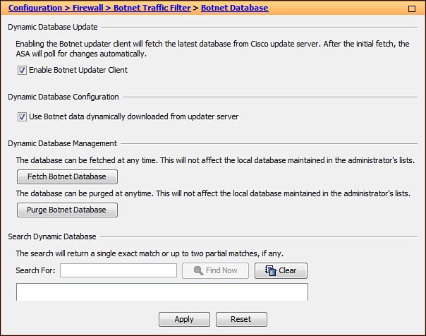
2. Check the Enable Botnet Updater Client check box to enable the Cisco ASA to periodically fetch the latest dynamic BTF database from Cisco.com.
3. Check the Use Botnet Data Dynamically Downloaded from Updater Server check box to allow BTF to use the downloaded database. If you do not check this box, BTF uses only the locally defined blacklist.
4. Click the Fetch Botnet Database button if you want to force the ASA to immediately download the latest dynamic database from Cisco.com.
5. To purge the cached dynamic BTF database, click the Purge Botnet Database button. This does not affect the locally defined blacklist.
6. You can also use the search options in the Search Dynamic Database area to see if the BTF database contains specific hostnames, domain names, or IP addresses. ASA only displays up to two first matches, and you cannot use regex-based patterns when searching.
7. Click Apply.
You can optionally add hostnames, domain names, or IP addresses to the local blacklist or whitelist. The local whitelist overrides entries in the dynamic database. To configure a blacklist or whitelist, complete the following steps:
1. Navigate to Configuration > Firewall > Botnet Traffic Filter > Black and White Lists, as shown in Figure 17-25.

2. Click Add for the White List or Black List.
3. Enter a hostname, a domain name, or an IP address when the dialog box appears. Figure 17-25 shows www.cisco.com in the white list and 192.168.123.100 in the black list. You can enter multiple entries separated by commas, spaces, lines, or semicolons. Each list supports up to 1000 entries.
4. Click Apply.
DNS Snooping
When BTF is enabled, the ASA can compare DNS A and CNAME records against the domain names in the dynamic database and local blacklist. This DNS snooping capability leverages the DNS application inspection engine on the ASA. When DNS snooping is enabled, ASA builds a reverse cache database for all the DNS replies received on interfaces where snooping is enabled. This allows the ASA to identify or block connections to malicious destinations based on IP addresses and domain names alike.
Complete the following steps to enable DNS snooping:
1. Navigate to Configuration > Firewall > Botnet Traffic Filter > DNS Snooping in ASDM, as shown in Figure 17-26.

2. Check the DNS Snooping Enabled check box next to the configured DNS inspection policies to enable snooping using a DNS inspection map. In the example shown in Figure 17-26, DNS snooping uses the default preset_dns_map map under the global policy. Refer to Chapter 13 for a detailed discussion on configuring DNS inspection. You should only enable DNS snooping on interfaces that communicate with external DNS servers. Configure separate inspection policies without DNS snooping for any traffic destined to internal DNS servers.
3. Click Apply.
Traffic Selection
BTF allows you to configure different policies for inspecting or “classifying” transit traffic. Additionally, you can exclude certain interfaces or classes of traffic from BTF inspection. For instance, you could enable traffic classification only on the outside interface because all other interfaces are trusted. When BTF is enabled on a particular interface or for a certain class of traffic, ASA compares the source and destination IP addresses for all associated transit connections against the IP addresses in the dynamic and local blacklists as well as the reverse DNS cache gathered by snooping. If ASA detects a match, it can generate a syslog message or optionally deny the connection.
Complete the following steps and click Apply to enable BTF on ASA interfaces and configure optional actions for blacklisted traffic:
1. Navigate to Configuration > Firewall > Botnet Traffic Filter > Traffic Settings in ASDM, as shown in Figure 17-27.

2. In the Traffic Classification area, check the Traffic Classified box for each interface where you want to apply BTF traffic inspection. BTF inspects all inbound and outbound connections on this interface by default. For each interface, you can also narrow down the inspected traffic with an ACL by selecting an entry in the ACL Used column. For instance, you can create an ACL to only inspect TCP connections on port 80 from a specific network. To add or edit an ACL, click the Manage ACL button to bring up the ACL Manager. You can also apply BTF globally to all interfaces by checking the Traffic Classified box for Global (All Interfaces). In Figure 17-27, BTF inspection applies to all connections through the outside interface.
3. Check the Treat Ambiguous (Greylisted) Traffic as Malicious (Blacklisted) Traffic check box if you want to apply stricter rules to endpoints with uncertain reputation. In this example, BTF treats such hosts as malicious.
4. In the Blacklisted Traffic Actions area, you can create automatic drop rules for malicious traffic. By default, BTF only generates internal statistics and system log messages for blacklisted connections. You can click Add to add a new rule or click Edit to edit an existing one. The dialog box shown in Figure 17-28 opens when you click Add.

This screen has the following options:
![]() Interface: From the drop-down menu, choose one of the BTF-enabled interfaces to apply this rule. In Figure 17-28, the rule applies to outside. The only available action is to Drop a connection.
Interface: From the drop-down menu, choose one of the BTF-enabled interfaces to apply this rule. In Figure 17-28, the rule applies to outside. The only available action is to Drop a connection.
![]() Threat Level: Choose which entries in the dynamic BTF database would fall under the drop rule based on the associated threat level. Click Default to drop connections that involve endpoints with the Moderate and above threat levels. Click Value and choose the lowest threat level to apply the drop rule. You can also click Range and specify a range of threat levels for this purpose. Figure 17-28 blocks connections to and from endpoints with the High and Very High threat levels.
Threat Level: Choose which entries in the dynamic BTF database would fall under the drop rule based on the associated threat level. Click Default to drop connections that involve endpoints with the Moderate and above threat levels. Click Value and choose the lowest threat level to apply the drop rule. You can also click Range and specify a range of threat levels for this purpose. Figure 17-28 blocks connections to and from endpoints with the High and Very High threat levels.
![]() ACL Used: Narrow down which traffic BTF will block by choosing an ACL from the drop-down list. If applicable, this ACL must be a subset of the traffic classification ACL for the given interface. Figure 17-28 uses the default behavior of dropping all matching blacklisted connections.
ACL Used: Narrow down which traffic BTF will block by choosing an ACL from the drop-down list. If applicable, this ACL must be a subset of the traffic classification ACL for the given interface. Figure 17-28 uses the default behavior of dropping all matching blacklisted connections.
5. Click OK and then click Apply.
Refer to Example 17-8 for the complete BTF configuration from the previous steps.
Example 17-8 Sample Complete BTF Configuration
dynamic-filter updater-client enable
dynamic-filter use-database
dynamic-filter enable interface outside
dynamic-filter drop blacklist interface outside threat-level range high very-high
dynamic-filter ambiguous-is-black
dynamic-filter whitelist
name www.cisco.com
dynamic-filter blacklist
address 192.168.123.100 255.255.255.255
!
policy-map global_policy
class inspection_default
inspect dns preset_dns_map dynamic-filter-snoop
Summary
ASA IPS modules seamlessly integrate into the ASA packet processing path and enable multiple levels of protection for transit network traffic. This chapter illustrated how to process different categories of traffic in promiscuous or inline mode on a single ASA IPS module with the help of granular MPF redirection policies. It showed that the CIPS software on ASA IPS comes ready to inspect transit traffic with minimal required configuration. The examples explained how to configure custom signatures, anomaly detection, global correlation, and other advanced features for additional protection. The discussion emphasized that ASA IPS stays up to date by automatically downloading signature and CIPS software packages from Cisco or a designated local server. The chapter also covered the ASA Botnet Traffic Filter feature, which effectively complements ASA IPS policies by identifying and optionally blocking connections to and from known malicious Internet hosts and networks.