Chapter 16. High Availability
This chapter covers the following topics:
Around-the-clock availability is a cornerstone requirement for any modern enterprise network. Any downtime in a critical network infrastructure results in direct monetary damages to the business; some issues make their way into the media and cause significant impact to the brand image. The powerful and flexible high availability capabilities of Cisco ASA ensure that your network is protected from all angles. Even when problems arise, an ASA provides multiple ways of eliminating or minimizing the actual impact to the production applications and users.
The Cisco ASA delivers self-healing capabilities at numerous levels. The simplest forms of highly available configurations involve interface-level redundancy at Layer 2 and static route tracking at Layer 3. More complex designs may utilize failover to deploy fully redundant ASA devices with real-time configuration and stateful session replication. When scalability and availability needs come together, you can leverage clustering to combine up to 16 identical appliances into a single logical firewall system. No matter what combination of the high availability features you enable on the ASA, they operate completely transparently to the protected connections, thus significantly increasing the end-user experience.
Redundant Interfaces
Redundant interfaces represent a basic block of logical abstraction for a pair of physical Ethernet interfaces. When you group two ports into a redundant interface, both physical interfaces share the same configuration and stay operational. However, only one of these ports forwards traffic at any given time; when the currently active interface fails, the other one takes over. You apply the usual interface-level configuration to the corresponding redundant interface instance instead. ASA automatically clears all interface-level configurations under a particular physical port when you assign it to a redundant pair. Individual physical members of a redundant interface only support the following commands for direct configuration:
![]() media-type, speed, and duplex to set the basic physical link characteristics.
media-type, speed, and duplex to set the basic physical link characteristics.
![]() flowcontrol send on to enable generating pause frames toward the adjacent switch when interface oversubscription is detected.
flowcontrol send on to enable generating pause frames toward the adjacent switch when interface oversubscription is detected.
![]() description to add an ASCII comment of up to 200 characters.
description to add an ASCII comment of up to 200 characters.
![]() shutdown to disable and enable the interface. Even though the system enables a redundant interface by default at the time of creation, you have to manually enable the physical member interfaces with the no shutdown command.
shutdown to disable and enable the interface. Even though the system enables a redundant interface by default at the time of creation, you have to manually enable the physical member interfaces with the no shutdown command.
Even though these settings do not have to match between the members of a redundant interface pair, you should ensure compatibility with the directly connected devices, such as switches. After you create a redundant interface, all other ASA configuration will never reference the underlying physical interfaces directly.
Using Redundant Interfaces
You can configure up to eight redundant interfaces in total; each redundant interface can have up to two physical port members. Because a redundant interface represents a link-layer abstraction for the underlying physical links, you have to configure it in the system context when operating in multiple-context mode. Redundant interfaces behave just like any physical Ethernet interfaces; for instance, you would configure subinterfaces and assign them to VLANs directly under the redundant interface instance. Any physical ports can form a redundant interface with the following conditions:
![]() Both interfaces are of the same hardware type: For instance, you cannot group a Gigabit Ethernet interface and a 10-Gigabit Ethernet interface into a redundant pair.
Both interfaces are of the same hardware type: For instance, you cannot group a Gigabit Ethernet interface and a 10-Gigabit Ethernet interface into a redundant pair.
![]() No support for dedicated physical management interfaces: Such interfaces cannot participate in a redundant pair. For example, this includes Management0/0 and Management0/1 interfaces on a Cisco ASA 5585-X appliance. You can use other physical interfaces, such as GigabitEthernet0/0 and GigabitEthernet0/1, to create a dedicated redundant management interface pair.
No support for dedicated physical management interfaces: Such interfaces cannot participate in a redundant pair. For example, this includes Management0/0 and Management0/1 interfaces on a Cisco ASA 5585-X appliance. You can use other physical interfaces, such as GigabitEthernet0/0 and GigabitEthernet0/1, to create a dedicated redundant management interface pair.
![]() No support for Cisco ASA 5505 appliance: It already has a built-in switch that provides interface redundancy at the physical level. Hence, this platform does not support dedicated redundant interfaces.
No support for Cisco ASA 5505 appliance: It already has a built-in switch that provides interface redundancy at the physical level. Hence, this platform does not support dedicated redundant interfaces.
In a redundant interface pair, only one physical port remains active while the other one idles in the standby state. Even though the ASA maintains the link up on both member interfaces, the standby interface discards all incoming frames and never transmits any data. If the link status on the active interface of a redundant pair goes down, the standby interface seamlessly assumes the active role. Because the two member ports never operate in the active state together, the redundant interface instance has a single virtual MAC address to make the switchover completely seamless to the adjacent devices. By default, a redundant interface inherits the MAC address of its first configured member port; if you change the configuration order of the member interfaces after creating a redundant interface instance, the virtual MAC address changes accordingly. To guarantee network stability during interface membership changes, use the mac-address command under the redundant interface instance to manually set a particular virtual MAC address. An active member interface always uses the same virtual MAC address that belongs to the redundant pair.
When the active interface in a redundant pair goes down, the system performs the following steps:
1. If the link state of the standby member interface is up, start the switchover.
2. Clear the virtual MAC address entry from the failed active interface.
3. Move the virtual MAC address to the operational standby interface.
4. Transition the standby interface to the active role, start processing incoming frames, and use that physical port to transmit outgoing traffic for the redundant interface instance.
5. Generate a gratuitous ARP packet on the new active interface to refresh the MAC tables of the adjacent devices.
Keep in mind that the switchover is completely transparent to all transit traffic. Because the ASA configuration and all connection data structures reference the redundant interface pair as a logical block, the physical member failure has no bearing on the overall health of the system. As long as the redundant interface instance remains operational with at least one healthy physical link, Cisco ASA software does not invoke upper-level high availability mechanisms, such as failover or dynamic route reconvergence. Hence, a redundant interface offers nearly instant link switchover, which heavily minimizes or completely eliminates packet drops.
Deployment Scenarios
You can use a redundant interface for any application, but it delivers the most benefit when robust link-level high availability is more important than throughput scalability. Keep in mind that only one member link of a redundant pair stays active at any given time. Although you might prefer to use an EtherChannel for regular data interfaces to take advantage of bandwidth aggregation, a redundant interface comes with much less complexity than Link Aggregation Control Protocol (LACP) and eliminates the need to configure adjacent switches in any particular way. The only basic requirement is for the physical member interfaces to maintain Layer 2 adjacency with the same external endpoints. Other than that, you can connect the underlying ASA ports to independent switches with any degree of geographical separation. This flexibility makes redundant interfaces a good fit for the following types of applications:
![]() Management interfaces: These connections typically do not require much bandwidth, but you want to maintain management access to the ASA at all times.
Management interfaces: These connections typically do not require much bandwidth, but you want to maintain management access to the ASA at all times.
![]() Failover control and stateful links: Because the IP connections on these isolated links establish between the same two devices, EtherChannel does not provide any benefit. However, the health of these control links is extremely important for proper operation of the failover pair.
Failover control and stateful links: Because the IP connections on these isolated links establish between the same two devices, EtherChannel does not provide any benefit. However, the health of these control links is extremely important for proper operation of the failover pair.
Figure 16-1 illustrates a topology where GigabitEthernet0/1 and GigabitEthernet0/2 interfaces of the ASA form a redundant interface. Even though the physical interfaces connect to different switches, the logical redundant instance operates normally as long as both switches maintain Layer 2 connectivity. The corresponding ASA member interfaces typically belong to the same VLAN on both switches, and the inter-switch trunk link extends this VLAN at Layer 2. Because only one physical interface of a redundant pair remains active at any given time, this topology remains loop-free without any Spanning Tree Protocol (STP) involvement.

Configuration and Monitoring
To create a redundant interface, follow these steps:
1. On ASA, identify the physical member interfaces to form a redundant pair and configure them with the appropriate media type, speed, and duplex settings. Be sure to issue the no shutdown command to bring these ports up.
2. On adjacent switches, configure the interfaces that face the redundant member ports of the ASA to provide equivalent Layer 2 connectivity. Remember that the ASA treats both members of a redundant interface pair equally, so the connected switching infrastructure must guarantee connectivity to the same set of endpoints.
3. On ASA, create a redundant interface instance with the interface redundant id command. Pick any numeric interface identifier between 1 and 8.
4. On ASA, assign the physical member ports to the redundant interface instance with the member-interface physical-interface-name command. You can repeat this command up to two times under each redundant interface to link the physical interface pair.
5. Continue configuring the redundant interface as you would set up any regular physical interface on the ASA. For instance, configure it with the nameif command under an application context or assign with the allocate-interface command in the system context when using multiple-context mode.
Example 16-1 shows a complete interface configuration where the inside ASA interface relies on physical ports GigabitEthernet0/6 and 0/7 for link-layer redundancy. Notice that, for illustrative purposes, the link duplex setting on GigabitEthernet0/6 does not match that of GigabitEthernet0/7; you would typically configure both physical interfaces to have a matching configuration.
Example 16-1 Redundant Interface Configuration
interface GigabitEthernet0/6
duplex full
no nameif
no security-level
no ip address
!
interface GigabitEthernet0/7
no nameif
no security-level
no ip address
!
interface Redundant1
member-interface GigabitEthernet0/6
member-interface GigabitEthernet0/7
nameif inside
security-level 100
ip address 192.168.1.1 255.255.255.0
Use the show interface command to monitor the status of a redundant interface instance. Because only one member link stays active at any given time, the traffic statistics of the corresponding redundant interface aggregate the physical port information over time. As Example 16-2 shows, the command also reports the currently active member and the time and date of the last switchover event.
Example 16-2 Monitoring Redundant Interface Statistics
asa# show interface Redundant 1
Interface Redundant1 "inside", is up, line protocol is up
Hardware is bcm56801 rev 01, BW 1000 Mbps, DLY 10 usec
Full-Duplex(Full-duplex), Auto-Speed(1000 Mbps)
Input flow control is unsupported, output flow control is off
MAC address 5475.d029.885c, MTU 1500
IP address unassigned
805 packets input, 62185 bytes, 0 no buffer
Received 1 broadcasts, 0 runts, 0 giants
[...]
Traffic Statistics for "inside":
1 packets input, 46 bytes
0 packets output, 0 bytes
0 packets dropped
1 minute input rate 0 pkts/sec, 0 bytes/sec
1 minute output rate 0 pkts/sec, 0 bytes/sec
1 minute drop rate, 0 pkts/sec
5 minute input rate 0 pkts/sec, 0 bytes/sec
5 minute output rate 0 pkts/sec, 0 bytes/sec
5 minute drop rate, 0 pkts/sec
Redundancy Information:
Member GigabitEthernet0/6(Active), GigabitEthernet0/7
Last switchover at 15:37:10 UTC Jun 11 2013
Static Route Tracking
At this time, Cisco ASA software does not support load balancing between multiple egress interfaces for the same destination network. The system supports up to three overlapping static routes with all of the next-hop routers residing behind the same logical interface; dynamic routing protocols have the same limitation. This limitation stems from the need to maintain flow symmetry in the stateful connection table.
When using an ASA as the edge firewall, you can have only one active connection to the upstream Internet service provider (ISP). However, your network design may call for a backup interface toward another ISP to satisfy the high availability requirements. One option is to deploy an upstream router to perform egress load balancing with uplink redundancy; this design eliminates the benefits of the high-speed ASA Network Address Translation (NAT) subsystem. A better approach is to create a backup Internet interface on the ASA itself. The firewall does not use that interface to forward egress traffic under normal circumstances, but if the primary ISP link fails, the connection becomes active. The interface switchover occurs by automatically changing the default route when an ASA detects a certain failure condition along the primary egress path. The following elements enable this route tracking capability:
![]() Service Level Agreement (SLA) monitor: This module checks external network reachability status across the primary ISP path and feeds this reachability data into the routing subsystem.
Service Level Agreement (SLA) monitor: This module checks external network reachability status across the primary ISP path and feeds this reachability data into the routing subsystem.
![]() Primary floating static or DHCP/PPPoE default route: The primary default route remains active as long as the SLA monitor confirms path reachability. ASA removes this route from the routing table if the primary ISP link loses external connectivity.
Primary floating static or DHCP/PPPoE default route: The primary default route remains active as long as the SLA monitor confirms path reachability. ASA removes this route from the routing table if the primary ISP link loses external connectivity.
![]() Secondary default route: This route has a higher administrative distance, so it becomes active only when the primary default route disappears from the routing table based on the SLA monitor action.
Secondary default route: This route has a higher administrative distance, so it becomes active only when the primary default route disappears from the routing table based on the SLA monitor action.
Configuring Static Routes with an SLA Monitor
An SLA monitor sends a period network reachability probe to a certain destination. As long as the destination is reachable, the monitor instance reports a successful status to the routing subsystem. If the SLA test fails, the ASA removes any associated routes from the routing table. Keep in mind that the SLA monitor instance continues to run, so the associated floating routes can return to the system when network connectivity to the monitored destination comes back up.
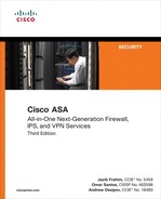
Add a new static route in ASDM by navigating to Configuration > Device Setup > Routing > Static Routes and clicking Add, or change an existing route by selecting it on the same screen and clicking Edit. Figure 16-2 illustrates the configuration dialog box that opens.
You can follow these steps to configure a static route with tracking:
1. At the top of the dialog box, specify the IP address type, egress interface, destination network prefix, and gateway IP address as you would with any regular static route. The example shown in Figure 16-2 installs a default route on the outside interface through 172.16.164.97 as the gateway.
2. If desired, configure a specific value in the Metric field. Keep in mind that the primary route should always have a lower metric value than the floating backup route. The default value is 1.
3. Click Tracked from the list of options.
4. Specify numerical values for the Track ID and SLA ID fields. Track ID refers to the route tracking group, and SLA ID specifies an associated SLA monitor instance. These values do not have to be the same. This example uses 1 for both identifiers.
5. Set the Track IP Address field to an address of a host that the system should probe when checking path reachability through this route. You should ideally use some endpoint on the Internet rather than the IP address of the default gateway itself; the idea is to monitor external connectivity through this particular ISP. The only supported method of verifying reachability is ICMP Echo Request, so the destination must reply to these packets. Use the ping command from the ASA to verify reachability to this destination first. This example uses 72.163.47.11, which is Cisco.com.
6. From the Target Interface drop-down menu, choose which interface generates the reachability probes. Keep in mind that the system always sources the probes from this interface; this allows ASA to restore the primary route if the tracked destination becomes reachable again. It is typically the same as the next-hop interface for this route, so this example uses the outside interface.
7. Optionally, you can click Monitoring Options to modify the default probe parameters. You can choose how often the reachability tests occurs, how many ICMP Echo Requests the system generates with every test and how large they are, set specific ToS values for these packets, and tune the response timeouts. Keep in mind that a single ICMP Echo Reply received within a configured time window is sufficient to declare the route healthy.
Follow Steps 1 and 2 to configure the backup route as well. Note that, for the floating concept to work, the Metric value for such a route must be numerically higher than what you configured for the primary route. The route with a numerically lower metric always gets precedence in the ASA routing table, unless the associated SLA monitor instance indicates a path failure. Do not configure route tracking for the backup route, unless you intend to provision multiple secondary paths out of the network.
Floating Connection Timeout
Once established, stateful connection entries in the ASA continue to use the original egress interface as long as it remains up. In order for these flows to be rebuilt with a new egress interface, the original egress interface must undergo a complete link failure. Even if the primary route changes to the backup route after route tracking detects an upstream failure, such preexisting connections will not recover gracefully until they are torn down after the idle timeout. A similar problem occurs when the primary path becomes healthy again and the associated default route takes precedence in the routing table over the floating backup route. Whereas TCP-based applications may recover from the route switchover relatively quickly, other connections may suffer from a prolonged downtime. Furthermore, the stateful connection table on the ASA wastes valuable resources by storing the stale entries.
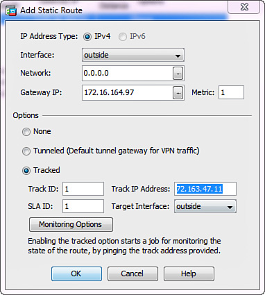
To get around this problem, configure existing connections to automatically time out if the best routes to the source or destination IP address change. This floating connection timeout is disabled by default, but you can configure it in ASDM by navigating to Configuration > Firewall > Advanced > Global Timeouts. Figure 16-3 shows a configuration where all matching connections time out in 1 minute if any associated routes change.
Sample Backup ISP Deployment
Figure 16-4 depicts a basic network topology that involves an ASA with two Internet-facing interfaces, named outside1 and outside2.

Assuming that the interface and security policy configuration is complete, you need to configure primary and backup floating default routes with route tracking. The reachability probe of the primary path has the following requirements:
![]() Monitor www.cisco.com at 72.163.47.11 from the ASA interface that faces the primary ISP.
Monitor www.cisco.com at 72.163.47.11 from the ASA interface that faces the primary ISP.
![]() Probe with three ICMP Echo Request packets every 2 minutes.
Probe with three ICMP Echo Request packets every 2 minutes.
![]() Declare the primary path as failed and remove the associated default route if no response arrives from the monitored destination within 4 seconds.
Declare the primary path as failed and remove the associated default route if no response arrives from the monitored destination within 4 seconds.
The following steps define and initiate the SLA monitor and tracking instances, associate them with the primary default route, and create a floating backup route:
1. Configure an SLA monitor instance to conform to the preceding requirements:
asa(config)# sla monitor 1
asa(config-sla-monitor)# type echo protocol ipIcmpEcho 72.163.47.11 interface
outside1
asa(config-sla-monitor-echo)# frequency 120
asa(config-sla-monitor-echo)# num-packets 3
asa(config-sla-monitor-echo)# timeout 4000
asa(config-sla-monitor-echo)# exit
Make sure to specify the probe frequency in seconds and the timeout in milliseconds.
2. Start the monitoring process for the configured SLA instance. You can trigger it at a certain time of day and terminate after a predefined duration in a recurring fashion. In a typical configuration, you start the probe right away and make it run continuously:
asa(config)# sla monitor schedule 1 life forever start-time now
3. Verify that the monitored path is healthy with the show sla monitor operational-state command. This avoids unexpected primary path switchovers when the primary static default route attaches to the tracking instance. The output displays additional useful data, including the number of attempted operations and round-trip time statistics.
asa# show sla monitor operational-state
Entry number: 1
Modification time: 15:19:46.740 PDT Fri Aug 30 2013
Number of Octets Used by this Entry: 1660
Number of operations attempted: 18
Number of operations skipped: 0
Current seconds left in Life: Forever
Operational state of entry: Active
Last time this entry was reset: Never
Connection loss occurred: FALSE
Timeout occurred: FALSE
Over thresholds occurred: FALSE
Latest RTT (milliseconds): 1
Latest operation start time: 15:53:46.741 PDT Fri Aug 30 2013
Latest operation return code: OK
RTT Values:
RTTAvg: 1 RTTMin: 1 RTTMax: 1
NumOfRTT: 3 RTTSum: 3 RTTSum2: 3
4. Create a static route tracking instance and associate it with the SLA monitor instance; use the same ID values for simplicity:
asa(config)# track 1 rtr 1 reachability
5. Configure the primary default route and tie it to the route tracking instance. As long as the associated SLA monitor process indicated that the link is healthy, the route remains in the routing table.
asa(config)# route outside1 0.0.0.0 0.0.0.0 198.51.100.1 track 1
6. Configure the backup default route with a numerically higher metric, which gives it a lower priority as compared to the primary route. The default metric for static routes is 1, so set it to any higher value.
asa(config)# route outside2 0.0.0.0 0.0.0.0 203.0.113.1 100
7. Configure the existing connections to time out 30 seconds after any of the related routes switch over to a different interface:
asa(config)# timeout floating-conn 0:0:30
Refer to Example 16-3 for the complete SLA monitor, static route, and floating connection timeout configuration on the ASA.
Example 16-3 Complete Floating Static Route Configuration with Tracking
route outside 0.0.0.0 0.0.0.0 198.51.100.1 track 1
route outside 0.0.0.0 0.0.0.0 203.0.113.1 100
!
timeout floating-conn 0:00:30
!
sla monitor 1
type echo protocol ipIcmpEcho 72.163.47.11 interface outside1
num-packets 3
timeout 4000
frequency 120
!
sla monitor schedule 1 life forever start-time now
!
track 1 rtr 1 reachability
Failover
Cisco ASA failover is the legacy high availability mechanism that primarily provides redundancy rather than capacity scaling. While Active/Active failover can help with distributing traffic load across a failover pair or devices, there are significant practical implications in its scalability, as discussed in the “Active/Standby and Active/Active Failover” section. Leverage failover to group a pair of identical ASA appliances or modules into a fully redundant firewall entity with centralized configuration management and optional stateful session replication. When one unit in the failover pair is no longer able to pass transit traffic, its identical peer seamlessly takes over with minimal or no impact on your secure network.
Unit Roles and Functions in Failover
When configuring the failover pair, designate one unit as primary and the other one as secondary. These are statically configured roles that never change during failover operation. While the failover subsystem could use these designations to resolve certain operational conflicts, either the primary or the secondary unit may pass transit traffic while operating in an active role while its peer remains in a standby state. Thus, dynamic active and standby roles pass between the statically defined primary and secondary units depending on the operational state of the failover pair.
The responsibilities of the active unit include the following items:
![]() Accept configuration commands from the user and replicate them to the standby peer. All management and monitoring of a failover pair should happen on the active unit, because configuration replication is not a two-way process. If you make any changes on the standby ASA, it causes a configuration inconsistency that may prevent subsequent command synchronization and create issues after a switchover event. If you inadvertently made a change on the standby device, exit the configuration mode and issue the write standby command on the active unit to restore proper state. This command completely overwrites the existing running configuration of the standby unit with the running configuration of the active ASA.
Accept configuration commands from the user and replicate them to the standby peer. All management and monitoring of a failover pair should happen on the active unit, because configuration replication is not a two-way process. If you make any changes on the standby ASA, it causes a configuration inconsistency that may prevent subsequent command synchronization and create issues after a switchover event. If you inadvertently made a change on the standby device, exit the configuration mode and issue the write standby command on the active unit to restore proper state. This command completely overwrites the existing running configuration of the standby unit with the running configuration of the active ASA.
![]() Process all transit traffic, apply configured security policies, build and tear down connections, and synchronize the connection information to the standby unit if configured for stateful failover.
Process all transit traffic, apply configured security policies, build and tear down connections, and synchronize the connection information to the standby unit if configured for stateful failover.
![]() Send NetFlow Secure Event Logging (NSEL) and syslog messages to the configured event collectors. When necessary, you may configure the standby unit to transmit syslog messages with the logging standby command. Keep in mind that this command doubles the connection-related syslog traffic from the failover pair.
Send NetFlow Secure Event Logging (NSEL) and syslog messages to the configured event collectors. When necessary, you may configure the standby unit to transmit syslog messages with the logging standby command. Keep in mind that this command doubles the connection-related syslog traffic from the failover pair.
![]() Build and maintain dynamic routing adjacencies. The standby unit never participates in dynamic routing.
Build and maintain dynamic routing adjacencies. The standby unit never participates in dynamic routing.
Stateful Failover
By default, failover operates in a stateless manner. In this configuration, the active unit only synchronizes its configuration to the standby device. All of the stateful flow information remains local to the active ASA, so all connections must re-establish upon a failover event. While this configuration preserves ASA processing resources, most high availability configurations require stateful failover. To pass state information to the standby ASA, you must configure a stateful failover link, as discussed in the “Stateful Link” section. Stateful failover is not available on the Cisco ASA 5505 platform. When stateful replication is enabled, an active ASA synchronizes the following additional information to the standby peer:
![]() Stateful table for TCP and UDP connections. To preserve processing resources, ASA does not synchronize certain short-lived connections by default. For example, HTTP connections over TCP port 80 remain stateless unless you configure the failover replication http command. Similarly, ICMP connections only synchronize in Active/Active failover with Asymmetric Routing (ASR) groups configured. Note that enabling stateful replication for all connections may cause up to a 30 percent reduction in the maximum connection setup rate supported by the particular ASA platform.
Stateful table for TCP and UDP connections. To preserve processing resources, ASA does not synchronize certain short-lived connections by default. For example, HTTP connections over TCP port 80 remain stateless unless you configure the failover replication http command. Similarly, ICMP connections only synchronize in Active/Active failover with Asymmetric Routing (ASR) groups configured. Note that enabling stateful replication for all connections may cause up to a 30 percent reduction in the maximum connection setup rate supported by the particular ASA platform.
![]() ARP table and bridge-group MAC mapping table when running in transparent mode.
ARP table and bridge-group MAC mapping table when running in transparent mode.
![]() Routing table, including any dynamically learned routes. All dynamic routing adjacencies must re-establish after a failover event, but the new active unit continues to forward traffic based on the previous routing table state until full reconvergence.
Routing table, including any dynamically learned routes. All dynamic routing adjacencies must re-establish after a failover event, but the new active unit continues to forward traffic based on the previous routing table state until full reconvergence.
![]() Certain application inspection data, such as General Packet Radio Service (GPRS), Tunneling Protocol (GTP), Packet Data Protocol (PDP), and Session Initiation Protocol (SIP) signaling tables. Keep in mind that most application inspection engines do not synchronize their databases because of resource constraints and complexity, so such connections switch over at the Layer 4 level only. As the result, some of these connections may have to reestablish after a failover event.
Certain application inspection data, such as General Packet Radio Service (GPRS), Tunneling Protocol (GTP), Packet Data Protocol (PDP), and Session Initiation Protocol (SIP) signaling tables. Keep in mind that most application inspection engines do not synchronize their databases because of resource constraints and complexity, so such connections switch over at the Layer 4 level only. As the result, some of these connections may have to reestablish after a failover event.
![]() Most VPN data structures, including security associations (SA) for site-to-site tunnels and remote-access users. Only some clientless SSL VPN information remains stateless.
Most VPN data structures, including security associations (SA) for site-to-site tunnels and remote-access users. Only some clientless SSL VPN information remains stateless.
Keep in mind that stateful failover covers only Cisco ASA software features. IPS, Content Security and Control (CSC), and CX application modules track connection state independently and do not synchronize their configurations or any other stateful data in failover. When an ASA switchover occurs, these modules typically recover existing connections transparently to the user, but some advanced security checks may apply only to new flows that are established through the newly active ASA and its local application module.
Active/Standby and Active/Active Failover
Active/Standby failover delivers device-level redundancy where one unit in a failover pair is always active and the other one is standby. The standby device drops all transit traffic that it may receive and only accepts management connections. For a switchover to occur automatically, the active unit must become less operationally healthy than the standby. The failover event moves all transit traffic to the peer device even if the actual impact on the previously active unit is localized. When running in multiple-context mode, all contexts switch over at the same time. Active/Standby failover is the only option when running in single-context mode.
All ASA models except the Cisco ASA 5505 also support Active/Active failover when operating in multiple-context mode. In this configuration, split the traffic load between members of the failover pair so that each unit is active for some set of security contexts. This way, both failover peers are passing traffic concurrently and fully utilizing their respective hardware resources. This separation is achieved by assigning specific application contexts to one of the two failover groups. Then make each of the failover peers own one of these groups. As opposed to Active/Standby failover, where all contexts switch over to the peer on active unit failure, this model localizes the impact to the contexts in a particular failover group. In total, an ASA supports three failover groups when configured for Active/Active failover:
![]() Group 0: This is a hidden, nonconfigurable group that covers only the system context. It is always active on the same unit that is active for group 1.
Group 0: This is a hidden, nonconfigurable group that covers only the system context. It is always active on the same unit that is active for group 1.
![]() Group 1: All newly created contexts belong to this group by default. The admin context must always be a member of this group. By default, the primary unit owns this group, and you would typically keep it this way.
Group 1: All newly created contexts belong to this group by default. The admin context must always be a member of this group. By default, the primary unit owns this group, and you would typically keep it this way.
![]() Group 2: Use this group to assign some contexts to be active on the secondary unit. The primary unit also owns this group by default, so you have to change its ownership to the secondary ASA after assigning all of the desired contexts. Keep in mind that both groups have to be active on the same unit in order to move contexts between groups 1 and 2.
Group 2: Use this group to assign some contexts to be active on the secondary unit. The primary unit also owns this group by default, so you have to change its ownership to the secondary ASA after assigning all of the desired contexts. Keep in mind that both groups have to be active on the same unit in order to move contexts between groups 1 and 2.
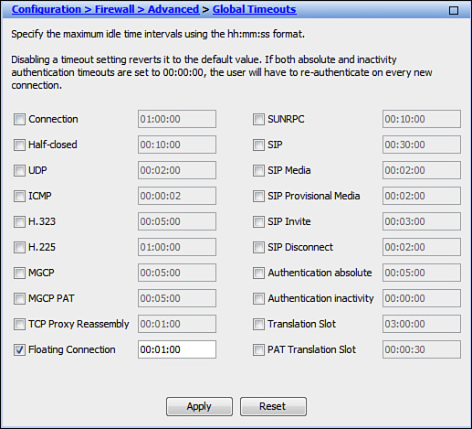
You should deploy Active/Active failover only when you can effectively separate the network traffic flows into these two independent groups. Keep in mind that interface sharing is not supported between contexts that belong to different failover groups. Figure 16-5 shows a typical network design where Active/Active failover is appropriate.
In this instance, a service provider supports security services for two customers, Alpha and Bravo. Each customer has its own inside and outside interfaces, so they are assigned to contexts A and B respectively. Context A is a member of failover group 1, which is active on the primary ASA, and Context B is a member of failover group 2, which is active on the secondary ASA. Because traffic flows for the two customers are completely independent, Active/Active failover effectively splits this load between two hardware appliances.
Although Active/Active failover offers some benefits of load sharing, consider the following implications of this model:
![]() You must be able to separate the traffic flows into multiple contexts, such that no interfaces are shared between contexts in different failover groups. Keep in mind that not all features are supported in multiple-context mode.
You must be able to separate the traffic flows into multiple contexts, such that no interfaces are shared between contexts in different failover groups. Keep in mind that not all features are supported in multiple-context mode.
![]() If a switchover occurs, a single physical device must carry the full traffic load that was originally intended for two ASA units. This effectively reduces the benefits of load balancing, because you should only plan the overall load on the failover pair for this worst-case scenario with a single remaining unit.
If a switchover occurs, a single physical device must carry the full traffic load that was originally intended for two ASA units. This effectively reduces the benefits of load balancing, because you should only plan the overall load on the failover pair for this worst-case scenario with a single remaining unit.
![]() When using stateful failover, the standby device requires as much processing power as the active one to create new connections; the only difference is that the standby unit does not have to accept transit traffic from the network. When you enable stateful replication with Active/Active failover, you significantly reduce the available processing capacity of each failover pair member.
When using stateful failover, the standby device requires as much processing power as the active one to create new connections; the only difference is that the standby unit does not have to accept transit traffic from the network. When you enable stateful replication with Active/Active failover, you significantly reduce the available processing capacity of each failover pair member.
Generally speaking, Active/Standby is the preferred deployment model for failover. Consider clustering instead of Active/Active failover when your ASA deployment scenario requires load sharing.
Failover Hardware and Software Requirements
When grouping two devices in failover, the following hardware parameters must be identical:
![]() Exact model number: For instance, you cannot configure failover between an ASA 5585-X with an SSP-60 and another ASA 5585-X with an SSP-40. You can only pair up an SSP-60 with another SSP-60.
Exact model number: For instance, you cannot configure failover between an ASA 5585-X with an SSP-60 and another ASA 5585-X with an SSP-40. You can only pair up an SSP-60 with another SSP-60.
![]() Physical interfaces and network connections: Both units must have the same number, type, and order of physical interfaces. When using interface expansion cards, you cannot use copper-based interfaces on one appliance and fiber-based interfaces on the other one. When installing interface cards into an ASA 5580, make sure that you populate matching slots with the same cards between the two chassis. Network connections for all active data interfaces must be mirrored exactly as well. For instance, if you intend to configure and use GigabitEthernet0/0 interfaces in your failover installation, you must connect this interface of each unit in the failover pair to the same network segment with full Layer 2 adjacency.
Physical interfaces and network connections: Both units must have the same number, type, and order of physical interfaces. When using interface expansion cards, you cannot use copper-based interfaces on one appliance and fiber-based interfaces on the other one. When installing interface cards into an ASA 5580, make sure that you populate matching slots with the same cards between the two chassis. Network connections for all active data interfaces must be mirrored exactly as well. For instance, if you intend to configure and use GigabitEthernet0/0 interfaces in your failover installation, you must connect this interface of each unit in the failover pair to the same network segment with full Layer 2 adjacency.
![]() Feature modules: If one unit has a hardware or software security module installed, its failover peer must have the exact same module as well. You cannot group one unit with an IPS SSP and another one with a CX SSP.
Feature modules: If one unit has a hardware or software security module installed, its failover peer must have the exact same module as well. You cannot group one unit with an IPS SSP and another one with a CX SSP.
![]() Amount of RAM and system flash: Although these parameters are not strictly enforced in Cisco ASA software, you should make sure that they match between a failover pair. Otherwise, you may end up in a situation where one unit is unable to carry the same traffic load as its peer after a switchover.
Amount of RAM and system flash: Although these parameters are not strictly enforced in Cisco ASA software, you should make sure that they match between a failover pair. Otherwise, you may end up in a situation where one unit is unable to carry the same traffic load as its peer after a switchover.
When using ASA Services Modules, the host chassis configurations do not have to match. Cisco ASA software has no visibility into the host chassis information.
Zero Downtime Upgrade in Failover
Both failover peers should run the same software image during normal operation, but running different software versions during an upgrade is allowed. Zero Downtime upgrade capability allows full stateful failover synchronization from an active ASA running older code to the standby unit on newer software. A typical recommendation is to upgrade from the last maintenance image in the current train to the latest maintenance image of the desired later train. For instance, you should upgrade to version 8.2(5) first if you want to move from 8.2(3) to 8.4(7). Even though 8.2 and 8.4 trains use a different configuration format for many commands, Zero Downtime upgrade capability is still supported. Follow these steps in the system context of the ASA failover pair to perform such an upgrade:
1. Load the desired images into the flash file system of both primary and secondary units separately. Keep in mind that the system and ASDM images do not automatically synchronize in failover.
2. On the active unit, change the boot system command to point to the new image. Keep in mind that you may have to use the clear configure boot system command to remove the previous ASA boot settings. This change is automatically synchronized to the standby firewall.
3. On the active unit, issue the write memory command to save the running configuration and update the boot variable. This command also automatically saves the configuration on the standby ASA.
4. On the standby unit, use the reload command to boot the new image. At this time, the active unit continues to forward transit traffic with no disruption to the network.
5. Wait for the standby unit to boot and synchronize the configuration and stateful connection table from the active ASA. The new software automatically converts the configuration to the new format, if necessary. Use the show failover command to confirm that the upgraded unit is in the Standby Ready state.
6. Use the failover active command on the standby unit to transition it to the active state. Transit network connectivity should remain uninterrupted. If you are managing your ASA remotely through Telnet, SSH, or ASDM, you need to reconnect to the active device upon the switchover.
7. Connect to the new standby (formerly active) ASA and verify that it is running the old software image with the show version command. Use the reload command on this unit to boot the new image.
8. Wait for the new standby ASA to boot and synchronize the configuration and stateful connection table from the active unit. If desired, you can transition it back to the active state by issuing the no failover active command on the currently active unit. This step returns your failover pair to the initial operational state.
Failover Licensing
Prior to Cisco ASA Software version 8.3(1), both units in a failover pair must also have exact same feature licenses. This leads to inefficient usage of feature licenses, especially when only one unit in the pair is actively passing traffic at any given time. In later software versions, only the following licensing constraints remain between the failover peers:
![]() Cisco ASA 5505, ASA 5510, and ASA 5512-X appliances must have the Security Plus license installed.
Cisco ASA 5505, ASA 5510, and ASA 5512-X appliances must have the Security Plus license installed.
![]() The state of the Encryption-3DES-AES license must match between the units. In other words, it must be either disabled or enabled on both failover peers.
The state of the Encryption-3DES-AES license must match between the units. In other words, it must be either disabled or enabled on both failover peers.
All other licensed features and capacities combine to form a single licensed feature set for the failover pair. Refer to the “Combined Licenses in Failover and Clustering” section in Chapter 3, “Licensing,” for a detailed description of the license aggregation rules in failover.
Failover Interfaces
When configuring an ASA failover pair, dedicate one physical interface of each appliance or one VLAN on each ASA Services Module to the failover control link. You can use a VLAN subinterface on an ASA for this purpose, but you cannot configure any other subinterfaces on the same physical interface to pass regular traffic. The physical interface or subinterface name must match between the failover peers. For instance, you cannot configure GigabitEthernet0/3.100 as the failover control interface on the primary and GigabitEthernet0/2 on the secondary unit. Both peers can use the GigabitEthernet0/3.100 subinterface as the failover control link as long as there are no other named subinterfaces under GigabitEthernet0/3. ASA units in a failover pair use this control link for the following purposes:
![]() Initial failover peer discovery and negotiation
Initial failover peer discovery and negotiation
![]() Configuration replication from the active unit to its standby peer
Configuration replication from the active unit to its standby peer
![]() Device-level health monitoring
Device-level health monitoring
The failover control link requires a dedicated subnet with direct, unimpeded Layer 2 connectivity between the failover peers. Assign IP addresses to the primary and secondary units on this failover control subnet; this segment cannot overlap with any data interfaces. Unlike data interface address assignments, discussed shortly, IP address assignments on the failover control link never change between the failover peers during operation. Because the failover control link is absolutely critical for proper operation of the failover pair, consider the following guidelines for protecting it:
![]() Use a redundant interface pair on appliances and an EtherChannel between switch chassis: Because all communication on the failover control link happens between only two IP addresses, there is no benefit from using an EtherChannel for bandwidth aggregation, with the associated overhead and complexity. The volume of control traffic on this interface is quite low, so a redundant pair of Gigabit Ethernet interfaces is sufficient on ASA appliances. When configuring ASA Services Modules in different chassis, use a dedicated EtherChannel to carry the failover control VLAN between the host switches.
Use a redundant interface pair on appliances and an EtherChannel between switch chassis: Because all communication on the failover control link happens between only two IP addresses, there is no benefit from using an EtherChannel for bandwidth aggregation, with the associated overhead and complexity. The volume of control traffic on this interface is quite low, so a redundant pair of Gigabit Ethernet interfaces is sufficient on ASA appliances. When configuring ASA Services Modules in different chassis, use a dedicated EtherChannel to carry the failover control VLAN between the host switches.
![]() Connect the failover peers back-to-back without an intermediate switch: The direct connection reduces complexity and eliminates the possibility of an indirect link failure. The only downside of this approach is the uncertainty in troubleshooting physical interface problems; if the link on one of the physical interface members goes down, you cannot easily tell which of the two ASA units has a failed interface without additional testing.
Connect the failover peers back-to-back without an intermediate switch: The direct connection reduces complexity and eliminates the possibility of an indirect link failure. The only downside of this approach is the uncertainty in troubleshooting physical interface problems; if the link on one of the physical interface members goes down, you cannot easily tell which of the two ASA units has a failed interface without additional testing.
![]() Isolate failover control VLAN: When using intermediate switches or pairing up ASA Services Modules, ensure that the failover control VLAN is fully isolated. Disable STP on this VLAN or enable the STP PortFast feature on the switch ports that face the appliances.
Isolate failover control VLAN: When using intermediate switches or pairing up ASA Services Modules, ensure that the failover control VLAN is fully isolated. Disable STP on this VLAN or enable the STP PortFast feature on the switch ports that face the appliances.
Stateful Link
Stateful failover requires you to configure a separate link for passing the additional information from the active unit to its standby peer. Refer to the “Stateful Failover” section earlier in this chapter for some examples of this optionally synchronized data. The requirements are similar to the failover control link, but with some notable differences:
![]() Failover stateful and control links can share a physical interface: You can even configure the existing failover control interface to double as the stateful link, but this is not a recommended approach because of the high potential volume of stateful updates. If you want to minimize the risk of overloading the failover control link and causing a disruption in failover operation, the stateful link should use a separate physical interface whenever possible.
Failover stateful and control links can share a physical interface: You can even configure the existing failover control interface to double as the stateful link, but this is not a recommended approach because of the high potential volume of stateful updates. If you want to minimize the risk of overloading the failover control link and causing a disruption in failover operation, the stateful link should use a separate physical interface whenever possible.
![]() A single Gigabit Ethernet interface is sufficient: You may still use a redundant interface pair for the stateful failover link when spare interfaces are available, but its health is not as critical to the failover pair operation. Because the bulk of the failover stateful link load comes from connection build and teardown notifications, its peak traffic rates should not exceed 1 Gbps on all platforms, including those with 10-Gigabit Ethernet interfaces.
A single Gigabit Ethernet interface is sufficient: You may still use a redundant interface pair for the stateful failover link when spare interfaces are available, but its health is not as critical to the failover pair operation. Because the bulk of the failover stateful link load comes from connection build and teardown notifications, its peak traffic rates should not exceed 1 Gbps on all platforms, including those with 10-Gigabit Ethernet interfaces.
![]() Low latency is very important: To avoid unnecessary message retransmissions and the associated reduction in ASA performance, one-way latency on the stateful link should not exceed 10 ms. The maximum acceptable latency on this link is 250 ms.
Low latency is very important: To avoid unnecessary message retransmissions and the associated reduction in ASA performance, one-way latency on the stateful link should not exceed 10 ms. The maximum acceptable latency on this link is 250 ms.
Failover Link Security
By default, ASA failover peers exchange all information about the failover control and stateful links in clear text. If you terminate VPN tunnels on the ASA, this includes configured usernames, passwords, and preshared keys. Although this may be acceptable for a direct back-to-back connection between the appliances, you should protect failover communication with one of the following methods when connecting the failover links through intermediate devices:
![]() Shared encryption key: This key provides a simple form of MD5 authentication and encryption for all failover control and stateful link messages. The failover key command enables this method of failover encryption. Use either a string of letters, numbers, and punctuation with 1 to 63 characters or a hexadecimal value of up to 32 digits. Only use this option when running Cisco ASA Software versions earlier than 9.1(2) or deploying stateless failover.
Shared encryption key: This key provides a simple form of MD5 authentication and encryption for all failover control and stateful link messages. The failover key command enables this method of failover encryption. Use either a string of letters, numbers, and punctuation with 1 to 63 characters or a hexadecimal value of up to 32 digits. Only use this option when running Cisco ASA Software versions earlier than 9.1(2) or deploying stateless failover.
![]() IPsec site-to-site tunnel: This is the more secure approach to failover link protection, so always use it in Cisco ASA Software version 9.1(2) and later. The failover ipsec pre-shared-key command enables this method of failover encryption. The only parameter that you need to specify is the preshared key, which can be up to 128 characters in length. Other tunnel parameters establish automatically between the failover peers, and this special IPsec connection does not count against the licensed platform capacity for site-to-site tunnels. This method takes precedence over the shared encryption key when you configure both on the same failover pair. You must deploy stateful failover to use this feature.
IPsec site-to-site tunnel: This is the more secure approach to failover link protection, so always use it in Cisco ASA Software version 9.1(2) and later. The failover ipsec pre-shared-key command enables this method of failover encryption. The only parameter that you need to specify is the preshared key, which can be up to 128 characters in length. Other tunnel parameters establish automatically between the failover peers, and this special IPsec connection does not count against the licensed platform capacity for site-to-site tunnels. This method takes precedence over the shared encryption key when you configure both on the same failover pair. You must deploy stateful failover to use this feature.
You can use the global Master Passphrase feature to encrypt both the failover shared encryption and preshared IPsec keys in the ASA configuration.
Data Interface Addressing
Failover provides very effective first-hop redundancy capabilities by allowing the MAC and IP address pair on each data interface to move between the failover peers based on which unit is active at any given time. Because all physical interface connections and their configurations are identical between the members of a failover pair, active ASA unit switchovers are completely transparent to the adjacent network devices and endpoints. When you enable failover, the IP address configured on each data interface becomes the active one. When the active unit fails, the standby peer automatically assumes ownership of these addresses upon taking over the active role and seamlessly picks up transit traffic processing.
To support additional failover health monitoring capabilities and allow management connectivity to the standby interfaces, always configure each data interface with an optional standby IP address. The standby IP address must reside on the same IP subnet as the active address. When a failover event occurs, the peers exchange the ownership of active and standby addresses.
By default, the burned-in MAC address of the ASA designated as primary in the failover pair corresponds to the active IP address of the given data interface, and the burned-in MAC address of the secondary unit corresponds to the standby address of the same interface. To maintain seamless switchovers in the event of a failover, the units swap both the active MAC and IP addresses for each data interface; if you do not configure a standby IP address, no standby MAC address is maintained either. Because active MAC address changes may cause network connectivity disruptions on adjacent devices, consider the following:
![]() The secondary active unit continues to use the primary unit’s MAC addresses as active even when the primary is removed from the failover pair to avoid disruption. If you replace the primary with a different physical unit, the active MAC addresses change immediately after the new primary device rejoins the failover pair. This happens even if the secondary ASA retains the active role.
The secondary active unit continues to use the primary unit’s MAC addresses as active even when the primary is removed from the failover pair to avoid disruption. If you replace the primary with a different physical unit, the active MAC addresses change immediately after the new primary device rejoins the failover pair. This happens even if the secondary ASA retains the active role.
![]() If the primary unit is not present when the secondary ASA boots up, the secondary peer starts using its own burned-in MAC addresses as active on all data interfaces. When the primary unit rejoins the failover pair, the active MAC addresses change immediately.
If the primary unit is not present when the secondary ASA boots up, the secondary peer starts using its own burned-in MAC addresses as active on all data interfaces. When the primary unit rejoins the failover pair, the active MAC addresses change immediately.
![]() To minimize network disruptions during primary failover unit replacements, always configure virtual MAC addresses on all data interfaces with the mac-address command. Keep in mind that virtual IP addresses must remain unique within each Layer 2 broadcast domain, especially when sharing a physical interface between multiple contexts or connecting independent ASA failover pairs to a shared network segment.
To minimize network disruptions during primary failover unit replacements, always configure virtual MAC addresses on all data interfaces with the mac-address command. Keep in mind that virtual IP addresses must remain unique within each Layer 2 broadcast domain, especially when sharing a physical interface between multiple contexts or connecting independent ASA failover pairs to a shared network segment.
Example 16-4 shows the standby MAC and IP address configuration on a pair of ASA interfaces. The active unit programs the inside interface to use a MAC address of 0001.000A.0001 and an IP address of 192.168.1.1; the standby unit uses 0001.000A.0002 and 192.168.1.2, respectively. Even though the outside interface can use the same MAC address values, configure them differently for ease of management and troubleshooting. When you replace or upgrade either of the failover pair members, the interface MAC addresses remain the same and the adjacent network devices maintain uninterrupted traffic forwarding.
Example 16-4 Standby MAC and IP Address Configuration
interface GigabitEthernet0/0
mac-address 0001.000A.0001 standby 0001.000A.0002
nameif inside
security-level 100
ip address 192.168.1.1 255.255.255.0 standby 192.168.1.2
!
interface GigabitEthernet0/1
mac-address 0001.000B.0001 standby 0001.000B.0002
nameif outside
security-level 0
ip address 172.16.1.1 255.255.255.0 standby 172.16.1.2
Even though the active IP and MAC addresses do not change after a failover event, the MAC address tables on the adjacent switches need to update with the new location of the active unit. To facilitate that, an ASA failover pair performs the following steps for each data interface during a switchover:
1. If the interface operates in routed mode, the new active unit generates multiple gratuitous ARP packets using the active MAC and IP addresses. The standby unit generates similar gratuitous ARP messages using the standby addresses.
2. If the interface operates in transparent mode, the new active unit generates a Layer 2 multicast frame from each MAC address in the corresponding bridge-group table. The destination MAC address of such frames uses the reserved value of 0100.0CCD.CDCD.
Keep in mind that it is normal for ASA data interfaces to briefly transition through the down state during a switchover event. Each unit does it to flush the previous interface MAC and IP address programming and apply new active or standby addresses as appropriate.
Asymmetric Routing Groups
Many enterprise networks rely on multiple ISPs to get connectivity to the Internet or to remote locations. In these cases, use Active/Active failover to share the traffic load between different ASAs by deploying multiple-context mode. In this design, ASA failover units are inserted between a pair of inside and outside routers that perform per-flow load balancing through contexts in different failover groups. Because each unit is active for one of the failover groups, transit traffic load-balances evenly across the failover pair. Keep in mind that this approach only enables concurrent multilink load balancing through different ISP connections, and the previously discussed performance caveats of load-scaling capabilities of the Active/Active mode still apply.
Figure 16-6 depicts two ASAs configured in multiple-context mode with Active/Active failover. Context A is active on the primary ASA, and context B is active on the secondary ASA. An inside router load-balances outbound traffic from the inside networks through either of the contexts. An outside edge router aggregates the traffic from both contexts toward the Internet using two different ISP links.
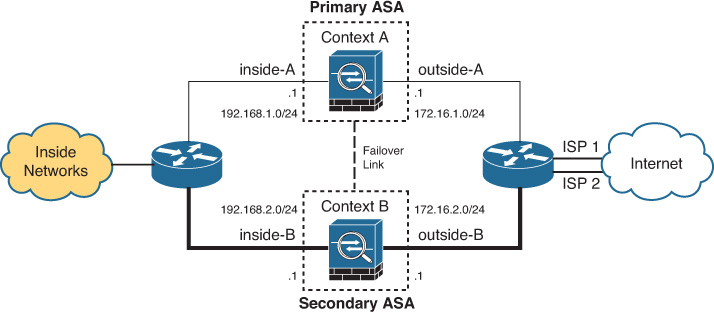
The problem arises when an inside host opens an outbound connection through the inside-A and outside-A interfaces of context A, but the response comes back to the outside-B interface of context B. Since context B has no stateful entry for the original outbound connection, the ASA drops the response. With Active/Active failover, ASR groups solve this problem by consulting a shared connection table for all interfaces within a group and redirecting an asymmetrically routed packet to a correct context for processing. Place inside-A and inside-B interfaces in ASR group 1, and similarly assign outside-A and outside-B to ASR group 2. Never assign a transit interface pair in the same context, such as inside-A and outside-A, to the same ASR group, because this leads to forwarding loops. ASR group functionality requires stateful failover, and ICMP connection information replicates automatically when this feature is enabled.
After you add interfaces to the respective ASR groups as just noted, the following sequence occurs for asymmetrically routed transit packets:
1. An inside endpoint sends a TCP SYN packet toward the Internet through the inside router.
2. The inside router load-balances that packet to the inside-A interface of context A.
3. Active context A on the primary ASA creates a stateful connection entry and sends this packet through the outside-A interface to the outside router. The stateful connection entry replicates to standby context A on the secondary device.
4. The outside router transmits the packet to the Internet using one of the available ISP links.
5. The outside router receives a TCP SYN ACK packet in response and load-balances it toward the outside-B interface of context B.
6. Active context B on the secondary ASA does not find a stateful connection entry to match the incoming packet, so it consults all local contexts that have interfaces in the same ASR group 2 as outside-B. Because the outside-A interface in standby context A belongs to this group, ASA finds the associated stateful connection entry for the original flow. Context A is active on the primary unit, so the secondary ASA rewrites the destination MAC address of the incoming TCP SYN ACK packet to be the active MAC address of the outside-A interface and reinjects the modified frame into the outside-A subnet.
7. Active context A on the primary ASA receives the reinjected TCP SYN ACK packet, matches it to a connection entry, and passes it on to the inside router.
8. The inside router delivers the response to the initiator.
9. If the inside router load-balances the subsequent TCP ACK packet from the inside host to the active inside-B interface on the secondary unit, steps similar to 6 and 7 occur to direct the packet through the active inside-A interface on the primary ASA.
With a relatively slow stateful failover link, the connection update may not reach a standby context on the peer unit before an asymmetrical packet arrives. If this were to occur in the preceding example, the secondary ASA would not find a matching stateful connection entry in Step 6 and would drop the asymmetrically received TCP SYN ACK packet instead of redirecting it to active context A on the primary unit. This highlights the importance of using a low-latency stateful link when Active/Active failover with ASR groups is enabled. Note that ASR groups are not available with Active/Standby failover.
Failover Health Monitoring
An ASA in the failover pair constantly monitors its local hardware state for problems and considers itself failed when at least one of the following conditions occurs:
![]() One of the internal interfaces goes down
One of the internal interfaces goes down
![]() An interface expansion card fails
An interface expansion card fails
![]() An IPS, CSC, or CX application module fails
An IPS, CSC, or CX application module fails
When an active unit detects a local failure, it checks if its standby peer is more operationally healthy. If that is the case, the active unit marks itself as failed and requests the standby to take over the active role. If a standby unit detects a local failure, it simply marks itself as failed.
Each unit uses the failover control link to report its own operational health and monitor the health of its peer by exchanging periodic keepalive messages. The default unit poll time interval for these messages is 1 second. By default, an ASA allows the hold time of 15 seconds without any keepalive messages from its failover peer before taking the following steps:
1. Count the number of locally configured interfaces in the link up state.
2. On each data interface with a standby address, generate a failover message toward the peer and report the local number of healthy interfaces.
If a failover unit receives such a message from its peer, it responds back on each interface with the local count of the operational interfaces. Based on this exchange, the failover members determine the next steps in the following manner:
![]() If the peer responds on at least one data interface and the active unit reports more operational interfaces than the standby, no switchover occurs.
If the peer responds on at least one data interface and the active unit reports more operational interfaces than the standby, no switchover occurs.
![]() If the peer responds on at least one data interface and the active unit reports fewer operational interfaces than the standby, a switchover occurs.
If the peer responds on at least one data interface and the active unit reports fewer operational interfaces than the standby, a switchover occurs.
![]() If the peer does not respond at all, a switchover occurs.
If the peer does not respond at all, a switchover occurs.
![]() In all these cases, failover becomes disabled until the failover control link communication resumes. Until then, no switchover occurs even if the active unit becomes less operationally healthy than the standby.
In all these cases, failover becomes disabled until the failover control link communication resumes. Until then, no switchover occurs even if the active unit becomes less operationally healthy than the standby.
If the peer responds on the failover control interface, no switchover occurs and failover remains enabled. This highlights the importance of ensuring the failover control link availability at all times to support proper operation of the failover pair.
In addition to the basic hardware checks, each failover unit can monitor the state of its data interfaces. Similarly to the keepalive messages on the failover control link, peer ASA devices exchange periodic messages on all named data interfaces that are configured with standby IP addresses and have interface monitoring enabled. Only physical interfaces are monitored by default, but you can monitor subinterfaces, redundant interfaces, and EtherChannel links on ASAs or VLAN interfaces on ASA Services Modules by adding appropriate monitor-interface commands. Consider these guidelines when choosing which interfaces to monitor:
![]() Interface monitoring generates periodic bursts of packets and consumes additional processing resources. With the maximum number of VLAN interfaces on an ASA Services Module, each peer generates 1024 interface keepalive packets every few seconds.
Interface monitoring generates periodic bursts of packets and consumes additional processing resources. With the maximum number of VLAN interfaces on an ASA Services Module, each peer generates 1024 interface keepalive packets every few seconds.
![]() If you share an interface between multiple security contexts, enable monitoring in only one of these contexts.
If you share an interface between multiple security contexts, enable monitoring in only one of these contexts.
![]() Monitoring a single subinterface on a VLAN trunk detects a failover of the underlying physical interface.
Monitoring a single subinterface on a VLAN trunk detects a failover of the underlying physical interface.
![]() Failover monitors redundant interfaces and EtherChannel links at the logical level, so it does not detect individual member link failures. These types of interfaces go down only when all of the underlying physical ports fail. If you want to bring an EtherChannel link down and force failover to mark it as failed after a certain number of member interface failures, use the port-channel min-bundle command.
Failover monitors redundant interfaces and EtherChannel links at the logical level, so it does not detect individual member link failures. These types of interfaces go down only when all of the underlying physical ports fail. If you want to bring an EtherChannel link down and force failover to mark it as failed after a certain number of member interface failures, use the port-channel min-bundle command.
The default interface poll and hold times are 5 and 25 seconds, respectively. When an ASA does not receive any keepalive messages from its peer on a monitored interface for 1/2 of the configured interface hold time, it performs the following tests to determine whether the local interface is operationally healthy:
1. If the local interface link state on an ASA or the VLAN on an ASA Services Module is down, mark it as failed and stop the test.
2. For 1/16 of the interface hold time, check if any incoming packets arrive on the interface. If so, mark the interface as healthy and stop the test.
3. Generate an ARP request for the two most recently used entries in the local cache. For 1/4 of the interface hold time, check if any incoming packets arrive on the interface. If so, mark the interface as healthy and stop the test.
4. Generate an IP broadcast ping out of the interface. For 1/8 of the interface hold time, check if any incoming packets arrive on the interface. If so, mark the interface as healthy and stop the test.
5. If no incoming packets arrived on the local interface during the test, check if the same interface on the peer unit is healthy. If so, mark the interface as failed.
By default, a switchover occurs when at least one interface on the active unit or within an active failover group fails. Use the failover interface-policy command with Active/Standby failover or the interface-policy command under a failover group with Active/Active failover to change the threshold to a higher value. Specify how many interfaces on the unit or in a failover group must fail before a switchover should be attempted. Express this threshold as a percentage of all monitored interfaces. No switchover occurs if the standby unit has fewer operationally healthy interfaces, and failover does not consider nonmonitored interfaces in this comparison.
Lower the unit and interface poll and hold times to speed up dead-peer detection and interface testing. Keep in mind that lower timers typically increase the frequency of keepalive packets, and the probability of such packets getting lost during brief network congestions increases as well. Because the reduced hold times allow a much smaller window to recover from lost keepalives or to successfully complete interface testing, undesired failover events are possible in this configuration. You need to balance the need for a quicker traffic recovery against your network tolerance toward false positive failover events.
State and Role Transition
When you configure an ASA for failover or when an existing ASA failover peer boots up, the device goes through the following steps before enabling its data interfaces:
1. Monitor the failover control link for keepalive packets from an active peer for at least 50 seconds in the Negotiation state. This delay prevents the new unit from going active in the presence of an active ASA while STP is converging on the failover control interface. Always enable STP PortFast on failover control link ports from the switch side to speed up the detection of an active failover peer.
2. If the unit detects an active peer during the negotiation phase, it immediately starts the synchronization process in order to assume the standby state for the entire system in Active/Standby or the failover groups in Active/Active. The configuration synchronization happens during the Config Sync phase, and the stateful information synchronizes during the Bulk Sync phase if stateful failover is enabled. It is normal for data interfaces on the new unit to transition through a down state during this process. After going through these states, a healthy unit programs its data interfaces with the standby MAC and IP addresses and transitions to the Standby Ready state. If the standby unit fails to successfully complete the failover negotiation process with the active peer due to a hardware compatibility check or any other reason, it remains in the Cold Standby state until the problem gets resolved.
3. If the ASA detects no existing active peer during the negotiation state, it progresses through Just Active, Active Drain, Active Applying Config, and Active Config Applied states, which prepare the various components of the failover subsystem to forward transit traffic and program the data interfaces with active MAC and IP addresses. When that process completes, the unit assumes the Active state.
When health monitoring determines that the particular unit is less operationally healthy than its peer, the local peer transitions to the Failed state until the problem gets resolved. The more operationally healthy standby unit transitions to the Active state. Only a unit in the Standby Ready state can take over the active forwarding role.
If either failover peer loses failover control link connectivity to the other member, it transitions itself to the Disabled state until such connectivity resumes. In a rare situation where all communication between the failover peers ceases and both units erroneously transition to the active role, the primary unit always remains active after the failover control link communication restores. The secondary active unit always stands down and transitions to standby when it detects the primary active peer.
In Active/Standby failover, there is no concept of preemption. If a primary active unit fails or reloads and the secondary unit takes over, the primary peer will not automatically become active even when it becomes operational healthy again. The primary unit takes over the active role only when the secondary unit fails or you perform a manual switchover. In Active/Active failover, you can optionally configure either failover group for preemption by its respective owner with the preempt command. You can also configure each unit to wait for a predefined time interval before becoming active for its assigned group after transitioning to the Standby Ready state.
Configuring Failover
Always start failover configuration on the primary unit. If you have an existing ASA in your network, you can configure it as the primary failover unit without losing any of the configuration. You should still schedule a maintenance window for deploying failover, because data interfaces shut down while the sole failover unit transitions to the active state. The following prerequisites apply to the failover configuration process:
![]() Make sure that both failover peers have an appropriate license. Cisco ASA 5505, ASA 5510, and ASA 5512-X appliances require a Security Plus license for failover.
Make sure that both failover peers have an appropriate license. Cisco ASA 5505, ASA 5510, and ASA 5512-X appliances require a Security Plus license for failover.
![]() Pick one or more separate physical or VLAN interfaces for the failover control and optional stateful links. Make sure that these physical interfaces are enabled either at the CLI by using the no shutdown command or in ASDM by checking the Enable Interface check box in the Edit dialog box (navigate to Configuration > Device Setup > Interfaces, select the interface, and click Edit). When possible, preconfigure redundant interfaces on top of the physical links for extra protection of the failover pair. Use direct back-to-back connections between the peers for the failover interfaces. If you intend to use VLAN subinterfaces on ASAs, make sure to preconfigure them in advance.
Pick one or more separate physical or VLAN interfaces for the failover control and optional stateful links. Make sure that these physical interfaces are enabled either at the CLI by using the no shutdown command or in ASDM by checking the Enable Interface check box in the Edit dialog box (navigate to Configuration > Device Setup > Interfaces, select the interface, and click Edit). When possible, preconfigure redundant interfaces on top of the physical links for extra protection of the failover pair. Use direct back-to-back connections between the peers for the failover interfaces. If you intend to use VLAN subinterfaces on ASAs, make sure to preconfigure them in advance.
![]() Identify an isolated IP subnet for the failover control and stateful links. This subnet must accommodate at least two devices. It cannot overlap with any data interfaces or NAT configuration policies. When you choose to pass stateful information over the failover control link, you need only one subnet.
Identify an isolated IP subnet for the failover control and stateful links. This subnet must accommodate at least two devices. It cannot overlap with any data interfaces or NAT configuration policies. When you choose to pass stateful information over the failover control link, you need only one subnet.
![]() Identify a standby IP address for each data interface that you intend to monitor.
Identify a standby IP address for each data interface that you intend to monitor.
![]() If you intend to configure virtual MAC addresses, identify virtual active and standby values for each data interface.
If you intend to configure virtual MAC addresses, identify virtual active and standby values for each data interface.
![]() Choose between Active/Standby and Active/Active failover. Keep in mind that Active/Active failover requires multiple-context mode. You need to switch both failover peers to the correct context mode independently; this setting does not synchronize through failover.
Choose between Active/Standby and Active/Active failover. Keep in mind that Active/Active failover requires multiple-context mode. You need to switch both failover peers to the correct context mode independently; this setting does not synchronize through failover.
![]() Make sure that the corresponding data interfaces of the failover peers connect to the same network segments with Layer 2 adjacency. If you are adding an ASA to join the existing unit in a failover pair, make sure that the new device does not have any preexisting interface configuration. Use the clear configure interface command to clear it.
Make sure that the corresponding data interfaces of the failover peers connect to the same network segments with Layer 2 adjacency. If you are adding an ASA to join the existing unit in a failover pair, make sure that the new device does not have any preexisting interface configuration. Use the clear configure interface command to clear it.
Basic Failover Settings
After you complete the prerequisites, follow these steps to configure basic failover settings through ASDM:
1. Connect to the designated primary failover ASA and navigate to the Setup tab under Configuration > Device Management > High Availability and Scalability > Failover. When operating in multiple-context mode, you must perform this step under the system context. Figure 16-7 shows the Setup tab with sample configuration parameters for the steps that follow.

2. In the LAN Failover area, configure the failover control link and assign a unit role:
a. From the Interface drop-down menu, choose an available and unconfigured physical or VLAN interface. You can use a VLAN subinterface on appliances as long as the underlying physical interface is available and unconfigured. ASA clears any other configuration under the selected interface. In this case, the GigabitEthernet0/2 interface is used.
b. In the Logical Name field, enter a logical name for the failover control link, using the same constrains as any interface. FailoverControl is used as the link name.
c. In the respective fields, specify the active IP and standby IP addresses and the subnet mask for the failover control link. The subnet must not overlap with any other configured interfaces. The primary unit in the failover pair always uses the active IP address on this link. Similarly, the secondary unit employs the standby IP address. These addresses are never swapped on switchover events. The example uses 192.168.100.1 for the primary address and 192.168.100.2 for the secondary address on the 192.168.100.0/24 subnet.
d. Choose the Preferred Role setting for this unit. This designation never changes during switchover events. Always configure the primary unit first, as shown in this example.
3. In the State Failover area, configure the optional stateful failover link and choose what additional information the active unit should replicate:
a. From the Interface drop-down menu, choose an available and unconfigured physical interface, similarly to Step 2a. You can use a second subinterface on the same physical interface that already has the failover control link subinterface. You can also choose the same interface as the failover control link to carry stateful information. Figure 16-7 uses the separate GigabitEthernet0/3 interface.
b. In the Logical Name field, enter a logical name for the stateful link, similarly to Step 2b. This option is not available if you use the same interface for failover control and stateful links. FailoverState is used as the stateful link name in this example.
c. In the respective fields, specify the active IP and standby IP addresses and the subnet mask, similarly to Step 2c. This option is not available if you use the same interface for failover control and stateful links. If you choose to configure a separate stateful link, the subnet must not overlap with any other configured interfaces, including the failover control link. 192.168.101.1 is used for the primary address and 192.168.101.2 for the secondary address on the 192.168.101.0/24 subnet.
d. Check the Enable HTTP Replication check box if you want the standby unit to receive state information from the active unit for HTTP connections over TCP port 80. Because the majority of HTTP connections are very short-lived, keep this option disabled to increase connection setup performance of the failover pair. Only enable this option when handling business-critical HTTP connections or using the ASR groups feature with Active/Active failover. In this example, HTTP state replication is enabled.
4. Enable optional failover control and stateful link encryption by specifying the Shared Key or IPsec Preshared Key values. Keep the Use 32 Hexadecimal Character Key check box unchecked if you want to specify the basic encryption key as a free string of letters, numbers, and punctuation characters. The IPsec-based failover link encryption is a more secure and preferred option. The example in Figure 16-7 enables an internal IPsec tunnel to protect both failover control and stateful links with the key value of cisco. Notice that the key value does not appear in the input field, but it is stored as clear text in the ASA configuration unless you enable the Master Passphrase feature under the Configuration > Device Management > Advanced > Master Passphrase tab in ASDM.
5. Check the Enable Failover check box to enable failover operation. This new ASA failover pair member goes through the negotiation phase before transitioning to the active state. This results in transit traffic interruption for about 50 seconds.
6. When the primary ASA assumes the active role, proceed with similar steps to configure the secondary unit. Keep in mind that the value of all input fields should remain the same with the exception of the Preferred Role option in Step 2d; you must choose Secondary for the other failover peer. As an alternative to using ASDM, you can also obtain the show running-config failover output from the primary unit, change the failover lan unit primary line to failover lan unit secondary, and copy the resulting set of commands to the secondary ASA. Make sure to configure and enable the failover control and stateful physical interfaces on the secondary unit before performing this step.
Example 16-5 and Example 16-6 illustrate the basic failover configuration commands that correspond to the previous ASDM steps for the primary and secondary units, respectively.
Example 16-5 Basic Failover Configuration on Primary Unit
failover
failover lan unit primary
failover lan interface FailoverControl GigabitEthernet0/2
failover replication http
failover link FailoverState GigabitEthernet0/3
failover interface ip FailoverControl 192.168.100.1 255.255.255.0 standby
192.168.100.2
failover interface ip FailoverState 192.168.101.1 255.255.255.0 standby 192.168.101.2
failover ipsec pre-shared-key *****
Example 16-6 Basic Failover Configuration on Secondary Unit
failover
failover lan unit secondary
failover lan interface FailoverControl GigabitEthernet0/2
failover replication http
failover link FailoverState GigabitEthernet0/3
failover interface ip FailoverControl 192.168.100.1 255.255.255.0 standby
192.168.100.2
failover interface ip FailoverState 192.168.101.1 255.255.255.0 standby 192.168.101.2
failover ipsec pre-shared-key *****
Data Interface Configuration
To configure standby IP addresses on all monitored data interfaces with ASDM, use the Setup tab under Configuration > Device Management > High Availability and Scalability > Failover (previously shown in Figure 16-7). When running in multiple-context mode, you must do this from each respective security context. Figure 16-8 illustrates an example of data interface configuration in single-context mode:
1. For each interface that you intend to monitor or access from the network on the standby unit, fill out the Standby IP Address field. The standby IP address must reside on the same subnet as the configured active IP address. This address must also not be used by any other device on the same network. Figure 16-8 assigns standby addresses to both the inside and outside interfaces.
2. Check the Monitored check box for each interface that you want the failover subsystem to monitor. Refer to the earlier “Failover Health Monitoring” section for guidelines on data interface monitoring. In Figure 16-8, failover monitors both data interfaces.

If desired, you can configure active and standby virtual MAC addresses for data interfaces. Refer to the “Data Interface Addressing” section earlier in the chapter for a detailed discussion of why virtual MAC addresses are useful with failover. There are several ways to accomplish this task in ASDM:
Use the MAC Addresses tab under Configuration > Device Management > High Availability and Scalability > Failover in the system context. You can only use this method to configure physical interfaces on ASAs and VLAN interfaces on the ASA Services Module. Figure 16-9 illustrates how to configure active and standby virtual MAC addresses on GigabitEthernet0/0 and 0/1 interfaces.
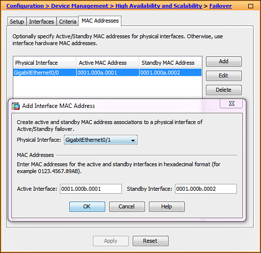
Use the Configuration > Device Setup > Interfaces panel in each context or when running in single-context mode. For each logical data interface, select it, click Edit, and choose the Advanced tab to configure virtual active and standby MAC addresses, as shown in Figure 16-10. Interface-specific MAC address configuration takes precedence over the failover MAC address settings under the physical interfaces.

Failover Policies and Timers
To edit the default failover interface monitoring policies and adjust unit and interface poll and hold timers in ASDM, navigate to Configuration > Device Management > High Availability and Scalability > Failover in the system context and click the Criteria tab, shown in Figure 16-11 with some sample values.

Configure the following optional parameters on this tab:
In the Interface Policy area, specify how many interfaces must fail before the active unit is considered operationally unhealthy. Either specify an absolute value (after clicking the top radio button) or a percentage of the total number of configured data interfaces (after clicking the bottom radio button). Figure 16-11 shows the default policy where the active unit attempts a switchover after a single interface failure.
In the Failover Poll Times area, adjust the following timers, which were discussed earlier in the “Failover Health Monitoring” section:
![]() Unit Failover: The number of times each unit generates keepalive messages on the failover control link. Specify a value from 200 milliseconds to 15 seconds. In the example in Figure 16-11, keepalive messages are generated every 500 milliseconds.
Unit Failover: The number of times each unit generates keepalive messages on the failover control link. Specify a value from 200 milliseconds to 15 seconds. In the example in Figure 16-11, keepalive messages are generated every 500 milliseconds.
![]() Unit Hold Time: The amount of time each unit waits before probing its peer on all data interfaces in the absence of failover keepalive messages on the control link. Specify a value from 800 milliseconds to 45 seconds, but make sure that it is at least three times the configured unit poll time. Figure 16-11 shows a unit hold time of 3 seconds.
Unit Hold Time: The amount of time each unit waits before probing its peer on all data interfaces in the absence of failover keepalive messages on the control link. Specify a value from 800 milliseconds to 45 seconds, but make sure that it is at least three times the configured unit poll time. Figure 16-11 shows a unit hold time of 3 seconds.
![]() Monitored Interfaces: The number of times each unit generates keepalive messages on its monitored links. Specify a value from 500 milliseconds to 15 seconds. Figure 16-11 shows an interface poll time of 2 seconds.
Monitored Interfaces: The number of times each unit generates keepalive messages on its monitored links. Specify a value from 500 milliseconds to 15 seconds. Figure 16-11 shows an interface poll time of 2 seconds.
![]() Interface Hold Time: The amount of time each unit tests a monitored interface that is not receiving keepalive messages from the peer before declaring it failed. Specify a value from 5 to 75 seconds, but make sure it is at least five times the interface poll time. Figure 16-11 shows an interface hold time of 10 seconds.
Interface Hold Time: The amount of time each unit tests a monitored interface that is not receiving keepalive messages from the peer before declaring it failed. Specify a value from 5 to 75 seconds, but make sure it is at least five times the interface poll time. Figure 16-11 shows an interface hold time of 10 seconds.
Example 16-7 shows a command-line configuration that corresponds to the sample ASDM configuration screen shown in Figure 16-11.
Example 16-7 Failover Policy and Timer Configuration
failover polltime unit msec 500 holdtime 3
failover polltime interface 2 holdtime 10
These timers apply globally in Active/Standby and Active/Active failover, but you can also override the interface-specific policies and timers for each failover group, as discussed in the next section.
Active/Active Failover
When using Active/Active failover, configure failover groups in ASDM by clicking the Active/Active tab under Configuration > Device Management > High Availability and Scalability > Failover in the system context. Click Add to configure a new group or click Edit to change an existing one. You can configure up to two failover groups, and both of them must be active on the same unit in order to make changes. Figure 16-12 shows a sample configuration dialog box for failover group 1.
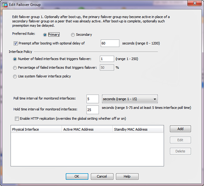
Configure the following parameters in this dialog box:
![]() For the Preferred Role option, choose Primary or Secondary to indicate which unit will own the group by default. This example assigns ownership of failover group 1 to the primary unit.
For the Preferred Role option, choose Primary or Secondary to indicate which unit will own the group by default. This example assigns ownership of failover group 1 to the primary unit.
![]() Check the Preempt After Booting with the Optional Delay Of check box if you want the preferred owner unit to assume the active role for this group upon booting up or transitioning from a failed to a healthy state. Specify the optional delay value for this operation. By default, preemption occurs immediately when enabled. In Figure 16-12, the primary unit transitions to the active role for group 1 after 60 seconds of remaining operationally healthy.
Check the Preempt After Booting with the Optional Delay Of check box if you want the preferred owner unit to assume the active role for this group upon booting up or transitioning from a failed to a healthy state. Specify the optional delay value for this operation. By default, preemption occurs immediately when enabled. In Figure 16-12, the primary unit transitions to the active role for group 1 after 60 seconds of remaining operationally healthy.
![]() In the Interface Policy area, override certain global failover parameters on a per-group basis. In Figure 16-12, the following changes from the global settings apply to all contexts in failover group 1:
In the Interface Policy area, override certain global failover parameters on a per-group basis. In Figure 16-12, the following changes from the global settings apply to all contexts in failover group 1:
![]() Consider the active unit for this group failed if at least one monitored interface between all contexts in this group fails the health test.
Consider the active unit for this group failed if at least one monitored interface between all contexts in this group fails the health test.
![]() Generate failover keepalive packets on all monitored interfaces every 5 seconds.
Generate failover keepalive packets on all monitored interfaces every 5 seconds.
![]() Consider the monitored interface failed if none of the health checks complete successfully after 25 seconds from missing the first periodic interface keepalive packet.
Consider the monitored interface failed if none of the health checks complete successfully after 25 seconds from missing the first periodic interface keepalive packet.
![]() Disable stateful replication for HTTP connections over TCP port 80 in all contexts in this failover group.
Disable stateful replication for HTTP connections over TCP port 80 in all contexts in this failover group.
![]() In the table at the bottom of the dialog box, configure MAC addresses for physical interfaces that belong to contexts in this failover group. Rely on the mac-address auto command or configure virtual MAC addresses under the respective contexts instead.
In the table at the bottom of the dialog box, configure MAC addresses for physical interfaces that belong to contexts in this failover group. Rely on the mac-address auto command or configure virtual MAC addresses under the respective contexts instead.
Assign contexts to a particular failover group in ASDM by navigating to Configuration > Context Management > Security Contexts under the system context. When creating a new context with the Add button or changing an existing context with the Edit button, the Failover Group drop-down menu allows you to select group 1 or group 2 for each context. By default, all contexts appear in group 1. The unit must be active for both failover groups in order to change the assignment.
Example 16-8 shows a system context configuration with three contexts distributed between two failover groups in Active/Active failover. Failover group 1 configuration follows the ASDM settings in Figure 16-12 and contains contexts admin and A. Failover group 2 belongs to the secondary unit, inherits all failover parameters from the global configuration, and contains context B.
Example 16-8 System Context Configuration with Failover Groups
failover group 1
primary
preempt 60
interface-policy 1
failover polltime interface 5 holdtime 25
failover group 2
secondary
!
admin-context admin
context admin
allocate-interface Management0/0
config-url flash:/admin.cfg
join-failover-group 1
!
context A
allocate-interface GigabitEthernet1/0
allocate-interface GigabitEthernet1/1
config-url flash:/A.cfg
join-failover-group 1
!
context B
allocate-interface GigabitEthernet1/2
allocate-interface GigabitEthernet1/3
config-url flash:/B.cfg
join-failover-group 2
Assign interfaces to ASR groups in ASDM by navigating to Configuration > Device Setup > Routing > ASR Groups in each applicable context. When two or more interfaces in different contexts may receive asymmetrically routed traffic for each other, they need to belong to the same numeric ASR group. One ASR group can contain up to eight member interfaces across all contexts.
Example 16-9 and Example 16-10 show the interface configuration in contexts A and B respectively with ASR groups configured in Active/Active failover. These examples follow the scenario described earlier in the “Asymmetric Routing Groups” section and depicted in Figure 16-6.
Example 16-9 Context A Configuration with ASR Groups
interface GigabitEthernet1/0
nameif outside-A
security-level 0
ip address 172.16.1.1 255.255.255.0 standby 172.16.1.2
asr-group 2
!
interface GigabitEthernet1/1
nameif inside-A
security-level 100
ip address 192.168.1.1 255.255.255.0 standby 192.168.1.2
asr-group 1
Example 16-10 Context B Configuration with ASR Groups
interface GigabitEthernet1/2
nameif outside-B
security-level 0
ip address 172.16.2.1 255.255.255.0 standby 172.16.2.2
asr-group 2
!
interface GigabitEthernet1/3
nameif inside-B
security-level 100
ip address 192.168.2.1 255.255.255.0 standby 192.168.2.2
asr-group 1
Monitoring and Troubleshooting Failover
Use the show failover command to monitor the operational state of the failover subsystem. Example 16-11 illustrates sample output from a failover pair operating in Active/Standby mode. Among other data, this output contains the following:
![]() Status of failover control and stateful links
Status of failover control and stateful links
![]() Date and time of the last failover event
Date and time of the last failover event
![]() Operational state of both failover peers
Operational state of both failover peers
![]() Health status of all monitored data interfaces
Health status of all monitored data interfaces
Example 16-11 Monitoring Failover Status
asa# show failover
Failover On
Failover unit Primary
Failover LAN Interface: FailoverLink GigabitEthernet0/3 (up)
Unit Poll frequency 1 seconds, holdtime 15 seconds
Interface Poll frequency 5 seconds, holdtime 25 seconds
Interface Policy 1
Monitored Interfaces 2 of 160 maximum
Version: Ours 9.1(2)6, Mate 9.1(2)6
Last Failover at: 11:10:37 PDT Sep 21 2013
This host: Primary - Active
Active time: 186 (sec)
slot 0: ASA5520 hw/sw rev (1.1/9.1(2)6) status (Up Sys)
Interface outside (172.16.164.120): Normal
Interface inside (192.168.1.1): Normal
slot 1: ASA-SSM-20 hw/sw rev (1.0/7.0(2)E4) status (Up/Up)
IPS, 7.0(2)E4, Up
Other host: Secondary - Standby Ready
Active time: 0 (sec)
Interface outside (172.16.164.121): Normal
Interface inside (192.168.1.2): Normal
slot 1: ASA-SSM-20 hw/sw rev (1.0/7.0(2)E4) status (Up/Up)
IPS, 7.0(2)E4, Up
Stateful Failover Logical Update Statistics
Link : FailoverLink GigabitEthernet0/3 (up)
Stateful Obj xmit xerr rcv rerr
General 354 0 263 4
sys cmd 35 0 35 0
up time 0 0 0 0
RPC services 0 0 0 0
TCP conn 202 0 135 0
UDP conn 99 0 69 4
ARP tbl 16 0 22 0
Xlate_Timeout 0 0 0 0
IPv6 ND tbl 0 0 0 0
VPN IKEv1 SA 0 0 0 0
VPN IKEv1 P2 0 0 0 0
VPN IKEv2 SA 0 0 0 0
VPN IKEv2 P2 0 0 0 0
VPN CTCP upd 0 0 0 0
VPN SDI upd 0 0 0 0
VPN DHCP upd 0 0 0 0
SIP Session 0 0 0 0
Route Session 0 0 0 0
User-Identity 0 0 0 0
CTS SGTNAME 0 0 0 0
CTS PAC 0 0 0 0
TrustSec-SXP 0 0 0 0
IPv6 Route 0 0 0 0
Logical Update Queue Information
Cur Max Total
Recv Q: 0 24 1872
Xmit Q: 0 1 757
The xerr and rerr columns under the stateful failover counters refer to transmit and receive errors, which may increment when the stateful link or either failover peer is under heavy load. Use the debug fover fail command to troubleshoot such failover synchronization issues. Keep in mind that this command may generate a lot of output and increase the processing load on your ASA. Example 16-12 illustrates debug output from the standby unit where the ASA could not create a stateful connection entry for this flow. If you are systematically seeing such synchronization failures for some connections, contact Cisco TAC.
Example 16-12 Stateful Session Creation Failure on Standby ASA
Failed to create flow (dropped) for np/port/id/0/-1: 172.25.1.1/65086 - np/port/id/1/-1: 172.25.2.100/48799
The failover subsystem generates syslog messages at alerts level for important system events. Example 16-13 illustrates a message that indicates the secondary standby unit took over the active rule after losing all communication with the primary active ASA.
Example 16-13 Failover Event Syslog Message
%ASA-1-104001: (Secondary) Switching to ACTIVE - HELLO not heard from mate.
You can also leverage the show failover history command to investigate failover events. Example 16-14 shows sample output from the secondary ASA that corresponds to the message in Example 16-13. This output displays up to 20 past failover state transitions along with the associated timestamps and detailed reasons.
Example 16-14 Failover State Transition History
asa# show failover history
==========================================================================
From State To State Reason
==========================================================================
16:14:27 CDT Sep 19 2013
Standby Ready Just Active HELLO not heard from mate
16:14:27 CDT Sep 19 2013
Just Active Active Drain HELLO not heard from mate
16:14:27 CDT Sep 19 2013
Active Drain Active Applying Config HELLO not heard from mate
16:14:27 CDT Sep 19 2013
Active Applying Config Active Config Applied HELLO not heard from mate
16:14:27 CDT Sep 19 2013
Active Config Applied Active HELLO not heard from mate
==========================================================================
Active/Standby Failover Deployment Scenario
Figure 16-13 illustrates a sample network topology for Active/Standby failover deployment. Assuming that the physical interface connections are already in place, configure failover with the following considerations:
![]() Replicate stateful information for all non-HTTP connections
Replicate stateful information for all non-HTTP connections
![]() Use a shared redundant interface for the failover control and stateful links
Use a shared redundant interface for the failover control and stateful links
![]() Achieve the fastest possible switchover even at the risk of false positives
Achieve the fastest possible switchover even at the risk of false positives
![]() Protect network stability during device replacements with virtual MAC addresses
Protect network stability during device replacements with virtual MAC addresses
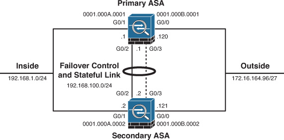
Follow these steps to configure the primary unit using the command-line interface:
1. Configure GigabitEthernet0/2 and GigabitEthernet0/3 to form a redundant interface for the failover control and stateful link:
asa(config)# interface GigabitEthernet 0/2
asa(config-if)# no shutdown
asa(config-if)# interface GigabitEthernet 0/3
asa(config-if)# no shutdown
asa(config-if)# interface Redundant 1
asa(config-if)# member-interface GigabitEthernet 0/2
INFO: security-level and IP address are cleared on GigabitEthernet0/2.
asa(config-if)# member-interface GigabitEthernet 0/3
INFO: security-level and IP address are cleared on GigabitEthernet0/3.
2. Set the unit role:
asa(config)# failover lan unit primary
3. Configure the Redundant1 interface as the failover control link and set its IP addresses for both primary and secondary units:
asa(config)# failover lan interface FailoverLink Redundant1
INFO: Non-failover interface config is cleared on Redundant1 and its sub-interfaces
asa(config)# failover interface ip FailoverLink 192.168.100.1 255.255.255.0 standby 192.168.100.2
The failover subsystem automatically removes all other configuration and adds a description on the failover control link interface. You cannot make changes to this interface while failover is enabled.
4. Configure the Redundant1 interface as the stateful failover link. Because failover control and stateful links share the same interface, you only need to specify the same name as in the previous step; you do not need to configure separate IP addresses:
asa(config)# failover link FailoverLink
Because the failover control and stateful link interfaces use a direct back-to-back connection between the ASA appliances, you do not have to enable data encryption on this interface.
5. Configure the unit to generate keepalive messages on the failover control link every 200 ms. The system automatically sets the hold time to the minimum possible value of 800 ms.
asa(config)# failover polltime msec 200
INFO: Failover unit holdtime is set to 800 milliseconds
These aggressive timers ensure that the standby unit can detect a failure of the peer ASA and take over the active role within 800 ms; this is called sub-second failover. Keep in mind that false positive switchovers may occur under heavy load, because the peers have limited time to recover from missed keepalive packets.
6. Configure the ASA to exchange data interface keepalive messages every 500 ms. The system sets the interface hold time to the minimum value of 5 seconds.
asa(config)# failover polltime interface msec 500
INFO: Failover interface holdtime is set to 5 seconds
These settings allow an ASA to complete the health check of a monitored interface within 5 seconds of missing a keepalive packet from the peer. This may also cause false positive switchovers when the traffic level on a monitored interface is relatively low.
7. Configure the data interfaces:
asa(config)# interface GigabitEthernet 0/0
asa(config-if)# nameif outside
INFO: Security level for "outside" set to 0 by default.
asa(config-if)# no shutdown
asa(config-if)# mac-address 0001.000B.0001 standby 0001.000B.0002
asa(config-if)# ip address 172.16.164.120 255.255.255.224 standby 172.16.164.121
asa(config-if)# interface GigabitEthernet 0/1
asa(config-if)# nameif inside
INFO: Security level for "inside" set to 100 by default.
asa(config-if)# no shutdown
asa(config-if)# mac-address 0001.000A.0001 standby 0001.000A.0002
asa(config-if)# ip address 192.168.1.1 255.255.255.0 standby 192.168.1.2
8. Enable failover. The primary unit takes about 50 seconds to go through the negotiation phase and transition to the active role.
asa(config)# failover
No Active mate detected
9. Use the show failover command to confirm that the primary unit is active:
asa# show failover | include host
This host: Primary - Active
Other host: Secondary - Not Detected
After configuring the primary ASA, follow these steps to bring the secondary unit into the failover pair:
10. Configure GigabitEthernet0/2 and GigabitEthernet0/3 to form a redundant interface for the failover control and stateful link:
asa(config)# interface GigabitEthernet 0/2
asa(config-if)# no shutdown
asa(config-if)# interface GigabitEthernet 0/3
asa(config-if)# no shutdown
asa(config-if)# interface Redundant 1
asa(config-if)# member-interface GigabitEthernet 0/2
INFO: security-level and IP address are cleared on GigabitEthernet0/2.
asa(config-if)# member-interface GigabitEthernet 0/3
INFO: security-level and IP address are cleared on GigabitEthernet0/3.
11. Set the unit role:
asa(config)# failover lan unit secondary
12. Configure Redundant1 interface as the failover control and stateful link with the same IP addresses as on the primary unit:
asa(config)# failover lan interface FailoverLink Redundant1
INFO: Non-failover interface config is cleared on Redundant1 and its sub-interfaces
asa(config)# failover interface ip FailoverLink 192.168.100.1 255.255.255.0 standby 192.168.100.2
asa(config)# failover link FailoverLink
13. Enable failover. The secondary unit should detect the primary active peer right away and synchronize the rest of the configuration, including the failover timers.
asa(config)# failover
Detected an Active mate
Beginning configuration replication from mate.
End configuration replication from mate.
14. Use the show failover command to confirm that the secondary unit is in the standby read state:
asa(config)# show failover | include host
This host: Secondary - Standby Ready
Other host: Primary - Active
Example 16-15 shows the complete data interface and failover configuration of the primary unit. The secondary unit has the same configuration with the exception of the failover lan unit secondary command.
Example 16-15 Complete Failover Configuration on Primary
interface GigabitEthernet0/0
mac-address 0001.000B.0001 standby 0001.000B.0002
nameif outside
security-level 0
ip address 172.16.164.120 255.255.255.224 standby 172.16.164.121
!
interface GigabitEthernet0/1
mac-address 0001.000A.0001 standby 0001.000A.0002
nameif inside
security-level 100
ip address 192.168.1.1 255.255.255.0 standby 192.168.1.2
!
interface GigabitEthernet0/2
!
interface GigabitEthernet0/3
!
interface Redundant1
description LAN Failover Interface
member-interface GigabitEthernet0/2
member-interface GigabitEthernet0/3
!
failover
failover lan unit primary
failover lan interface FailoverLink Redundant1
failover polltime unit msec 200 holdtime msec 800
failover polltime interface msec 500 holdtime 5
failover link FailoverLink Redundant1
failover interface ip failover 192.168.100.1 255.255.255.0 standby 192.168.100.2
Clustering
Use the Cisco ASA clustering feature to combine up to 16 supported appliances into a single traffic processing system. Unlike in failover, each unit of an ASA cluster actively forwards transit traffic in both the single- and multiple-context modes; you do not need to artificially separate transit traffic as with Active/Active failover. Adjacent switches and routers statelessly load-balance traffic between available cluster members via a cluster-spanned EtherChannel or IP routing. A cluster internally compensates for asymmetrically received traffic, so different units may receive packets that belong to the same connection. Aside from that important advantage, clustering has many similarities with failover:
![]() Stateful connection redundancy: Any cluster member can fail at any given time without impacting transit traffic or disrupting other cluster units. Each unit always maintains a backup of each stateful connection entry on a different physical ASA. A cluster remains operational when two or more members fail at the same time, but some connections may have to reestablish.
Stateful connection redundancy: Any cluster member can fail at any given time without impacting transit traffic or disrupting other cluster units. Each unit always maintains a backup of each stateful connection entry on a different physical ASA. A cluster remains operational when two or more members fail at the same time, but some connections may have to reestablish.
![]() Centralized management: You configure and monitor the entire cluster from a single member. The configuration automatically replicates to all other units.
Centralized management: You configure and monitor the entire cluster from a single member. The configuration automatically replicates to all other units.
![]() Zero Downtime upgrades: Cluster members continue to exchange information when running mismatched software images, so you can perform software upgrades without having to schedule downtime.
Zero Downtime upgrades: Cluster members continue to exchange information when running mismatched software images, so you can perform software upgrades without having to schedule downtime.
![]() License aggregation: Supported licensed features and capacities from all cluster members aggregate into a combined cluster license, so you can maximize the efficiency of your investment.
License aggregation: Supported licensed features and capacities from all cluster members aggregate into a combined cluster license, so you can maximize the efficiency of your investment.
Deploy clustering instead of failover when the design goals include both scalability and redundancy and your proposed ASA platforms support clustering. For all intents and purposes, you can view a cluster of ASAs as a single large firewall with the pay-as-you-grow capability.
Unit Roles and Functions in Clustering
Unlike with failover, you do not have to make any special role designations when creating a cluster. All operational cluster members forward traffic at all times, but each of them plays one or more dynamic roles.
Master and Slave Units
An ASA cluster elects one member as the master; all other members become slaves. Similarly to failover, you would typically configure clustering on one ASA and add other units later. That first unit becomes the master and remains in this role until it reloads or fails; you can also manually transition another unit into the master role with the cluster master unit command. The master unit performs the following functions in addition to regular traffic forwarding:
![]() Cluster configuration: You must always configure the cluster from the master unit. Slave units do not allow configuration changes aside from a basic set of the clustering bootstrap commands.
Cluster configuration: You must always configure the cluster from the master unit. Slave units do not allow configuration changes aside from a basic set of the clustering bootstrap commands.
![]() Main cluster IP address ownership: The master unit always receives any traffic destined to the virtual cluster IP addresses on all data and management interfaces. This allows you to consistently connect to the current unit for cluster configuration and monitoring.
Main cluster IP address ownership: The master unit always receives any traffic destined to the virtual cluster IP addresses on all data and management interfaces. This allows you to consistently connect to the current unit for cluster configuration and monitoring.
![]() Centralized connection handling: Certain features and functions require processing on the master unit. These include cluster-wide network infrastructure protocols, such as IGMP or PIM, or application-inspected connections, such as TFTP. Slaves always redirect incoming packets for such connections to the master unit. The “Centralized Features” section later in this chapter provides a complete list of all centralized traffic.
Centralized connection handling: Certain features and functions require processing on the master unit. These include cluster-wide network infrastructure protocols, such as IGMP or PIM, or application-inspected connections, such as TFTP. Slaves always redirect incoming packets for such connections to the master unit. The “Centralized Features” section later in this chapter provides a complete list of all centralized traffic.
All management connections and some centralized connections must reestablish upon master failure. Regular connections maintained by the master unit survive its failure as in the case of any other cluster member.
Flow Owner
A single cluster member must process all packets that belong to a single connection. This ensures symmetry for proper state tracking. For each connection, one unit in the cluster becomes the flow owner. Each cluster member may own some flows. Typically, the unit which received the first packet for a connection becomes its owner. If the original owner fails while a connection is still active, another unit assumes the ownership of that flow. Typically, any unit receiving a packet for an existing connection with no owner becomes its flow owner. A flow owner always maintains the full stateful connection entry.
Flow Director
The concept of a flow director is central to the high availability aspect of clustering. For each connection, the flow director always maintains the backup stateful information record. A flow owner periodically updates the flow director on the connection state. Other cluster members determine the identity of the flow owner by contacting the flow director. This mechanism of persistent backup flow ownership allows another unit to recover the connection state and assume its ownership if the original flow owner fails.
Each cluster member knows which unit is the flow director for every possible transit connection. Clustering accomplishes that by computing a hash value for each flow with the following parameters:
![]() Source and destination IP addresses
Source and destination IP addresses
![]() When available, source and destination TCP or UDP transport ports
When available, source and destination TCP or UDP transport ports
The entire set of possible hash values is evenly divided among all cluster members. Every unit in the cluster becomes the flow director for some connections. Because all units use the same function to determine the hash value distribution, they can always consistently identify the flow director for any connections. When a unit leaves or joins the cluster, the hash value distribution and flow director tables change.
The flow director maintains a stub connection entry with a limited set of stateful information. This approach enables a cluster to scale much higher in terms of the maximum connection count. If the flow owner happens to be the flow director for the same connection, another unit creates a backup stub connection entry to maintain high availability.
Flow Forwarder
Because a cluster relies on external stateless load balancing, it is possible for different directions of the same connection to land on different units. And because the flow owner must process all packets that belong to a single connection, other units must forward such asymmetrically received packets to the correct owner. A cluster member who receives a non-TCP-SYN packet for an unknown connection queries the respective flow director to determine if the owner exists. The following outcomes are possible:
![]() No existing connection: drop the packet
No existing connection: drop the packet
![]() Existing connection with no owner: assume ownership
Existing connection with no owner: assume ownership
![]() Existing connection with owner: become forwarder
Existing connection with owner: become forwarder
A flow forwarder creates a forwarding stub entry for the connection to avoid subsequent director queries. This record points only to the current owner, so the forwarder can redirect all packets to that unit. The forwarder maintains no additional stateful information for the flow, because only the flow owner inspects this connection. In case of a new connection that pertains to a centralized feature, a slave unit installs a forwarding entry to redirect all packets to the master.
Clustering Hardware and Software Requirements
Clustering requires specific ASA models and software versions. Depending on the hardware and software platform, you can configure clusters of the following sizes:
![]() Up to 8 units with ASA 5580 and ASA 5585-X appliances running 9.0(1) and later software
Up to 8 units with ASA 5580 and ASA 5585-X appliances running 9.0(1) and later software
![]() Up to 16 units with ASA 5580 and ASA 5585-X appliances running 9.2(1) and later software
Up to 16 units with ASA 5580 and ASA 5585-X appliances running 9.2(1) and later software
![]() Up to 2 units with ASA 5500-X appliances running 9.1(4) and later software
Up to 2 units with ASA 5500-X appliances running 9.1(4) and later software
Clustering supports all ASA 5580 and ASA 5500-X interface cards, ASA 5500-X IPS feature module, and the following ASA 5585-X expansion modules:
![]() IPS SSP: Includes both IPS and interface expansion functionality. You can only leverage the expansion ports for cluster data and management interfaces. CX SSP is not supported with clustering.
IPS SSP: Includes both IPS and interface expansion functionality. You can only leverage the expansion ports for cluster data and management interfaces. CX SSP is not supported with clustering.
![]() 1-GE and 10-GE half-slot interface cards: Require ASA 9.1(2) and later software and support all types of cluster interfaces.
1-GE and 10-GE half-slot interface cards: Require ASA 9.1(2) and later software and support all types of cluster interfaces.
Aside from that, clustering hardware requirements are very similar to failover. The following parameters have to match between all cluster members:
![]() Exact hardware configuration: For instance, you cannot configure clustering between an ASA 5585-X with an SSP-60 and an ASA 5555-X or another ASA 5585-X with an SSP-40. You can only pair up an SSP-60 with another SSP-60. The quantity, type, and order of all installed interface cards and expansion modules must match as well.
Exact hardware configuration: For instance, you cannot configure clustering between an ASA 5585-X with an SSP-60 and an ASA 5555-X or another ASA 5585-X with an SSP-40. You can only pair up an SSP-60 with another SSP-60. The quantity, type, and order of all installed interface cards and expansion modules must match as well.
![]() Interface connections: Network connections for all active data interfaces should be exactly the same between all cluster members. For instance, if you intend to configure the TenGigabitEthernet0/6 interface for data connectivity, all such interfaces across the cluster will receive the same configuration. If you plan to connect a cluster to your network using a cluster-spanned EtherChannel for data interfaces, all ASA units should connect to a single logical switch; this can be a Virtual Switch System (VSS) or a Virtual Port Channel (vPC) deployment.
Interface connections: Network connections for all active data interfaces should be exactly the same between all cluster members. For instance, if you intend to configure the TenGigabitEthernet0/6 interface for data connectivity, all such interfaces across the cluster will receive the same configuration. If you plan to connect a cluster to your network using a cluster-spanned EtherChannel for data interfaces, all ASA units should connect to a single logical switch; this can be a Virtual Switch System (VSS) or a Virtual Port Channel (vPC) deployment.
In Cisco ASA Software versions earlier than ASA 9.1(4), clustering only supports deployment scenarios where all members are in the same physical location. ASA 9.1(4) and later software supports clusters that span multiple remote data centers where data interfaces of all cluster members do not require Layer 2 adjacency. Keep in mind that the configured subnet must still match across a particular set of data interfaces on all cluster members.
Clustering operation highly depends on the model and software of the adjacent switch. Refer to the release notes for the specific Cisco ASA Software version to review the most current list of supported switches. At the time of writing, only Catalyst 3750-X, Catalyst 6500, Nexus 5000, and Nexus 7000 switches support direct connectivity to an ASA cluster.
Zero Downtime Upgrade in Clustering
Similarly to failover, cluster members remain operational while running different software images. This allows you to upgrade ASA cluster software without interrupting normal traffic forwarding. Upgrade the cluster to the latest maintenance image in a train before performing a Zero Downtime upgrade to the next train. For instance, all cluster members should be running 9.0(4) before you perform an upgrade to 9.1(4), where both images are the latest ones in their respective software trains at the time of writing.
Follow these steps in the system context of the master unit to perform a Zero Downtime software upgrade in an operational ASA cluster:
1. Use the cluster exec copy /noconfirm command to copy the target software image to all cluster members. Each member uses its own management interface to download this image from a network location.
2. Change the boot system command to point to the new image. Keep in mind that you may have to use the clear configure boot system command to remove the previous ASA boot settings. This command replicates from the master to all other cluster units.
3. Issue the write memory command to save the configuration. This command also replicates to all units.
4. Reload slave units one by one. Use the local reload command on each ASA or leverage the cluster exec unit slave-unit-name reload noconfirm command on the master. You must wait for each unit to complete the reload and rejoin the cluster before reloading the next member, to avoid impact on transit traffic. Leverage the show cluster info command to check cluster member status.
5. When all slave units have completed the upgrade, reload the master unit with the reload command. Another member assumes the master role, and the rest of the members take on ownership of regular data connections from the reloaded master unit. All management and centralized connections need to reestablish through the new master.
6. When the old master unit completes the reload, it assumes the slave role. Continue to manage the cluster through the new master unit using the same virtual cluster IP addresses.
Unsupported Features
At the time of writing, clustering does not support the following features:
![]() Unified Communication Security: This includes Phone Proxy, Intercompany Media Engine, and other features that rely on TLS Proxy.
Unified Communication Security: This includes Phone Proxy, Intercompany Media Engine, and other features that rely on TLS Proxy.
![]() Auto Update Server: You can still leverage the Image Manager feature for ASA clusters in Cisco Security Manager 4.4 and later.
Auto Update Server: You can still leverage the Image Manager feature for ASA clusters in Cisco Security Manager 4.4 and later.
![]() Remote-access VPN: This includes SSL VPN, clientless SSL VPN, and IPsec IKEv1- and IKEv2-based remote-access sessions as well as VPN load balancing.
Remote-access VPN: This includes SSL VPN, clientless SSL VPN, and IPsec IKEv1- and IKEv2-based remote-access sessions as well as VPN load balancing.
![]() DHCP functionality: This includes local DHCP client, DHCPD server, DHCP Proxy, and DHCP Relay features.
DHCP functionality: This includes local DHCP client, DHCPD server, DHCP Proxy, and DHCP Relay features.
![]() Advanced application inspection: This includes CTIQBE, GTP, H.323 H.225, H.323 RAS, MGCP, MMP, RTSP, ScanSafe, SIP, Skinny, and WAAS inspection engines (all but ScanSafe were covered in Chapter 13, “Application Inspection”) as well as Botnet Traffic Filter and Web Cache Control Protocol (WCCP).
Advanced application inspection: This includes CTIQBE, GTP, H.323 H.225, H.323 RAS, MGCP, MMP, RTSP, ScanSafe, SIP, Skinny, and WAAS inspection engines (all but ScanSafe were covered in Chapter 13, “Application Inspection”) as well as Botnet Traffic Filter and Web Cache Control Protocol (WCCP).
Even though the appropriate feature licenses remain active, all configuration and monitoring commands for these features are disabled in an ASA cluster. You must clear any existing configuration for the unsupported features before enabling clustering. Also deactivate the associated time-based license keys with the activation-key temporary-key deactivate command.
Cluster Licensing
Only the following license constraints exist between cluster members:
![]() Each ASA 5580 and ASA 5585-X appliance must have the Cluster feature enabled independently.
Each ASA 5580 and ASA 5585-X appliance must have the Cluster feature enabled independently.
![]() Each ASA 5512-X appliance must have the Security Plus license installed.
Each ASA 5512-X appliance must have the Security Plus license installed.
![]() All participating ASA 5585-X appliances with SSP-10 and SSP-20 must have either the Base or Security Plus license, but not a mix of both. These have to match because all cluster members must have the 10GE I/O feature in the same state.
All participating ASA 5585-X appliances with SSP-10 and SSP-20 must have either the Base or Security Plus license, but not a mix of both. These have to match because all cluster members must have the 10GE I/O feature in the same state.
![]() The Encryption-3DES-AES license must be in the same state on all cluster members.
The Encryption-3DES-AES license must be in the same state on all cluster members.
All other licensed features and capacities combine to form a single licensed feature set for the cluster. Refer to the “Combined Licenses in Failover and Clustering” section in Chapter 3 for a detailed description of the license aggregation rules in clustering. Even though licenses for unsupported features aggregate as well, they have no functional significance in a cluster.
Control and Data Interfaces
Similarly to a failover control link, each cluster member relies on a dedicated cluster control link to communicate with its peers. The cluster control links of all members connect to an isolated subnet, which should not overlap with any other production networks or pass any other traffic. Cluster control links cannot use a back-to-back connection; you must use an intermediate switch. Each cluster member requires an IP address on this isolated subnet and full Layer 2 adjacency to all other members. Cluster members rely on the control link for the following operations:
![]() Master unit discovery and initial negotiation: Upon boot or enabling clustering, each unit attempts to discover an existing master using the cluster control link. If the master exists, the new member attempts to join the cluster and establish control communication with all other units. If the master does not exist, the available units hold an election to determine which one should assume this role.
Master unit discovery and initial negotiation: Upon boot or enabling clustering, each unit attempts to discover an existing master using the cluster control link. If the master exists, the new member attempts to join the cluster and establish control communication with all other units. If the master does not exist, the available units hold an election to determine which one should assume this role.
![]() Health monitoring: Each cluster member monitors the state of its cluster control link to determine whether it should remain in the cluster. If the control link goes down, the member immediately disables clustering. To avoid traffic interruption, always protect the cluster control link as much as possible. Cluster members also use this link to exchange periodic keepalive messages and compare the local operational state of data interfaces with other units. Refer to the “Cluster Health Monitoring” section later in this chapter for additional information on this functionality.
Health monitoring: Each cluster member monitors the state of its cluster control link to determine whether it should remain in the cluster. If the control link goes down, the member immediately disables clustering. To avoid traffic interruption, always protect the cluster control link as much as possible. Cluster members also use this link to exchange periodic keepalive messages and compare the local operational state of data interfaces with other units. Refer to the “Cluster Health Monitoring” section later in this chapter for additional information on this functionality.
![]() Configuration synchronization from master to slave units: Configure the entire cluster from the master unit, and the commands replicate to the slaves using the cluster control link. Also use the cluster exec command on the master to obtain the output of any show command across the entire cluster. All cluster members run the desired command locally and return the outputs to the master unit using the cluster control link.
Configuration synchronization from master to slave units: Configure the entire cluster from the master unit, and the commands replicate to the slaves using the cluster control link. Also use the cluster exec command on the master to obtain the output of any show command across the entire cluster. All cluster members run the desired command locally and return the outputs to the master unit using the cluster control link.
![]() Centralized resource allocation: Certain types of connections and features require each member to request particular resources from the master unit before assuming ownership of a connection. For instance, the master allocates dynamic PAT pools to each slave unit and manages all dynamic one-to-one NAT translations in a centralized fashion using the cluster control link.
Centralized resource allocation: Certain types of connections and features require each member to request particular resources from the master unit before assuming ownership of a connection. For instance, the master allocates dynamic PAT pools to each slave unit and manages all dynamic one-to-one NAT translations in a centralized fashion using the cluster control link.
![]() Flow updates: Flow owners use the cluster control link to update the respective flow directors on the connection state. When using certain supported application inspection engines that create secondary data connections, the flow owner may also replicate the pinhole information to all other members.
Flow updates: Flow owners use the cluster control link to update the respective flow directors on the connection state. When using certain supported application inspection engines that create secondary data connections, the flow owner may also replicate the pinhole information to all other members.
![]() Flow owner lookup and packet redirection: Forwarder units use the cluster control link to query flow ownership from the flow directors. A forwarder then uses the cluster control link to redirect all subsequent packets for the given connection toward the flow owner. Similarly, each unit redirects packets that pertain to the centralized features and applications toward the cluster master over the control link.
Flow owner lookup and packet redirection: Forwarder units use the cluster control link to query flow ownership from the flow directors. A forwarder then uses the cluster control link to redirect all subsequent packets for the given connection toward the flow owner. Similarly, each unit redirects packets that pertain to the centralized features and applications toward the cluster master over the control link.
Specify an optional shared key to encrypt all configuration and control messages on the cluster link. This key must match between all units for the cluster to form. Encryption does not apply to redirected packets; they continue to pass in clear text.
You must dedicate the same physical interfaces on all cluster members to the control link. For instance, you cannot pick TenGigabitEthernet0/6 on one unit and TenGigabitEthernet0/7 on another for this purpose. A cluster control link must use dedicated physical interfaces; you cannot use a subinterface for this purpose or share this control link with any other management or data interfaces. Because this link supports both the internal control and data planes within a cluster, protect and size it according the following guidelines:
![]() Bundle multiple physical interfaces into an EtherChannel for redundancy and bandwidth aggregation: Because the cluster control link passes significantly more data than a failover control link, a redundant interface is no longer acceptable. Configure a statically bundled EtherChannel for lower complexity or rely on LACP for quicker failure detection. The cluster control link always uses local EtherChannel bundles on each member unit; it never spans multiple cluster members even when using cluster-spanned EtherChannels for the data links.
Bundle multiple physical interfaces into an EtherChannel for redundancy and bandwidth aggregation: Because the cluster control link passes significantly more data than a failover control link, a redundant interface is no longer acceptable. Configure a statically bundled EtherChannel for lower complexity or rely on LACP for quicker failure detection. The cluster control link always uses local EtherChannel bundles on each member unit; it never spans multiple cluster members even when using cluster-spanned EtherChannels for the data links.
![]() Match the bandwidth to the maximum expected forwarding capacity of each cluster member: This accounts for the worst-case scenario in which a single unit becomes the forwarder for all incoming traffic. The forwarder redirects all incoming packets to the respective flow owners using the cluster control link, so make sure to provide sufficient bandwidth to avoid a bottleneck at the link level. When deploying a cluster of ASA 5585-X appliances with SSP-60, each unit is capable of processing up to 20 Gbps of multiprotocol traffic. Therefore, dedicate at least two 10-Gigabit Ethernet interfaces per unit to the cluster control link.
Match the bandwidth to the maximum expected forwarding capacity of each cluster member: This accounts for the worst-case scenario in which a single unit becomes the forwarder for all incoming traffic. The forwarder redirects all incoming packets to the respective flow owners using the cluster control link, so make sure to provide sufficient bandwidth to avoid a bottleneck at the link level. When deploying a cluster of ASA 5585-X appliances with SSP-60, each unit is capable of processing up to 20 Gbps of multiprotocol traffic. Therefore, dedicate at least two 10-Gigabit Ethernet interfaces per unit to the cluster control link.
![]() Set IP MTU at 100 bytes higher than any data interface: A cluster member adds a proprietary header to all data packets before redirecting them through the cluster control link. If the IP payload of the original packet already reached the MTU value, the additional header causes fragmentation on the cluster control link. This negatively affects performance of any asymmetric connections through the cluster. If the maximum MTU value among all data interfaces is 1500 bytes, enable jumbo frames with the jumbo-frame reservation command and raise the MTU of the cluster control link to at least 1600 bytes with the mtu cluster 1600 command on the master ASA. Keep in mind that you also need to raise the MTU value on the adjacent switch ports.
Set IP MTU at 100 bytes higher than any data interface: A cluster member adds a proprietary header to all data packets before redirecting them through the cluster control link. If the IP payload of the original packet already reached the MTU value, the additional header causes fragmentation on the cluster control link. This negatively affects performance of any asymmetric connections through the cluster. If the maximum MTU value among all data interfaces is 1500 bytes, enable jumbo frames with the jumbo-frame reservation command and raise the MTU of the cluster control link to at least 1600 bytes with the mtu cluster 1600 command on the master ASA. Keep in mind that you also need to raise the MTU value on the adjacent switch ports.
![]() Disable STP on cluster control link VLAN: To speed up cluster convergence, disable STP on the isolated cluster control network or configure the respective switch interfaces in STP PortFast mode.
Disable STP on cluster control link VLAN: To speed up cluster convergence, disable STP on the isolated cluster control network or configure the respective switch interfaces in STP PortFast mode.
When connecting a cluster to a VSS or vPC switch system, balance cluster control links between the two chassis for extra redundancy. For instance, each ASA should connect with one physical interface to each of the Nexus 7000 switches in a vPC pair. Each such interface pair then bundles into an EtherChannel to form a cluster control link. All individual cluster control links must reside on the same VLAN. Figure 16-14 illustrates an example of such a connection in a cluster of two units. You cannot connect individual interfaces of a cluster control link EtherChannel to two or more separate switches.

Before ASA 9.1(4) software, the cluster control link did not support long distance connections because of the latency constraints. In ASA 9.1(4) and later software, ASA clustering supports certain designs with geographically separate cluster members and long distance cluster control link connections. In such cases, the maximum acceptable one-way latency between any two cluster members is 10 milliseconds. In all deployments, cluster members expect no packet reordering or loss on the cluster control link.
Prior to configuring clustering, you must select the cluster-wide data interface mode. The selection applies to all contexts when operating in multiple-context mode. Due to operational differences, you must completely remove IP address information from all data interfaces before changing this mode. For best results, completely clear the ASA configuration using the clear configure all command before selecting or changing the interface mode. Clustering supports two modes of data interface connections:
![]() Spanned EtherChannel: In this mode, multiple physical interfaces of all cluster members bundle into a single cluster-spanned EtherChannel link for each logical data interface. For example, you can bundle TenGigabitEthernet0/6 interfaces from each cluster ASA into an EtherChannel for the inside interface. Similarly, you can bundle TenGigabitEthernet0/7 interfaces of all units into the outside EtherChannel. All interfaces within the respective bundle share the same cluster virtual IP and MAC addresses. Adjacent switches see the cluster as a single logical unit and statelessly load-balance incoming traffic using standard EtherChannel hashing. This interface configuration supports both routed and transparent firewall modes.
Spanned EtherChannel: In this mode, multiple physical interfaces of all cluster members bundle into a single cluster-spanned EtherChannel link for each logical data interface. For example, you can bundle TenGigabitEthernet0/6 interfaces from each cluster ASA into an EtherChannel for the inside interface. Similarly, you can bundle TenGigabitEthernet0/7 interfaces of all units into the outside EtherChannel. All interfaces within the respective bundle share the same cluster virtual IP and MAC addresses. Adjacent switches see the cluster as a single logical unit and statelessly load-balance incoming traffic using standard EtherChannel hashing. This interface configuration supports both routed and transparent firewall modes.
![]() Individual: In this mode, each cluster member appears as a separate device to the outside network. Each unit uses separate IP and MAC addresses on its data interfaces. You can still bundle multiple physical interfaces into EtherChannels, but these bundles are local to the individual units. For instance, TenGigabitEthernet0/6 and 0/7 interfaces on each cluster member can be bundled into separate inside EtherChannels. Even though all of them connect to the same network segment, incoming packets arrive to the individual IP address of each unit through normal routing. Use dynamic or policy-based static routing to load-balance traffic across a cluster in the individual mode. Only routed firewall mode is available in this configuration.
Individual: In this mode, each cluster member appears as a separate device to the outside network. Each unit uses separate IP and MAC addresses on its data interfaces. You can still bundle multiple physical interfaces into EtherChannels, but these bundles are local to the individual units. For instance, TenGigabitEthernet0/6 and 0/7 interfaces on each cluster member can be bundled into separate inside EtherChannels. Even though all of them connect to the same network segment, incoming packets arrive to the individual IP address of each unit through normal routing. Use dynamic or policy-based static routing to load-balance traffic across a cluster in the individual mode. Only routed firewall mode is available in this configuration.
Spanned EtherChannel Mode
Spanned EtherChannel interfaces can bundle statically or with cluster LACP (cLACP). Each data EtherChannel supports up to eight active and eight standby links with cLACP in ASA 9.0(1) and later software or up to 32 active links in ASA 9.2(1) and later software. When connecting an ASA cluster to a VSS or vPC switch pair and using standby interfaces in a cluster-spanned EtherChannel, you have the option of specifying which physical interface of each cluster member connects to which switch chassis in the logical pair. With that information, cLACP can intelligently distribute up to eight active data EtherChannel links between the switch chassis and ensure a better traffic load distribution. Disable this feature by enabling cLACP static port priority if you use more than eight active interfaces in a cluster-spanned EtherChannel in ASA 9.2(1) and later software. Make sure that these cluster EtherChannels connect to switches that support the higher number of member ports.
Each cluster-spanned EtherChannel supports VLAN subinterfaces as any regular interface. Connect an ASA cluster in a “firewall on a stick” model where all data traffic traverses a single spanned EtherChannel configured as a VLAN trunk. Each logical data interface, such as inside and outside, simply use a separate VLAN identifier on the same trunk in this design.
Each logical data interface has a single pair of cluster virtual IP and MAC addresses. All units respond to ARP requests for these IP addresses and process traffic destined to the virtual MAC addresses. This allows an ASA cluster to act as a redundant first-hop router for directly connected endpoints. By default, a cluster uses the burned-in MAC addresses of the master’s interfaces for all cluster-spanned data EtherChannels. These addresses change if another unit becomes the master. Always configure cluster virtual MAC addresses on each data interface with the mac-address command to minimize connectivity disruptions in the event of a master role change.
Figure 16-15 illustrates a two-unit cluster in Spanned EtherChannel mode. Inside and outside interfaces use two separate cluster-spanned EtherChannels in this example. These interfaces connect to two different Nexus 7000 vPC pairs; you can also use two different Virtual Device Contexts (VDC) on the same vPC switch pair. TenGigabitEthernet0/6 and 0/7 interfaces on both cluster members bundle into the inside EtherChannel; both members respond to the virtual IP address of 192.168.1.1 on this link. TenGigabitEthernet0/8 and 0/9 interfaces similarly bundle into the outside EtherChannel with the virtual IP address of 172.16.125.1.
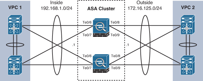
As you add more members to the cluster, their interfaces seamlessly bundle into the data EtherChannels and respond to the cluster virtual IP and MAC addresses as well. Adjacent switches use regular EtherChannel hashing to load-balance the existing traffic across more member ports. Similarly, traffic handled by members of the cluster that have been removed seamlessly rebalances across the remaining units. The transparent addition and removal of cluster members along with the first-hop redundancy capabilities make Spanned EtherChannel the preferred choice for clustering deployments.
Prior to ASA 9.2(1) software, cluster-spanned EtherChannels required all member ports to connect to a single physical switch or a logical VSS or vPC switch pair. ASA 9.2(1) software enables long distance clustering deployments where member interfaces of a single cluster-spanned EtherChannel may connect to different logical switches. In such scenarios, avoid forwarding loops by preventing direct Layer 2 adjacency between different parts of this split data EtherChannel on the switch side.
When you configure a Spanned EtherChannel cluster to participate in dynamic routing, only the master unit establishes routing adjacencies. All slave units synchronize the routing table from the master. Similarly to failover, a new master unit must reestablish the adjacencies when the original master fails or relinquishes the role through manual configuration. Normal traffic forwarding through the cluster continues using the cached routing table until the adjacencies reestablish.
Individual Mode
Data interfaces in Individual mode require a pool of IP addresses in addition to the virtual cluster IP address. This pool should contain enough addresses for the maximum expected number of cluster members. The cluster master always responds to the virtual IP address for management connections. All units receive IP addresses from the configured pool for actual data forwarding, so the master unit always has two IP addresses assigned to each data interface in this mode. You can similarly define MAC address pool, but each unit will use its own burned-in addresses by default. Because each ASA processes traffic individually in this mode, you do not have to configure virtual MAC addresses on all data interfaces.
Figure 16-16 illustrates a two-unit cluster in Individual interface mode. TenGigabitEthernet0/6 and 0/7 interfaces of the master unit are bundled into a local EtherChannel. Because all units in the cluster share the same configuration, the slave unit bundles the same interfaces into a local EtherChannel as well. Both of these EtherChannel links connect to the inside network. The master unit owns the virtual IP address of 192.168.1.1 and the assigned unit IP address of 192.168.1.2 on the inside; the slave responds on the assigned unit IP address of 192.168.1.3 on this interface. The virtual IP address of 192.168.1.1 follows the master unit, and the other IP addresses are assigned to the units from the common pool by the master. Adjacent inside endpoints treat the two cluster members as separate next-hop devices even though they share the same configuration. The outside segment has a similar configuration with 172.16.125.1, 172.16.125.2, and 172.16.125.3 IP addresses, respectively. Example 16-16 shows the corresponding configuration of the outside EtherChannel interface.

Example 16-16 ASA EtherChannel Configuration in Individual Mode
ip local pool OUTSIDE 172.16.125.2-172.16.125.3
!
interface Port-channel1
nameif outside
security-level 0
ip address 172.16.125.1 255.255.255.0 cluster-pool OUTSIDE
In Figure 16-16, the inside ASA interfaces connect to two separate physical switches. In this configuration, both links of each inside EtherChannel must connect to the same switch. Because the outside ASA interfaces connect to a vPC switch pair, each local EtherChannel connects to both physical switches in the logical pair for additional redundancy.
You have two options for load-balancing traffic to an individual interface mode cluster from external devices:
![]() Policy Based Routing (PBR): Use static route maps to distribute connections between different cluster members based on IP and transport port information. Use access control lists (ACL) to split the traffic load based on IP and transport port information. The downstream router sets next-hop information for each packet based on the configured pool of IP addresses on each cluster data interface. Object tracking and SLA monitor features detect individual cluster member failures and dynamically remove them from the PBR pool. The biggest downside of PBR is the static nature of traffic distribution, because you cannot dynamically load-balance flows based on actual load.
Policy Based Routing (PBR): Use static route maps to distribute connections between different cluster members based on IP and transport port information. Use access control lists (ACL) to split the traffic load based on IP and transport port information. The downstream router sets next-hop information for each packet based on the configured pool of IP addresses on each cluster data interface. Object tracking and SLA monitor features detect individual cluster member failures and dynamically remove them from the PBR pool. The biggest downside of PBR is the static nature of traffic distribution, because you cannot dynamically load-balance flows based on actual load.
![]() Equal-Cost Multipath (ECMP): Use static or dynamic routing to load-balance traffic between multiple cluster members based on IP and transport port hashing. The downstream router typically performs per-flow load balancing, so all packets for the same connection arrive to the same cluster member. Object tracking and the SLA monitor feature detect cluster unit failures with static routing. Dynamic routing protocols allow faster convergence on cluster member failures. Use this approach instead of PBR to dynamically load-balance incoming connections between available cluster members.
Equal-Cost Multipath (ECMP): Use static or dynamic routing to load-balance traffic between multiple cluster members based on IP and transport port hashing. The downstream router typically performs per-flow load balancing, so all packets for the same connection arrive to the same cluster member. Object tracking and the SLA monitor feature detect cluster unit failures with static routing. Dynamic routing protocols allow faster convergence on cluster member failures. Use this approach instead of PBR to dynamically load-balance incoming connections between available cluster members.
The overall complexities of traffic load balancing as well as the inability to provide first-hop redundancy to the directly connected endpoints make Individual interface mode the least preferred choice for clustering deployments.
Each individual mode cluster member establishes independent dynamic routing protocol adjacencies. Units never peer with each other on the same network segment. Because all of the ASAs should connect to the same networks on all data interfaces, the routing tables should, theoretically, match across the cluster. Certain unusual network designs may take advantage of this flexibility and connect different units to different networks on the same data interface. Keep in mind that each unit has the same configuration on all matching data interfaces, including the IP subnet. Such discontiguous designs are supported for long distance clustering deployments in ASA 9.1(4) and later software.
Cluster Management
Use any regular data interface for connecting to the cluster for management purposes. Because all configuration changes must happen on the master unit, always connect to the virtual cluster IP address in either Spanned EtherChannel mode or Individual mode. Consider using an out-of-band management network to ensure access to the cluster even if network connectivity to the data interfaces is lost.
You have the option of enabling a dedicated management interface with the management-only keyword. Such an interface allows individual IP address configuration with an address pool even when the cluster is operating in Spanned EtherChannel mode. This gives you the ability to access each cluster member individually for monitoring or troubleshooting purposes; SNMP polling is one of such use cases. The dedicated management interface in Spanned EtherChannel mode does not have the ability to participate in dynamic routing; you must configure appropriate static routes instead.
Each cluster member uses its own assigned interface IP addresses for outbound management connections. In Spanned EtherChannel mode, all units independently generate syslog and NetFlow messages from the same virtual IP address on the closest interface based on the routing table. Use the logging device-id command to differentiate syslog messages received from different cluster members.
Cluster Health Monitoring
Each cluster member constantly monitors the state of its cluster control link interface. If the cluster control link goes down, the member automatically shuts down all data interfaces and disables clustering. You must manually re-enable clustering after this type of a failure even if the cluster control link of the failed member comes back up.
By default, all units broadcast keepalive messages on the cluster control link every second. This interval is always set to one-third of the configured health check hold time, and the default hold time value is 3 seconds. If you set the hold time to the lowest possible value of 800 ms, each unit generates keepalive messages every 266 ms. This hold time effectively determines how soon the cluster can detect a unit failure. A lower hold time value enables quicker cluster reconvergence on member failure, but it may also cause an operational cluster member to erroneously drop out under high load.
Cluster members rely on these keepalive messages for the following purposes:
![]() Unit health monitoring: The master removes a slave unit from the cluster after missing its three successive keepalives. If slave units stop receiving keepalive messages from the master, they elect a new master and remove the unresponsive master unit from the cluster.
Unit health monitoring: The master removes a slave unit from the cluster after missing its three successive keepalives. If slave units stop receiving keepalive messages from the master, they elect a new master and remove the unresponsive master unit from the cluster.
![]() Interface monitoring: Each unit monitors the state of its data interfaces and compares this information to all other cluster members. Interface tests include a simple check of the interface link state in all interface modes and cLACP bundling status in Spanned EtherChannel mode. When using a hardware or software IPS feature module on ASA 5500-X and ASA 5585-X appliances, each cluster member monitors and compares the module status as well. If a unit detects an interface or module failure while at least one other cluster member reports the same interface or module in a good state, the failed ASA shuts down all of its data interfaces and disables clustering. This unit attempts to automatically re-enable clustering after 5 minutes. If the problem with the failed data interface or module persists, another rejoin occurs after 10 minutes. The last re-join attempt occurs after another 20 minutes. You need to manually re-enable clustering after three unsuccessful automatic attempts.
Interface monitoring: Each unit monitors the state of its data interfaces and compares this information to all other cluster members. Interface tests include a simple check of the interface link state in all interface modes and cLACP bundling status in Spanned EtherChannel mode. When using a hardware or software IPS feature module on ASA 5500-X and ASA 5585-X appliances, each cluster member monitors and compares the module status as well. If a unit detects an interface or module failure while at least one other cluster member reports the same interface or module in a good state, the failed ASA shuts down all of its data interfaces and disables clustering. This unit attempts to automatically re-enable clustering after 5 minutes. If the problem with the failed data interface or module persists, another rejoin occurs after 10 minutes. The last re-join attempt occurs after another 20 minutes. You need to manually re-enable clustering after three unsuccessful automatic attempts.
Disable these keepalive messages with the no health-check clustering configuration mode command only in the following cases:
![]() When adding or removing cluster members
When adding or removing cluster members
![]() When making changes to data interfaces
When making changes to data interfaces
![]() When adding or removing IPS SSP on ASA 5585-X appliances
When adding or removing IPS SSP on ASA 5585-X appliances
This step minimizes the possibility of false failure detection events and associated traffic disruptions. Make sure to always re-enable the cluster health checks after completing the changes.
Network Address Translation
Clustering supports all forms of Network Address Translation (NAT) and Port Address Translation (PAT):
![]() Static NAT and PAT: Each unit translates and untranslates packets based on the local configuration. Because static translations do not change during operation, cluster members do not need to exchange or maintain any additional data for these types of connections.
Static NAT and PAT: Each unit translates and untranslates packets based on the local configuration. Because static translations do not change during operation, cluster members do not need to exchange or maintain any additional data for these types of connections.
![]() Dynamic NAT: The cluster master must create these translations based on requests from other units. A flow owner sends the request to the master at the time of connection creation. The master propagates the translation information to all units in the cluster. This way, forwarder units can untranslate response packets without having to query the master.
Dynamic NAT: The cluster master must create these translations based on requests from other units. A flow owner sends the request to the master at the time of connection creation. The master propagates the translation information to all units in the cluster. This way, forwarder units can untranslate response packets without having to query the master.
![]() Dynamic PAT: The cluster master distributes IP addresses from the configured dynamic PAT pools evenly to all members. Each flow owner creates translations from its local pool and becomes the translation owner as well. Another unit holds a backup translation entry to protect against an original owner failure. Each member allocates PAT entries for new connections until it runs out of available ports and addresses; any subsequent connection fails. Always configure a sufficient number of PAT IP addresses for all cluster members. The master always maintains an even PAT pool allocation without considering the actual load of each individual unit. Additional notes on dynamic per-session and multisession translation behavior are provided after this list.
Dynamic PAT: The cluster master distributes IP addresses from the configured dynamic PAT pools evenly to all members. Each flow owner creates translations from its local pool and becomes the translation owner as well. Another unit holds a backup translation entry to protect against an original owner failure. Each member allocates PAT entries for new connections until it runs out of available ports and addresses; any subsequent connection fails. Always configure a sufficient number of PAT IP addresses for all cluster members. The master always maintains an even PAT pool allocation without considering the actual load of each individual unit. Additional notes on dynamic per-session and multisession translation behavior are provided after this list.
![]() Interface PAT: Only available in Spanned EtherChannel mode. Because the master unit controls the cluster virtual IP addresses in this mode, all connections that use interface PAT become centralized. Avoid using interface PAT for best performance and scalability.
Interface PAT: Only available in Spanned EtherChannel mode. Because the master unit controls the cluster virtual IP addresses in this mode, all connections that use interface PAT become centralized. Avoid using interface PAT for best performance and scalability.
By default, all dynamic PAT entries use the new per-session model in ASA 9.0(1) and later software for the following types of connections:
![]() IPv4 and IPv6 TCP
IPv4 and IPv6 TCP
![]() IPv4 and IPv6 UDP-based DNS (port 53)
IPv4 and IPv6 UDP-based DNS (port 53)
In this model, the translation entry terminates immediately when the underlying connection closes. This behavior suits most protocols, such as HTTP or HTTPS. Dynamic PAT entries for other connections use the legacy multisession model where the translation remains active for some time after all the underlying connections close. You can change this idle timeout from the default value of 30 seconds with the global timeout pat-xlate command. The multisession translation behavior is necessary for some applications that use the same socket for multiple bidirectional connections. Examples of such connections include peer-to-peer and Voice over IP (VoIP) sessions.
Example 16-17 shows the default per-session translation configuration. You can exclude connections from that list with the xlate per-session deny command and add other types of connection with the xlate per-session permit statements.
Example 16-17 Default Per-Session PAT Translation Configuration
xlate per-session permit tcp any4 any4
xlate per-session permit tcp any4 any6
xlate per-session permit tcp any6 any4
xlate per-session permit tcp any6 any6
xlate per-session permit udp any4 any4 eq domain
xlate per-session permit udp any4 any6 eq domain
xlate per-session permit udp any6 any4 eq domain
xlate per-session permit udp any6 any6 eq domain
Only per-session dynamic PAT connections can take advantage of the distributed cluster processing. The master unit must process all connections that utilize multisession dynamic PAT, so such flows become centralized. If most of your applications require multi-session dynamic translations, the cluster master may exhaust its allocation of the dynamic PAT pools before other units. Increase the overall dynamic PAT pool size accordingly.
Performance
Clustering delivers best throughput when handling little to no asymmetrically routed traffic. External load-balancing mechanisms should strive to deliver all packets for the same flow directly to the owner rather than rely on flow forwarders. For this to happen, follow these guidelines:
![]() Use Spanned EtherChannel mode: Predictable EtherChannel hashing algorithms maintain flow symmetry at the adjacent switches. Using a single VLAN trunk connection for all data interfaces inherently assures this symmetry. If you connect multiple cluster-spanned data EtherChannels to different switches, ensure that the EtherChannel load-balancing algorithms match between all of them. Using PBR and ECMP in Individual interface mode may also provide flow symmetry, but the required configuration is typically more complex.
Use Spanned EtherChannel mode: Predictable EtherChannel hashing algorithms maintain flow symmetry at the adjacent switches. Using a single VLAN trunk connection for all data interfaces inherently assures this symmetry. If you connect multiple cluster-spanned data EtherChannels to different switches, ensure that the EtherChannel load-balancing algorithms match between all of them. Using PBR and ECMP in Individual interface mode may also provide flow symmetry, but the required configuration is typically more complex.
![]() Avoid NAT: NAT and PAT always cause asymmetry between different directions of the same flow, because the IP and transport port information hashes to different values between the real and mapped packet headers. NAT significantly reduces the overall forwarding performance of the cluster because of the flow asymmetry and the additional processing overhead of dynamic translations.
Avoid NAT: NAT and PAT always cause asymmetry between different directions of the same flow, because the IP and transport port information hashes to different values between the real and mapped packet headers. NAT significantly reduces the overall forwarding performance of the cluster because of the flow asymmetry and the additional processing overhead of dynamic translations.
![]() Minimize centralized features: The main advantage of clustering is in distributing the traffic processing load among multiple physical units. Certain features require processing by the master unit, so all associated connections must go through the single ASA. The performance of a cluster reduces to that of a single appliance if the majority of transit connections are centralized.
Minimize centralized features: The main advantage of clustering is in distributing the traffic processing load among multiple physical units. Certain features require processing by the master unit, so all associated connections must go through the single ASA. The performance of a cluster reduces to that of a single appliance if the majority of transit connections are centralized.
Centralized Features
The master unit processes all incoming packets and generates all outgoing packets that pertain to the following centralized functions:
![]() PIM and IGMP in routed mode
PIM and IGMP in routed mode
![]() RIP, EIGRP, and OSPF in Spanned EtherChannel mode
RIP, EIGRP, and OSPF in Spanned EtherChannel mode
![]() Site-to-site IPsec tunnel negotiation and termination
Site-to-site IPsec tunnel negotiation and termination
![]() AAA server connections for cut-through proxy
AAA server connections for cut-through proxy
Slave units redirect all connections that belong to the following centralized features to the master unit:
![]() Advanced application inspection: This includes any traffic matching DCERPC, ESMTP, IM, NetBIOS, PPTP, RADIUS, RSH, SNMP, SQL*Net, Sun RPC, TFTP, and XDMCP inspection engines (all but RADIUS were covered in Chapter 13). The FTP inspection engine is only centralized when the underlying connections match cut-through proxy. URL filtering is centralized as well.
Advanced application inspection: This includes any traffic matching DCERPC, ESMTP, IM, NetBIOS, PPTP, RADIUS, RSH, SNMP, SQL*Net, Sun RPC, TFTP, and XDMCP inspection engines (all but RADIUS were covered in Chapter 13). The FTP inspection engine is only centralized when the underlying connections match cut-through proxy. URL filtering is centralized as well.
![]() Site-to-site VPN: This includes any transit or to-the-box connections that traverse a VPN tunnel.
Site-to-site VPN: This includes any transit or to-the-box connections that traverse a VPN tunnel.
![]() Multicast packets: This applies only to multicast data flows in Individual interface mode. These data connections remain distributed in the Spanned EtherChannel mode.
Multicast packets: This applies only to multicast data flows in Individual interface mode. These data connections remain distributed in the Spanned EtherChannel mode.
When configured with an IPS policy, each cluster member redirects traffic to the local module independently. Similarly to failover, IPS modules in different cluster members do not share the configuration or stateful connection tables.
Scaling Factors
In an average case, expect the combined forwarding capacities of the cluster members to scale as follows:
![]() Throughput at 70 percent: The total throughput of a cluster reaches about 70 percent of the combined maximum throughput of all members. For instance, an ASA 5585-X appliance with an SSP-60 module can pass about 20 Gbps of multiprotocol traffic. If you combine two such firewalls into a cluster, the combined multiprotocol throughput reaches 28 Gbps on average. If you extend this cluster to 16 members, this figure increases to 224 Gbps. This scaling factor can go as high as 100 percent with perfectly symmetric traffic and drop significantly lower when all connections use NAT.
Throughput at 70 percent: The total throughput of a cluster reaches about 70 percent of the combined maximum throughput of all members. For instance, an ASA 5585-X appliance with an SSP-60 module can pass about 20 Gbps of multiprotocol traffic. If you combine two such firewalls into a cluster, the combined multiprotocol throughput reaches 28 Gbps on average. If you extend this cluster to 16 members, this figure increases to 224 Gbps. This scaling factor can go as high as 100 percent with perfectly symmetric traffic and drop significantly lower when all connections use NAT.
![]() Maximum connection entries at 60 percent: Because cluster members maintain additional stub connection entries, the true maximum connection size of each unit reduces by about 40 percent. If you have an ASA 5585-X with an SSP-60 that can handle up to 10 million stateful connections on its own, each such cluster member is able to maintain about 6 million such connections. You can scale up to 96 million connections with a cluster of 16 such appliances.
Maximum connection entries at 60 percent: Because cluster members maintain additional stub connection entries, the true maximum connection size of each unit reduces by about 40 percent. If you have an ASA 5585-X with an SSP-60 that can handle up to 10 million stateful connections on its own, each such cluster member is able to maintain about 6 million such connections. You can scale up to 96 million connections with a cluster of 16 such appliances.
![]() Maximum connection creation rate at 50 percent: Due to the additional tasks associated with the flow creation process, each cluster member can create fewer connections per second than in standalone mode. An ASA 5585-X with SSP-60 creates about 350,000 connections per second on its own. In a cluster, it creates about 175,000 connections per second. With 16 such appliances in a cluster, the overall maximum connection creation rate can reach 2.8 million flows per second.
Maximum connection creation rate at 50 percent: Due to the additional tasks associated with the flow creation process, each cluster member can create fewer connections per second than in standalone mode. An ASA 5585-X with SSP-60 creates about 350,000 connections per second on its own. In a cluster, it creates about 175,000 connections per second. With 16 such appliances in a cluster, the overall maximum connection creation rate can reach 2.8 million flows per second.
Packet Flow
Depending on the type of connection and external load balancing, there are several main categories of packet flow through a cluster:
![]() TCP connections: All packets for fully stateful TCP connections always traverse the flow owner. By default, the owner encodes its identity into the initial TCP SYN segment using a sequence number cookie mechanism. If the response arrives to a different unit, any flow forwarder can determine the identity of the owner from the TCP SYN ACK packet without querying the flow director. You must keep the TCP sequence number randomization feature enabled for this mechanism to work.
TCP connections: All packets for fully stateful TCP connections always traverse the flow owner. By default, the owner encodes its identity into the initial TCP SYN segment using a sequence number cookie mechanism. If the response arrives to a different unit, any flow forwarder can determine the identity of the owner from the TCP SYN ACK packet without querying the flow director. You must keep the TCP sequence number randomization feature enabled for this mechanism to work.
![]() UDP and other pseudo-stateful connections: Similarly to TCP, the flow owner must process all packets for such a connection. Because the sequence number cookie mechanism is not available with non-TCP connections, the flow owner and forwarders must always query the director after receiving the first packet for such a flow.
UDP and other pseudo-stateful connections: Similarly to TCP, the flow owner must process all packets for such a connection. Because the sequence number cookie mechanism is not available with non-TCP connections, the flow owner and forwarders must always query the director after receiving the first packet for such a flow.
![]() Centralized connections: The master unit must process all packets for any centralized features. All other units can only act as forwarders for such flows.
Centralized connections: The master unit must process all packets for any centralized features. All other units can only act as forwarders for such flows.
![]() Unidirectional connections: Connections such as GRE do not require bidirectional state tracking. Different units may own such connections and forward the packets locally.
Unidirectional connections: Connections such as GRE do not require bidirectional state tracking. Different units may own such connections and forward the packets locally.
TCP Connection Processing
Figure 16-17 illustrates a packet flow through the cluster for a TCP connection.
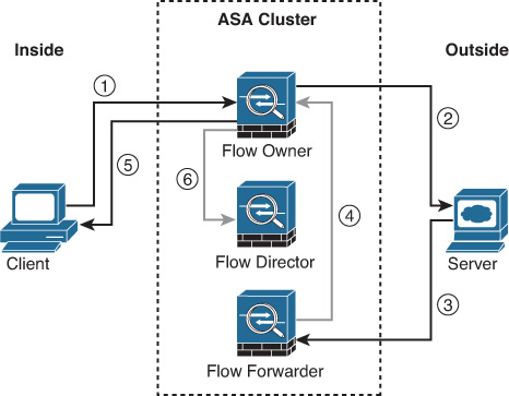
The following events occur in Figure 16-17:
1. An inside client sends a TCP SYN packet to the outside server through the ASA cluster. One member receives this packet.
2. Because this is the first packet in a new TCP connection, the receiving unit becomes the flow owner. It evaluates the configured security policy and creates the new connection. The owner encodes its information into the TCP SYN packet using a sequence number cookie and transmits it to the server.
3. The server replies with a TCP SYN ACK packet to the client through the ASA cluster. In an ideal situation, this response would arrive symmetrically to the flow owner. Due to differences in load-balancing mechanisms between the inside and outside interfaces or NAT, this packet arrives to a different cluster member instead.
4. The receiving cluster member decodes the owner information from the sequence number cookie in the TCP SYN ACK packet and becomes the flow forwarder. It redirects the packet to the flow owner through the cluster control link.
5. The flow owner processes the packet and forwards it back to the client.
6. The flow owner sends a stateful update to the flow director. It calculates the flow director identity based on the source and destination IP and TCP port numbers for the connection. The flow director creates a stub connection entry and stores the identity of the flow owner.
UDP Connection Processing
Figure 16-18 illustrates a packet flow through the cluster for a UDP connection.
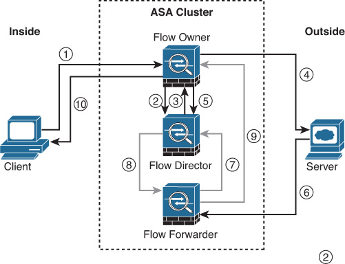
The following events occur in Figure 16-18:
1. An inside client sends a UDP packet for a new connection to the server thorough the ASA cluster. One member receives this packet.
2. Unlike TCP, UDP does not indicate whether the packet pertains to an existing or new connection. The receiving unit identifies the flow director from the source and destination IP and UDP port information and sends a flow owner query over the cluster control link.
3. The flow director has no existing flow entry, so it instructs the receiving unit to assume ownership of this flow.
4. The new flow owner creates the connections based on the configured policy and forwards the packet to the server.
5. The flow owner updates the connection state to the flow director.
6. The server replies to the client. Due to traffic asymmetry, the response arrives to a different cluster member.
7. The receiving cluster member computes the director identity from the packet information and sends a flow owner query over the cluster control link.
8. The flow director responds with the identity of the flow owner.
9. The receiving unit becomes the flow forwarder and redirects the response packet to the identified flow owner using the cluster control link.
10. The original owner processes the response and forwards it to the client.
Centralized Connection Processing
Figure 16-19 illustrates a packet flow through the cluster for a centralized connection.

The following events occur in Figure 16-19:
1. An inside host sends a packet to an outside host through the ASA cluster. It could also be a management packet destined to the cluster itself. One member receives this packet.
2. Based on the local configuration, the receiving unit determines that the packet pertains to a centralized feature. The cluster master must process all such connections, so the receiving unit becomes the flow forwarder and redirects the packet over the cluster control link.
3. The master unit processes this packet and forwards it to the destination.
4. For non-management connections, the cluster master identifies the corresponding flow director and sends a stateful flow update.
Using the cluster master command to change the current master unit clears all centralized connections. Disable clustering on the existing master or reload it to gracefully transfer most centralized connections to a different unit.
State Transition
When you configure an ASA for clustering or when an existing cluster member boots up, the device goes through the following steps before enabling its data interfaces:
1. Transition to the Election state and attempt to discover an existing master on the cluster control link for about 45 seconds. Similarly to failover, this delay prevents the unit from becoming the master while STP is converging on its cluster control interface. Disable STP or enable STP PortFast on all switch ports in the cluster control link segment to speed up the master detection process.
2. If an existing master responds, proceed to the Slave Cold state and request the cluster configuration from the master. The master can only admit one cluster member at a time, so the current unit may transition to the On Call state until the master is ready to continue. After that, the configuration synchronization happens in the Slave Config state. Other operational cluster information synchronizes during the Slave Bulk Sync phase. After receiving all of the necessary information and programming the appropriate IP and MAC addresses based on the current configuration, the unit enables its data interfaces and proceeds to normal transit traffic forwarding in the Slave state. The unit may also transition to the Disabled state if any problem occurs during this negotiation process.
3. If the master does not exist, all available cluster units remain in the Election phase to select the master. The unit with the numerically lowest configured cluster priority wins the election. If the priority is the same between two or more units, unit name and serial number values break the tie. The winner transitions to the Master state. The elected master holds this role until it fails or reloads. You can also use the cluster master command to promote another member into the master role, but this option is not recommended because of its negative effect on centralized connections.
A failed cluster member always disables clustering and transitions to the Disabled state. Refer to the “Cluster Health Monitoring” section for additional information on when a failed member automatically attempts to rejoin the cluster.
Configuring Clustering
Begin clustering configuration on a single unit that will become the master. Then add slave units to the cluster one by one. Because many configuration elements change with clustering, use the clear configure all command on any ASAs with preexisting configuration. Make sure to set the correct boot variable after clearing the configuration in case you have multiple ASA images stored in the flash. Upon clearing the configuration, you must use the serial console to complete the cluster interface mode selection. If desired, enable the transparent firewall mode after this step with the firewall transparent command when deploying the cluster in single-context mode. Then configure basic management settings and continue the deployment process with ASDM. You cannot use SSH or Telnet to enable clustering. When desired, you should switch to multiple-context mode before starting the rest of the configuration process.
The following prerequisites apply to the clustering configuration process:
![]() Designate a dedicated management interface. Ideally, you should use the same interface to configure the cluster through ASDM.
Designate a dedicated management interface. Ideally, you should use the same interface to configure the cluster through ASDM.
![]() When using ASA 5580 and ASA 5585-X appliances, make sure that all cluster members have the correct Cluster licenses. With ASA 5512-X appliances, ensure that all units have the Security Plus license. 10GE I/O and Encryption-3DES-AES licenses must be either enabled or disabled on all units.
When using ASA 5580 and ASA 5585-X appliances, make sure that all cluster members have the correct Cluster licenses. With ASA 5512-X appliances, ensure that all units have the Security Plus license. 10GE I/O and Encryption-3DES-AES licenses must be either enabled or disabled on all units.
![]() Pick one or more separate physical interfaces for the cluster control link. Make sure that these physical interfaces are enabled with the no shutdown command or by checking the Enable Interface check box in the Edit dialog box on the Configuration > Device Setup > Interfaces panel in ASDM. When possible, you should bundle several physical interfaces into a cluster control link EtherChannel. When using a VSS or vPC logical switch, the individual ports of this EtherChannel on each cluster member should connect to both of the physical switches for best reliability. Cluster control link EtherChannels cannot span multiple cluster units or connect to two different standalone switches from a single ASA.
Pick one or more separate physical interfaces for the cluster control link. Make sure that these physical interfaces are enabled with the no shutdown command or by checking the Enable Interface check box in the Edit dialog box on the Configuration > Device Setup > Interfaces panel in ASDM. When possible, you should bundle several physical interfaces into a cluster control link EtherChannel. When using a VSS or vPC logical switch, the individual ports of this EtherChannel on each cluster member should connect to both of the physical switches for best reliability. Cluster control link EtherChannels cannot span multiple cluster units or connect to two different standalone switches from a single ASA.
![]() Identify an isolated IP subnet for the cluster control link. This subnet must accommodate at least the maximum expected number of cluster members. It cannot overlap with any data interfaces. When possible, use a separate switch or a VDC for the cluster control link VLAN. Disable STP on that VLAN or configure all the ports with STP PortFast.
Identify an isolated IP subnet for the cluster control link. This subnet must accommodate at least the maximum expected number of cluster members. It cannot overlap with any data interfaces. When possible, use a separate switch or a VDC for the cluster control link VLAN. Disable STP on that VLAN or configure all the ports with STP PortFast.
![]() Enable jumbo frames with the jumbo-frame reservation command and reload each unit.
Enable jumbo frames with the jumbo-frame reservation command and reload each unit.
![]() Choose between Spanned EtherChannel mode and Individual interface mode. The difference in the interface configuration format makes any subsequent changes between these modes very complex and time consuming.
Choose between Spanned EtherChannel mode and Individual interface mode. The difference in the interface configuration format makes any subsequent changes between these modes very complex and time consuming.
![]() Identify virtual IP addresses for all data interfaces. Designate an IP address pool for the dedicated management interface. When using Individual interface mode, specify an IP address pool for each data interface. Each of these pools must have enough addresses to accommodate the maximum expected number of cluster members.
Identify virtual IP addresses for all data interfaces. Designate an IP address pool for the dedicated management interface. When using Individual interface mode, specify an IP address pool for each data interface. Each of these pools must have enough addresses to accommodate the maximum expected number of cluster members.
![]() In Spanned EtherChannel mode, identify virtual MAC addresses for each data EtherChannel link. You can also configure virtual MAC addresses for all logical data interfaces. In Individual mode, create MAC address pools for each data interface similarly to the IP address pools.
In Spanned EtherChannel mode, identify virtual MAC addresses for each data EtherChannel link. You can also configure virtual MAC addresses for all logical data interfaces. In Individual mode, create MAC address pools for each data interface similarly to the IP address pools.
Setting Interface Mode
You must use the command line on each prospective cluster member to select the cluster interface mode. If you intend to use ASDM to configure the slave units, you only need to set the interface mode on the master. Always perform this step through the serial console connection. When using multiple-context mode, you must perform this operation in the system context. There are three options for completing this task:
![]() Issue the cluster interface-mode {spanned | individual} command and follow the prompts. If the current configuration does not contain any incompatible elements, the mode changes right away. Otherwise, the ASA presents a confirmation prompt for clearing the current configuration and performing a reload. Example 16-18 shows such a prompt when attempting to enable Individual interface mode. Proceed with the suggestion to avoid problems in the subsequent steps.
Issue the cluster interface-mode {spanned | individual} command and follow the prompts. If the current configuration does not contain any incompatible elements, the mode changes right away. Otherwise, the ASA presents a confirmation prompt for clearing the current configuration and performing a reload. Example 16-18 shows such a prompt when attempting to enable Individual interface mode. Proceed with the suggestion to avoid problems in the subsequent steps.
Example 16-18 Cluster Interface Mode Selection
asa(config)# cluster interface-mode individual
WARNING: Current running configuration contains commands that are incompatible
with 'individual' mode.
- You can choose to proceed, device configuration will be cleared, and a reboot
will be initiated.
- You can use 'cluster interface-mode individual check-details' command to list
all of the running configuration elements that are incompatible with 'individual'
mode, remove these commands manually, and attempt the interface-mode change
again.
- Or you can use command 'cluster interface-mode individual force' to force the
interface-mode change without validating compatibility of the running
configuration. Once the interface-mode is changed, you still need to resolve any
remaining configuration conflicts in order to be able to enable clustering.
WARNING: Do you want to proceed with changing the interface-mode, clear the
device configuration, and initiate a reboot?
[confirm]
![]() Issue the cluster interface-mode {spanned | individual} check-details command to review the specific set of incompatible commands and remove or change them manually. Then issue the cluster interface-mode {spanned | individual} command to set the interface mode.
Issue the cluster interface-mode {spanned | individual} check-details command to review the specific set of incompatible commands and remove or change them manually. Then issue the cluster interface-mode {spanned | individual} command to set the interface mode.
![]() Issue the cluster interface-mode {spanned | individual} force command to set the interface mode without validating the configuration. This is only appropriate on slave units, which synchronize the full configuration from the master anyway. Never use this option when configuring the master unit.
Issue the cluster interface-mode {spanned | individual} force command to set the interface mode without validating the configuration. This is only appropriate on slave units, which synchronize the full configuration from the master anyway. Never use this option when configuring the master unit.
ASA stores the cluster interface mode setting in a reserved region of the system flash, so it will not appear in the running or startup configuration files. You must use the show cluster interface-mode command to determine the current setting.
Management Access for ASDM Deployment
The ASDM High Availability and Scalability Wizard automates and significantly simplifies the clustering deployment process. You only need to select the interface mode on the master unit if you intend to use this wizard. ASDM connects to the slave units and provisions the desired settings automatically. First, you must provision basic management connectivity and enable ASDM access by following these steps:
1. Because the master unit already has the cluster interface mode set, create an IP address pool for the dedicated management interface with the ip local pool command. Use the same pool for the designated management interface after your cluster is up and running. Recall that each unit uses a separate IP address on this management interface even when operating in the Spanned EtherChannel mode. The rest of the basic management configuration remains the same. Example 16-19 shows such a configuration on the master unit. The master uses the virtual cluster IP as well as the first address from this pool.
Example 16-19 Basic Management Configuration on Master Unit
ip local pool CLUSTER_MANAGEMENT 172.16.162.243-172.16.162.250
!
interface Management0/0
description management interface
management-only
nameif mgmt
security-level 0
ip address 172.16.162.242 255.255.255.224 cluster-pool CLUSTER_MANAGEMENT
!
route mgmt 0.0.0.0 0.0.0.0 172.16.162.225 1
!
http server enable
http 0.0.0.0 0.0.0.0 mgmt
!
aaa authentication http console LOCAL
username cisco password cisco privilege 15
2. Configure dedicated management interfaces on the slave units normally. Use IP addresses from the same designated management interface pool. You do not need to install an ASDM image on each slave unit in this step. Example 16-20 shows a typical configuration that allows ASDM access on a slave unit.
Example 16-20 Basic Management Configuration on Slave Unit
interface Management0/0
description management interface
management-only
nameif mgmt
security-level 0
ip address 172.16.162.244 255.255.255.224
!
route mgmt 0.0.0.0 0.0.0.0 172.16.162.225 1
!
http server enable
http 0.0.0.0 0.0.0.0 mgmt
!
aaa authentication http console LOCAL
username cisco password cisco privilege 15
Make sure that you can connect to each prospective cluster member with ASDM before proceeding with the configuration process.
Building a Cluster
Connect to the master unit with ASA and launch the High Availability and Scalability Wizard from the Wizards menu. Proceed with the following steps:
1. The Configuration Type screen allows you to select between failover and clustering deployments. Because you already configured the interface mode, ASA Cluster becomes the only available option. After reviewing the basic hardware and software ASA information and the selected interface mode, click Next to proceed.
2. The ASA Cluster Options screen offers you options to either configure a new cluster or add this unit to an existing cluster. Because you are configuring the master unit, choose the first option, Set Up a New ASA Cluster, and click Next to continue.
3. The ASA Cluster Mode screen confirms the current interface mode selection and displays some information about Spanned EtherChannel and Individual modes. You cannot change the interface mode through ASDM. After reviewing the information, click Next to proceed with the configuration process.
4. The Interfaces screen allows you to change some basic physical interface settings. You can also click the Add EtherChannel Interface for Cluster Control Link button if you have not configured the cluster control link interfaces previously. Click Next to continue.
5. Use the ASA Cluster Configuration screen to configure basic cluster settings. Figure 16-20 shows sample values.
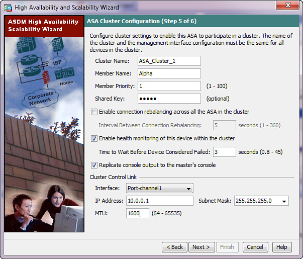
Set the following parameters and then click Next when you are finished:
![]() Cluster Name: Assign a name to the cluster. This string cannot contain spaces or special characters. In the example shown in Figure 16-20, ASA_Cluster_1 is used as the name.
Cluster Name: Assign a name to the cluster. This string cannot contain spaces or special characters. In the example shown in Figure 16-20, ASA_Cluster_1 is used as the name.
![]() Member Name: You must assign each cluster member a unique name. This string cannot contain spaces or special characters. Alpha is employed as the name of this first unit in this example.
Member Name: You must assign each cluster member a unique name. This string cannot contain spaces or special characters. Alpha is employed as the name of this first unit in this example.
![]() Member Priority: The priority value decides which unit becomes the cluster master during the election process. A lower numerical value implies higher priority. Always configure the first unit with a lower priority value. Figure 16-20 assigns this unit the highest priority for the master election.
Member Priority: The priority value decides which unit becomes the cluster master during the election process. A lower numerical value implies higher priority. Always configure the first unit with a lower priority value. Figure 16-20 assigns this unit the highest priority for the master election.
![]() Shared Key: Cluster members use this optional string to encrypt configuration and control messages on the cluster control link.
Shared Key: Cluster members use this optional string to encrypt configuration and control messages on the cluster control link.
![]() Enable Connection Rebalancing Across All the ASA in the Cluster: Check this box if you want all cluster members to compare the incoming connection rates. If a particular member receives more new connections than its peers over the specified Interval Between Connection Rebalancing period, the unit offloads some of the new connections to other members during the next monitoring period. Use this option with caution, because it may increase processing load on an already overloaded unit and cause excessive packet redirection on the cluster control link. In this case, this option is disabled.
Enable Connection Rebalancing Across All the ASA in the Cluster: Check this box if you want all cluster members to compare the incoming connection rates. If a particular member receives more new connections than its peers over the specified Interval Between Connection Rebalancing period, the unit offloads some of the new connections to other members during the next monitoring period. Use this option with caution, because it may increase processing load on an already overloaded unit and cause excessive packet redirection on the cluster control link. In this case, this option is disabled.
![]() Enable Health Monitoring of This Device Within the Cluster: Keep this box checked to enable cluster control link keepalives within the cluster. Adjust the Time to Wait Before Device Considered Failed setting from the default value of 3 seconds. Each unit generates the keepalive messages every one-third of the specified wait time. Refer to the “Cluster Health Monitoring” section earlier in the chapter for additional information on this feature. In this example, health monitoring is enabled with the default hold time of 3 seconds.
Enable Health Monitoring of This Device Within the Cluster: Keep this box checked to enable cluster control link keepalives within the cluster. Adjust the Time to Wait Before Device Considered Failed setting from the default value of 3 seconds. Each unit generates the keepalive messages every one-third of the specified wait time. Refer to the “Cluster Health Monitoring” section earlier in the chapter for additional information on this feature. In this example, health monitoring is enabled with the default hold time of 3 seconds.
![]() Replicate Console Output to the Master’s Console: Check this box if you want to see the output from the physical console of all slave units on the master unit console. In Figure 16-20, this functionality is enabled.
Replicate Console Output to the Master’s Console: Check this box if you want to see the output from the physical console of all slave units on the master unit console. In Figure 16-20, this functionality is enabled.
![]() Cluster Control Link: Specify the interface, local unit IP address, subnet, and IP MTU parameters for the cluster control link. All cluster members must use the same interface and subnet for this link. This instance uses previously configured Port-channel1 interface as the cluster control link. The local unit employs the IP address of 10.0.0.1 on the CCL subnet of 10.0.0.0/24. The IP MTU is set to 1600 bytes, which is 100 bytes higher than the default 1500-byte value for the data interfaces.
Cluster Control Link: Specify the interface, local unit IP address, subnet, and IP MTU parameters for the cluster control link. All cluster members must use the same interface and subnet for this link. This instance uses previously configured Port-channel1 interface as the cluster control link. The local unit employs the IP address of 10.0.0.1 on the CCL subnet of 10.0.0.0/24. The IP MTU is set to 1600 bytes, which is 100 bytes higher than the default 1500-byte value for the data interfaces.
Example 16-21 shows the complete clustering configuration on the master unit from Figure 16-20. Notice that the clacp system-mac auto command generated automatically to ensure stability of cluster-spanned EtherChannels during master unit changes.
Example 16-21 Complete Basic Cluster Configuration on Master Unit
cluster group ASA_Cluster_1
key cisco
local-unit Alpha
cluster-interface Port-channel1 ip 10.0.0.1 255.255.255.0
priority 1
console-replicate
health-check holdtime 3
clacp system-mac auto system-priority 1
6. The Summary screen confirms the intended cluster settings. Review the configuration and click Finish to push the configuration to the ASA. This operation may take some time. You may also need to retype the ASA login credentials when ASDM reconnects to the master ASA. Figure 16-21 shows a popup window that confirms a successful addition of the cluster member.

7. Click Yes and add the slave units to the cluster one by one. Figure 16-22 illustrates a sample screen for this operation. Notice that most of the fields are prepopulated based on the master unit configuration.

You need to supply the following additional information for each slave unit and then click Next to complete the configuration:
![]() Member Name: Assign a unique name to the member. Figure 16-22 uses Bravo.
Member Name: Assign a unique name to the member. Figure 16-22 uses Bravo.
![]() Member Priority: Configure slave units with a lower priority for the master election. Figure 16-22 uses the highest possible numerical value of 100, which implies the lower election priority.
Member Priority: Configure slave units with a lower priority for the master election. Figure 16-22 uses the highest possible numerical value of 100, which implies the lower election priority.
![]() Cluster Control Link IP Address: This address should reside on the same subnet as the master unit. Figure 16-22 uses 10.0.0.2.
Cluster Control Link IP Address: This address should reside on the same subnet as the master unit. Figure 16-22 uses 10.0.0.2.
![]() Deployment Options: ASDM can generate the set of commands for you to manually paste onto the slave unit using the serial console. However, it is much more convenient to have ASDM connect directly to the slave unit and push the commands. Figure 16-22 instructs ASDM to directly configure the slave unit at 172.16.162.244 with the supplied credentials. Make sure that all slave units are configured for basic HTTPS management access as discussed previously in the “Management Access for ASDM Deployment” section.
Deployment Options: ASDM can generate the set of commands for you to manually paste onto the slave unit using the serial console. However, it is much more convenient to have ASDM connect directly to the slave unit and push the commands. Figure 16-22 instructs ASDM to directly configure the slave unit at 172.16.162.244 with the supplied credentials. Make sure that all slave units are configured for basic HTTPS management access as discussed previously in the “Management Access for ASDM Deployment” section.
Repeat this step for each slave unit that you intend to add to the cluster. A confirmation popup appears every time a slave unit successfully joins the cluster.
You can change basic cluster settings in ASDM by navigating to Configuration > Device Management > High Availability and Scalability > ASA Cluster in the system context and switching to the Cluster Configuration tab. Notice that you cannot change most of the settings unless clustering is disabled first. You can also use the Cluster Members tab to add or remove units from the cluster.
Data Interface Configuration
After clustering is enabled, you must configure data interfaces from the master unit. To avoid unwanted disruptions, navigate to Configuration > Device Management > High Availability and Scalability > ASA Cluster in ASDM and uncheck the Enable Health Monitoring of This Device Within the Cluster box on the Cluster Configuration tab first. Make sure to re-enable this setting after you complete the data interface configuration.
Configure cluster data interfaces by navigating to Configuration > Device Setup > Interfaces in ASDM. When operating in multiple-context mode, you must use the system context to create EtherChannel links and individual contexts to configure logical interfaces. Click the Add button and choose the EtherChannel interface option to create a new bundle. Figure 16-23 shows the dialog box that opens. Not all options are available in all interface modes.

The following parameters under the General tab have a special meaning with clustering:
![]() Dedicate This Interface to Management Only: If you check this option in the Spanned EtherChannel mode, each cluster member uses a separate IP address on this interface. You must configure an IP address pool to accommodate the maximum expected number of cluster members. Such an interface cannot use a cluster-spanned EtherChannel.
Dedicate This Interface to Management Only: If you check this option in the Spanned EtherChannel mode, each cluster member uses a separate IP address on this interface. You must configure an IP address pool to accommodate the maximum expected number of cluster members. Such an interface cannot use a cluster-spanned EtherChannel.
![]() Span EtherChannel Across the ASA Cluster: This option is only available in the Spanned EtherChannel interface mode. Every data interface in this mode must use a cluster-spanned EtherChannel. If you uncheck this option, you must dedicate this interface to management only.
Span EtherChannel Across the ASA Cluster: This option is only available in the Spanned EtherChannel interface mode. Every data interface in this mode must use a cluster-spanned EtherChannel. If you uncheck this option, you must dedicate this interface to management only.
![]() Members in Group: Even though you select member interfaces on the local unit, each cluster member adds some physical interfaces into the cluster-spanned EtherChannel if the previous option is selected. In this case, TenGigabitEthernet0/8 and 0/9 interfaces on all cluster members bundle into the inside EtherChannel. If there are eight units in the cluster, this EtherChannel has eight active and eight standby ports for versions prior to ASA 9.2(1) software. In ASA 9.2(1) and later software, this EtherChannel can bundle all 16 active ports when connected to a compatible switch.
Members in Group: Even though you select member interfaces on the local unit, each cluster member adds some physical interfaces into the cluster-spanned EtherChannel if the previous option is selected. In this case, TenGigabitEthernet0/8 and 0/9 interfaces on all cluster members bundle into the inside EtherChannel. If there are eight units in the cluster, this EtherChannel has eight active and eight standby ports for versions prior to ASA 9.2(1) software. In ASA 9.2(1) and later software, this EtherChannel can bundle all 16 active ports when connected to a compatible switch.
![]() IP Address: This is the cluster virtual IP address for the interface. In Spanned EtherChannel mode, every unit uses this address to receive and send traffic. In Individual interface mode, this address belongs to the current master unit.
IP Address: This is the cluster virtual IP address for the interface. In Spanned EtherChannel mode, every unit uses this address to receive and send traffic. In Individual interface mode, this address belongs to the current master unit.
Figure 16-24 shows the Advanced tab, which has the following special options for clustering:
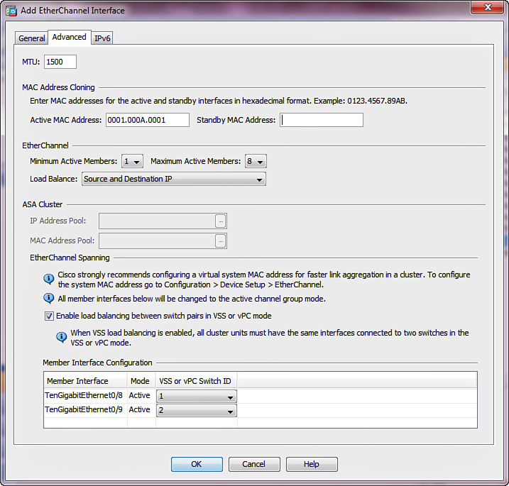
![]() MAC Address Cloning: Always configure a cluster virtual MAC address when running in the Spanned EtherChannel mode to avoid network instability on master changes. Only fill out the Active MAC Address field. Figure 16-24 sets the virtual MAC address of the interface to 0001.000A.0001.
MAC Address Cloning: Always configure a cluster virtual MAC address when running in the Spanned EtherChannel mode to avoid network instability on master changes. Only fill out the Active MAC Address field. Figure 16-24 sets the virtual MAC address of the interface to 0001.000A.0001.
![]() IP Address Pool: This option is only available for Individual mode interfaces and dedicated management-only interfaces in the Spanned EtherChannel mode. Each unit in the cluster uses one of the IP addresses from the configured pool on this interface. The master unit typically employs the first address and distributes the rest of them to the slaves based on their order of admission to the cluster. The pool must be large enough to accommodate the maximum expected number of cluster members.
IP Address Pool: This option is only available for Individual mode interfaces and dedicated management-only interfaces in the Spanned EtherChannel mode. Each unit in the cluster uses one of the IP addresses from the configured pool on this interface. The master unit typically employs the first address and distributes the rest of them to the slaves based on their order of admission to the cluster. The pool must be large enough to accommodate the maximum expected number of cluster members.
![]() MAC Address Pool: This option is only available for Individual mode interfaces and dedicated management-only interfaces in the Spanned EtherChannel mode. This configuration is optional. Otherwise, it is similar to the IP Address Pool setting.
MAC Address Pool: This option is only available for Individual mode interfaces and dedicated management-only interfaces in the Spanned EtherChannel mode. This configuration is optional. Otherwise, it is similar to the IP Address Pool setting.
![]() Enable Load Balancing Between Switch Pairs in VSS or vPC Node: This option is only available in the Spanned EtherChannel mode and is only applicable when using standby interfaces in a cluster-spanned EtherChannel. When a cluster connects to a VSS or vPC logical switch pair, cLACP can intelligently bundle cluster-spanned EtherChannel links to evenly distribute the load between the two physical switch chassis. If you check this option, you must also choose the VSS or vPC chassis identifier for each member link in the Member Interface Configuration area.
Enable Load Balancing Between Switch Pairs in VSS or vPC Node: This option is only available in the Spanned EtherChannel mode and is only applicable when using standby interfaces in a cluster-spanned EtherChannel. When a cluster connects to a VSS or vPC logical switch pair, cLACP can intelligently bundle cluster-spanned EtherChannel links to evenly distribute the load between the two physical switch chassis. If you check this option, you must also choose the VSS or vPC chassis identifier for each member link in the Member Interface Configuration area.
Example 16-22 shows the complete interface configuration from this example. Notice that this cluster is operating in Spanned EtherChannel mode.
Example 16-22 Cluster-Spanned EtherChannel Configuration
interface TenGigabitEthernet0/8
channel-group 20 mode active vss-id 1
no nameif
no security-level
no ip address
!
interface TenGigabitEthernet0/9
channel-group 20 mode active vss-id 2
no nameif
no security-level
no ip address
interface Port-channel20
port-channel span-cluster vss-load-balance
mac-address 0001.000a.0001
nameif inside
security-level 100
ip address 192.168.1.1 255.255.255.0
Monitoring and Troubleshooting Clustering
Use ASDM to monitor the health and traffic statistics of an ASA cluster from the Cluster Dashboard and Cluster Firewall Dashboard. Figure 16-25 shows a sample view of the Cluster Dashboard with two members. Click each individual unit in the Environment Status column to review the power supply and CPU temperature sensor information.
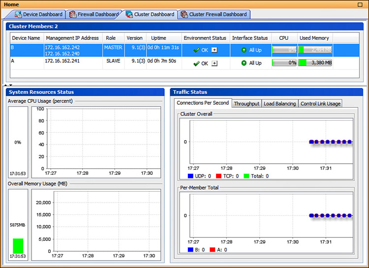
You can also issue the show cluster commands to review some aggregated cluster information. Example 16-23 reveals the available options.
Example 16-23 show cluster Command Options
asa(cfg-cluster)# show cluster ?
exec mode commands/options:
access-list Show hit counters for access policies
conn Show conn info
cpu Show CPU usage information
history Show cluster switching history
info Show cluster status
interface-mode Show cluster interface mode
memory Show system memory utilization and other information
resource Display system resources and usage
traffic Show traffic statistics
user-identity Show user-identity firewall user identities
xlate Show current translation information
Example 16-24 provides sample output of the show cluster info command. Notice that it displays the current unit roles, their software versions, CCL addressing information, and the timestamps of the last join and leave events.
Example 16-24 Monitoring Cluster Status
asa# show cluster info
Cluster sjfw: On
Interface mode: spanned
This is "B" in state MASTER
ID : 1
Version : 9.1(3)
Serial No.: JAF1511ABFT
CCL IP : 10.0.0.2
CCL MAC : 5475.d05b.26f2
Last join : 17:20:24 UTC Sep 26 2013
Last leave: N/A
Other members in the cluster:
Unit "A" in state SLAVE
ID : 0
Version : 9.1(3)
Serial No.: JAF1434AERL
CCL IP : 10.0.0.1
CCL MAC : 5475.d029.8856
Last join : 17:24:05 UTC Sep 26 2013
Last leave: 17:22:05 UTC Sep 26 2013
All subcommands under show cluster info provide important cluster subsystem information. For instance, you should periodically use the show cluster info conn-distribution and show cluster info packet-distribution commands to check how much asymmetrical traffic each cluster member is processing. Recall that a higher degree of flow asymmetry leads to lower cluster performance. If you notice too many forwarding flows or redirected packets, investigate the external load-balancing algorithms used on either side of the ASA cluster.
The show cluster info trace command is useful for debugging complex clustering issues. The output displays a historical view of cluster events, messages received on the cluster control link, and other internal clustering information. If you run any cluster debug commands, this trace log stores their outputs as well. You typically collect and interpret this information under Cisco TAC guidance.
For basic troubleshooting needs, leverage the show cluster history command instead. It provides a historical summary of the particular unit’s state transitions as well as the underlying reasons. Example 16-25 shows sample output of this command from a unit that initially disabled clustering because of an interface health check failure. Notice that the member attempted to rejoin the cluster 5 minutes later but disabled itself again. This implies that one of its interfaces remained down why other units had the same interface in an operational state.
Example 16-25 Cluster State Transition History
asa# show cluster history
==========================================================================
From State To State Reason
==========================================================================
18:57:01 UTC Sep 26 2013
SLAVE DISABLED Received control message DISABLE
19:02:02 UTC Sep 26 2013
DISABLED ELECTION Enabled from kickout timer
19:02:02 UTC Sep 26 2013
ELECTION SLAVE_COLD Received cluster control message
19:02:02 UTC Sep 26 2013
SLAVE_COLD SLAVE_CONFIG Client progression done
19:02:04 UTC Sep 26 2013
SLAVE_CONFIG SLAVE_BULK_SYNC Configuration replication finished
19:02:16 UTC Sep 26 2013
SLAVE_BULK_SYNC SLAVE Configuration replication finished
19:02:18 UTC Sep 26 2013
SLAVE DISABLED Received control message DISABLE
The corresponding syslog message from the master unit is as follows:
%ASA-3-747022: Clustering: Asking slave unit A to quit because it failed
interface health check 2 times (last failure on Port-channel2), rejoin will be
attempted after 10 min.
Notice that Port-Channel2 was the failed interface on the disabled slave unit and that the next automatic rejoin attempt occurs in 10 minutes.
Use the cluster exec command on the master unit to execute a particular global mode command on all cluster members at the same time. The master consolidates the output from the other members and displays it on the local terminal session. Example 16-26 shows aggregated output of the show port-channel summary command from all cluster members. This information allows you to monitor and troubleshoot cluster-spanned EtherChannel bundling issues.
Example 16-26 Cluster-Wide EtherChannel Information
asa# cluster exec show port-channel summary
A(LOCAL):*************************************************************
Flags: D - down P - bundled in port-channel
I - stand-alone s - suspended
H - Hot-standby (LACP only)
U - in use N - not in use, no aggregation/nameif
M - not in use, no aggregation due to minimum links not met
w - waiting to be aggregated
Number of channel-groups in use: 3
Group Port-channel Protocol Span-cluster Ports
------+-------------+---------+------------+------------------------------------
1 Po1(U) LACP No Gi0/0(P) Gi0/1(P)
2 Po2(U) LACP Yes Gi0/2(P)
3 Po3(U) LACP Yes Gi0/3(P)
B:********************************************************************
Flags: D - down P - bundled in port-channel
I - stand-alone s - suspended
H - Hot-standby (LACP only)
U - in use N - not in use, no aggregation/nameif
M - not in use, no aggregation due to minimum links not met
w - waiting to be aggregated
Number of channel-groups in use: 3
Group Port-channel Protocol Span-cluster Ports
------+-------------+---------+------------+------------------------------------
1 Po1(U) LACP No Gi0/0(P) Gi0/1(P)
2 Po2(U) LACP Yes Gi0/2(P)
3 Po3(U) LACP Yes Gi0/3(P)
Other typical uses for this command include cluster exec capture and cluster exec copy /noconfirm, which, respectively, allow you to enable a distributed packet capture and copy image files to all units simultaneously.
Spanned EtherChannel Cluster Deployment Scenario
For this scenario, assume that you are responsible for an existing data center ASA 5550 deployment that uses Active/Standby failover. Due to growing bandwidth requirements, you have made a decision to upgrade this installation to ASA 5585-X appliances with SSP-60 modules. To maximize the efficiency of your hardware investment and enable future scalability, start with a cluster of two such appliances and add more units as necessary. The old failover installation operated in single-context transparent mode, and you need to retain this design. You come up with the following plan:
![]() Deploy the cluster in multiple-context mode to extend the number of available transparent bridge groups and allow for routed mode contexts as well.
Deploy the cluster in multiple-context mode to extend the number of available transparent bridge groups and allow for routed mode contexts as well.
![]() Use the Spanned EtherChannel interface mode to support transparent contexts and simplify traffic load balancing.
Use the Spanned EtherChannel interface mode to support transparent contexts and simplify traffic load balancing.
![]() Create a “firewall-on-a-stick” topology with a single EtherChannel link to the existing vPC pair of Nexus 7000 switches. Configure this connection as a VLAN trunk with each logical data interface using a separate VLAN identifier. This data EtherChannel bundles two 10-Gigabit Ethernet interfaces from each cluster member.
Create a “firewall-on-a-stick” topology with a single EtherChannel link to the existing vPC pair of Nexus 7000 switches. Configure this connection as a VLAN trunk with each logical data interface using a separate VLAN identifier. This data EtherChannel bundles two 10-Gigabit Ethernet interfaces from each cluster member.
![]() Leverage a separate Nexus 7000 switch for the management and cluster control link connections. Each unit uses its Management0/0 interface as the dedicated management port. Each unit bundles two 10-Gigabit Ethernet interfaces for its cluster control link connection.
Leverage a separate Nexus 7000 switch for the management and cluster control link connections. Each unit uses its Management0/0 interface as the dedicated management port. Each unit bundles two 10-Gigabit Ethernet interfaces for its cluster control link connection.
![]() Configure clustering through the serial console of each unit.
Configure clustering through the serial console of each unit.
Figure 16-26 shows the proposed topology with appropriate interface connections and IP addresses on the data, management, and cluster control segments. Inside VLAN 10 transparently bridges with outside VLAN 11 as in the current deployment.
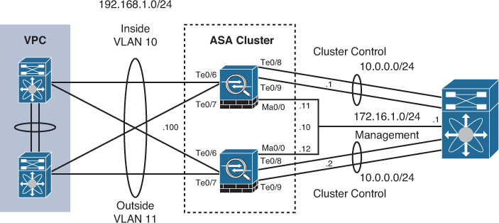
You must complete the following tasks before starting the cluster configuration process:
![]() Connect all the interfaces and configure adjacent switches. The data EtherChannel uses cLACP from the cluster side and LACP on the switch, so the member interfaces employ the mode active setting. The cluster control link EtherChannels use static bundling with the mode on setting on member interfaces.
Connect all the interfaces and configure adjacent switches. The data EtherChannel uses cLACP from the cluster side and LACP on the switch, so the member interfaces employ the mode active setting. The cluster control link EtherChannels use static bundling with the mode on setting on member interfaces.
![]() Clear the configuration of both ASA units with the clear configure all command, load the desired system and ASDM images, set the correct boot system command, switch to multiple-context mode with the mode multiple command, and enable the global jumbo-frame reservation command for the cluster control link MTU. Be sure to save the running configuration with the write memory command on each ASA and perform a reload after these steps. Because you are not using ASDM to configure clustering, you do not need to enable the appliances for HTTPS access.
Clear the configuration of both ASA units with the clear configure all command, load the desired system and ASDM images, set the correct boot system command, switch to multiple-context mode with the mode multiple command, and enable the global jumbo-frame reservation command for the cluster control link MTU. Be sure to save the running configuration with the write memory command on each ASA and perform a reload after these steps. Because you are not using ASDM to configure clustering, you do not need to enable the appliances for HTTPS access.
![]() Install permanent Cluster and Encryption-3DES-AES licenses on both prospective cluster members. An SSP-60 comes with the Security Plus license for the 10GE I/O feature by default.
Install permanent Cluster and Encryption-3DES-AES licenses on both prospective cluster members. An SSP-60 comes with the Security Plus license for the 10GE I/O feature by default.
After you have completed these prerequisites, follow these steps to create a cluster on the master unit:
1. Set the data interface mode to Spanned EtherChannel. Because you previously cleared the configuration, this operation completes without a reload.
ciscoasa# configure terminal
ciscoasa(config)# cluster interface-mode spanned
Cluster interface-mode has been changed to 'spanned' mode successfully. Please complete
interface and routing configuration before enabling clustering.
2. Create a static EtherChannel for the local cluster control link. Bundle TenGigabitEthernet0/8 and 0/9 interfaces into Port-channel1 for this purpose:
ciscoasa(config)# interface TenGigabitEthernet 0/8
ciscoasa(config-if)# channel-group 1 mode on
INFO: security-level, delay and IP address are cleared on TenGigabitEthernet0/8.
ciscoasa(config-if)# no shutdown
ciscoasa(config-if)# interface TenGigabitEthernet 0/9
ciscoasa(config-if)# channel-group 1 mode on
INFO: security-level, delay and IP address are cleared on TenGigabitEthernet0/9.
ciscoasa(config-if)# no shutdown
3. Create a new cluster group called DC-ASA:
ciscoasa(config)# cluster group DC-ASA
Notice that the system adds the following cluster group commands by default:
health-check holdtime 3
clacp system-mac auto system-priority 1
The first command enables keepalive messages on the cluster control link for basic system and interface health checking. The default hold time for failure detection is 3 seconds. You can lower this value to detect unit failures quicker, but it may lead to unexpected member dropouts under high load or minor network instabilities. Leave the default setting in this scenario.
The second command generates a virtual system cLACP identifier and sets the local LACP priority to 1 in order to support dynamic bundling with cluster-spanned EtherChannels. Do not modify this command unless you have a compelling reason to do so.
4. Configure the local unit name and master election priority under the cluster group. Call this unit terra and give it the priority of 1 to always win the master election:
ciscoasa(cfg-cluster)# local-unit terra
ciscoasa(cfg-cluster)# priority 1
5. Enable cLACP static port priority to support more than eight active member ports in the cluster-spanned EtherChannel that will be used for data VLANs. This feature is available only in ASA 9.2(1) and later Cisco ASA software.
ciscoasa(cfg-cluster)# clacp static-port-priority
Even though the initial cluster deployment includes only two ASA units with a total of four bundled data interfaces, this capability allows you to fully utilize all cluster-spanned EtherChannel members when you expand the cluster beyond four appliances in the future. You must use a switch line card that supports bundling more than eight active members in a single EtherChannel for this feature to work correctly.
6. Set Port-channel1 as the cluster control link and give this unit an IP address of 10.0.0.1 on the 10.0.0.0/24 cluster control subnet:
ciscoasa(cfg-cluster)# cluster-interface Port-channel 1 ip 10.0.0.1 255.255.255.0
INFO: Non-cluster interface config is cleared on Port-channel1
7. Encrypt system messages on the cluster control link with ClusterSecret100 as the shared key:
ciscoasa(cfg-cluster)# key ClusterSecret100
8. Because all data interfaces use the IP MTU of 1500 bytes, set the MTU value for the cluster control link to 1600 bytes:
ciscoasa(cfg-cluster)# mtu cluster 1600
9. Return to the cluster group configuration mode and enable clustering. The system checks the current configuration for incompatible commands and prompts you before removing them. In this case, some default application inspection configuration statements in the admin context are not compatible with clustering. After removing these commands, the unit holds the election and transitions to the master role.
ciscoasa(config)# cluster group DC-ASA
ciscoasa(cfg-cluster)# enable
INFO: Clustering is not compatible with following commands:
Context: admin
===============================
policy-map global_policy
class inspection_default
inspect h323 h225
policy-map global_policy
class inspection_default
inspect h323 ras
policy-map global_policy
class inspection_default
inspect rtsp
policy-map global_policy
class inspection_default
inspect skinny
policy-map global_policy
class inspection_default
inspect sip
Would you like to remove these commands? [Y]es/[N]o: y
INFO: Removing incompatible commands from running configuration...
Cryptochecksum (changed): 876692b4 bc9fe109 06d4724f 4d7b8608
INFO: Done
WARNING: dynamic routing is not supported on management interface when cluster
interface-mode is 'spanned'. If dynamic routing is configured on any management
interface, please remove it.
Cluster unit terra transitioned from DISABLED to MASTER
Now follow these steps to configure the dedicated management interface:
1. Enable the Management0/0 interface and assign it to the admin context:
ciscoasa(config-if)# interface Management0/0
ciscoasa(config-if)# no shutdown
ciscoasa(config-if)# context admin
ciscoasa(config-ctx)# allocate-interface Management0/0
2. Move to the admin context to configure the management interface IP addressing:
ciscoasa(config-ctx)# changeto context admin
3. The dedicated management interface in Spanned EtherChannel mode uses a pool of IP addresses, so that you can access each individual cluster member directly. Create a pool of IP addresses on the management subnet. The current master takes the first address in this pool and then assigns the rest of the addresses to slave units in the order of their admission to the cluster. These assignments do not change unless a unit leaves the cluster. The master also responds to the virtual cluster IP address on this interface.
In this case, use 172.16.1.10 as the virtual cluster address for the management interface and 172.16.1.11 through 172.16.1.18 for the dynamic pool to support up to eight cluster members:
ciscoasa/admin(config)# ip local pool CLUSTER_MANAGEMENT 172.16.1.11-172.16.1.18
4. Configure the dedicated management interface:
ciscoasa/admin(config)# interface Management0/0
ciscoasa/admin(config-if)# management-only
ciscoasa/admin(config-if)# nameif Management
INFO: Security level for "Management" set to 0 by default.
ciscoasa/admin(config-if)# security-level 100
ciscoasa/admin(config-if)# ip address 172.16.1.10 255.255.255.0 cluster-pool CLUSTER_MANAGEMENT
Now proceed to configuring the data interfaces:
1. Change back to the system context:
ciscoasa/admin(config-if)# changeto system
2. Configure member interfaces for the data EtherChannel. Bundle TenGigabitEthernet0/6 and 0/7 into Port-channel10 for this purpose. Even though you connect the cluster to a vPC logical switch, you do not need to specify the physical chassis identifier for each EtherChannel member connection because you intend to bundle more than eight active interfaces. If you did not enable cLACP static port priority under the cluster group configuration, you need to add vss-id 1 and vss-id 2 arguments to the respective channel-group statements to ensure proper active port distribution between the physical switch chassis.
ciscoasa(cfg-cluster)# interface TenGigabitEthernet 0/6
ciscoasa(config-if)# channel-group 10 mode active
ciscoasa(config-if)# no shutdown
ciscoasa(config-if)# interface TenGigabitEthernet 0/7
ciscoasa(config-if)# channel-group 10 mode active
ciscoasa(config-if)# no shutdown
3. Configure the Port-channel10 interface as a cluster-spanned EtherChannel. Because you intend to bundle more than eight active interfaces, do not enable vPC load balancing with the vss-load-balance argument after the port-channel span-cluster command. You need to add this argument only if you did not enable cLACP static port priority under the cluster group configuration.
ciscoasa(config-if)# interface Port-channel10
ciscoasa(config-if)# port-channel span-cluster
WARNING: Strongly recommend to configure a virtual MAC address for span-
cluster port-channel interface Po10 or all its subinterfaces in order to
achieve best stability of span-cluster port-channel during unit join/leave.
INFO: lacp port-priority on member interfaces of channel-group Port-channel10 will be controlled by CLACP.
Because you are using multiple-context mode, configure virtual MAC addresses under the individual logical interfaces in each application context.
4. Create subinterfaces for the data VLANs under the cluster-spanned EtherChannel and assign them to a new context called Core. This context operates in transparent mode and matches the existing data center firewall design.
ciscoasa(config-if)# interface Port-channel 10.10
ciscoasa(config-subif)# vlan 10
ciscoasa(config-subif)# interface Port-channel 10.11
ciscoasa(config-subif)# vlan 11
ciscoasa(config-subif)# context Core
Creating context 'Core'... Done. (2)
ciscoasa(config-ctx)# config-url core.cfg
INFO: Converting core.cfg to disk0:/core.cfg
ciscoasa(config-ctx)# allocate-interface Port-channel10.10
ciscoasa(config-ctx)# allocate-interface Port-channel10.11
5. Move to the Core context to complete the data interface configuration:
ciscoasa(config-ctx)# changeto context Core
6. Change the context to transparent firewall mode:
ciscoasa/Core(config)# firewall transparent
7. Configure VLAN 10 as the inside interface and VLAN 11 as the outside interface. Add them to bridge group 1. Use virtual MAC addresses 0001.000A.0001 and 0001.000A.0002 respectively to protect against network instabilities when the master unit changes.
ciscoasa/Core(config)# interface Port-channel 10.10
ciscoasa/Core(config-if)# nameif inside
INFO: Security level for "inside" set to 100 by default.
ciscoasa/Core(config-if)# bridge-group 1
ciscoasa/Core(config-if)# mac-address 0001.000A.0001
ciscoasa/Core(config-if)# interface Port-channel 10.11
ciscoasa/Core(config-if)# nameif outside
INFO: Security level for "outside" set to 0 by default.
ciscoasa/Core(config-if)# bridge-group 1
ciscoasa/Core(config-if)# mac-address 0001.000A.0002
8. Configure the Bridge-Group Virtual Interface (BVI) for this bridge group. Use 192.168.1.100 as the cluster virtual IP address for this BVI. The cluster employs this IP address for MAC address discovery and management purposes.
ciscoasa/Core(config)# interface BVI 1
ciscoasa/Core(config-if)# ip address 192.168.1.100 255.255.255.0
9. Proceed with configuring other security policies.
After the configuration of the master unit is complete, add the slave unit to the cluster using these steps:
1. Set the data interface mode to Spanned EtherChannel. Similarly to the master unit, a reload is not required.
ciscoasa# configure terminal
ciscoasa(config)# cluster interface-mode spanned
Cluster interface-mode has been changed to 'spanned' mode successfully. Please complete interface and routing configuration before enabling clustering.
2. Create a static EtherChannel for the local cluster control link. Bundle TenGigabitEthernet0/8 and 0/9 interfaces into Port-channel1 to match the master unit:
ciscoasa(config)# interface TenGigabitEthernet 0/8
ciscoasa(config-if)# channel-group 1 mode on
INFO: security-level, delay and IP address are cleared on TenGigabitEthernet0/8.
ciscoasa(config-if)# no shutdown
ciscoasa(config-if)# interface TenGigabitEthernet 0/9
ciscoasa(config-if)# channel-group 1 mode on
INFO: security-level, delay and IP address are cleared on TenGigabitEthernet0/9.
ciscoasa(config-if)# no shutdown
3. Specify the cluster group name to match the existing cluster:
ciscoasa(config)# cluster group DC-ASA
4. Configure the local unit name and master election priority under the cluster group. Call this unit sirius and give it the priority of 100 to avoid becoming the master when possible:
ciscoasa(cfg-cluster)# local-unit sirius
ciscoasa(cfg-cluster)# priority 100
5. Set Port-channel1 as the cluster control link and give this unit an IP address of 10.0.0.2 on the 10.0.0.0/24 cluster control subnet to match the existing master:
ciscoasa(cfg-cluster)# cluster-interface Port-channel 1 ip 10.0.0.2 255.255.255.0
INFO: Non-cluster interface config is cleared on Port-channel1
6. Set the shared encryption key to match the master unit:
ciscoasa(cfg-cluster)# key ClusterSecret100
7. All other configuration automatically synchronizes from the master unit, so you can just enable clustering and follow the prompts:
ciscoasa(cfg-cluster)# enable
INFO: Clustering is not compatible with following commands:
Context: admin
===============================
policy-map global_policy
class inspection_default
inspect h323 h225
policy-map global_policy
class inspection_default
inspect h323 ras
policy-map global_policy
class inspection_default
inspect rtsp
policy-map global_policy
class inspection_default
inspect skinny
policy-map global_policy
class inspection_default
inspect sip
Would you like to remove these commands? [Y]es/[N]o: y
INFO: Removing incompatible commands from running configuration...
Cryptochecksum (changed): 876692b4 bc9fe109 06d4724f 4d7b8608
INFO: Done
WARNING: Strongly recommend to configure a virtual MAC address for each span-cluster
port-channel interface or all subinterfaces of it in order to achieve best stability of
span-cluster port-channel during unit join/leave.
Detected Cluster Master.
Beginning configuration replication from Master.
INFO: UC proxy will be limited to maximum of 4 sessions by the UC Proxy license on the device
WARNING: Removing all contexts in the system
Removing context 'admin' (1)... Done
Creating context 'admin'... Done. (3)
Creating context 'Core'... Done. (4)
INFO: Interface MTU should be increased to avoid fragmenting
jumbo frames during transmit
*** Output from config line 92, "jumbo-frame reservation"
Cryptochecksum (changed): d430074f 5758018b f3543519 107be1fa
Cryptochecksum (changed): 9965fb60 dce9ae61 20973a4e 2a386323
Cryptochecksum (changed): e74433ae 5f4b0324 67ab30c4 ce805222
End configuration replication from Master.
Cluster unit sirius transitioned from DISABLED to SLAVE
Use the show cluster info command on the master unit to verify that the cluster is operational:
ciscoasa# show cluster info
Cluster DC-ASA: On
Interface mode: spanned
This is "terra" in state MASTER
ID : 0
Version : 9.2(1)
Serial No.: JAF1434AERL
CCL IP : 10.0.0.1
CCL MAC : 5475.d029.8856
Last join : 09:26:37 UTC Sep 27 2013
Last leave: N/A
Other members in the cluster:
Unit "sirius" in state SLAVE
ID : 1
Version : 9.2(1)
Serial No.: JAF1511ABFT
CCL IP : 10.0.0.2
CCL MAC : 5475.d05b.26f2
Last join : 10:42:37 UTC Sep 27 2013
Last leave: 10:28:29 UTC Sep 27 2013
Example 16-27 shows the full system and context configuration from the cluster master.
Example 16-27 Complete Cluster Configuration on Master Unit
! *** System context ***
interface TenGigabitEthernet0/6
channel-group 10 mode active
!
interface TenGigabitEthernet0/7
channel-group 10 mode active
!
interface TenGigabitEthernet0/8
channel-group 1 mode on
!
interface TenGigabitEthernet0/9
channel-group 1 mode on
!
interface Port-channel1
description Clustering Interface
!
interface Port-channel10
port-channel span-cluster
!
interface Port-channel10.10
vlan 10
!
interface Port-channel10.11
vlan 11
!
cluster group DC-ASA
local-unit terra
cluster-interface Port-channel1 ip 10.0.0.1 255.255.255.0
priority 1
key ClusterSecret100
health-check holdtime 3
clacp system-mac auto system-priority 1
clacp static-port-priority
enable
!
mtu cluster 1600
!
admin-context admin
context admin
allocate-interface Management0/0
config-url disk0:/admin.cfg
!
context Core
allocate-interface Port-channel10.10-Port-channel10.11
config-url disk0:/core.cfg
!
jumbo-frame reservation
!
! *** Admin context ***
ip local pool CLUSTER_MANAGEMENT 172.16.1.11-172.16.1.18
!
interface Management0/0
management-only
nameif Management
security-level 100
ip address 172.16.1.10 255.255.255.0 cluster-pool CLUSTER_MANAGEMENT
!
! *** Core context ***
firewall transparent
!
interface BVI1
ip address 192.168.1.100 255.255.255.0
!
interface Port-channel10.10
mac-address 0001.000a.0001
nameif inside
bridge-group 1
security-level 100
!
interface Port-channel10.11
mac-address 0001.000a.0002
nameif outside
bridge-group 1
security-level 0
Summary
Cisco ASA offers a myriad of high availability and scalability options to satisfy all kinds of design requirements. This chapter showed how to leverage redundant interfaces for basic physical link redundancy when the bandwidth requirements do not justify the complexity of an EtherChannel. It explained how static route tracking with IP SLA monitor allows you to deploy backup ISP interfaces with dynamic switchover. It reviewed how to use Active/Standby and Active/Active failover to implement a fully redundant configuration between a pair of ASA appliances or Services Modules. The discussion also introduced clustering that enables elastic performance scalability and maximizes your hardware investment with up to 16 appliances in a single traffic processing system. The examples emphasized how both failover and clustering allow the ASA to effectively serve as a redundant first-hop router for your endpoints.