Chapter 5. System Maintenance
This chapter covers the following topics:
In Chapter 4, “Initial Setup,” you learned how to connect to the Cisco Adaptive Security Appliance (ASA) via the CLI or the GUI. This chapter provides guidance on how to manage the security appliance and shows examples of how to monitor the overall system’s health and status.
Configuration Management
This section explains how to manage the configuration files on the Cisco ASA. The security appliance keeps two copies of the configuration in the system:
![]() The active, or running, configuration
The active, or running, configuration
![]() The saved, or startup, configuration
The saved, or startup, configuration
These configurations are discussed in the following subsections, followed by instructions on how to remove configurations from the security appliance.
Running Configuration
The running configuration is the actual configuration that the security appliance has loaded in its memory. When the security appliance boots up, it copies the saved configuration to its running memory and then uses it to function as designed. Use the show running-config or write terminal command to display the current configuration that the security appliance is using. These are the most important commands to verify that the security appliance is configured properly. The running configuration is not saved in nonvolatile RAM (NVRAM) until the security appliance is instructed to store it there.
Example 5-1 shows the current configuration on an appliance via the CLI. The configuration file can be fairly large and complex, depending on the number of features designed on the security appliance. The configuration file displays the current version of the system image and the remaining configuration parameters. If you prefer to see the same configuration via ASDM, choose File > Show Running Configuration in New Window. ASDM launches a new window in the default browser to show the running configuration.
Example 5-1 Output of show running-config
Chicago# show running-config
: Saved
:
ASA Version 9.1(4)
!
hostname Chicago
domain-name securemeinc.org
enable password 9jNfZuG3TC5tCVH0 encrypted
passwd 2KFQnbNIdI.2KYOU encrypted
names
!
interface GigabitEthernet0/0
nameif outside
security-level 0
ip address 209.165.200.225 255.255.255.224
!
interface GigabitEthernet0/1
nameif inside
security-level 100
ip address 192.168.10.1 255.255.255.0
!
<some output removed for brevity>
!
interface Management0/0
nameif management
security-level 100
ip address 172.18.82.75 255.255.255.0
management-only
!
ftp mode passive
pager lines 24
mtu outside 1500
mtu inside 1500
mtu management 1500
no failover
icmp unreachable rate-limit 1 burst-size 1
asdm image disk0:/asdm-715.bin
timeout xlate 3:00:00
timeout conn 1:00:00 half-closed 0:10:00 udp 0:02:00 icmp 0:00:02
timeout sunrpc 0:10:00 h323 0:05:00 h225 1:00:00 mgcp 0:05:00 mgcp-pat 0:05:00
timeout sip 0:30:00 sip_media 0:02:00 sip-invite 0:03:00 sip-disconnect 0:02:00
timeout sip-provisional-media 0:02:00 uauth 0:05:00 absolute
timeout tcp-proxy-reassembly 0:01:00
http server enable
http 172.18.82.0 255.255.255.0 management
no snmp-server location
no snmp-server contact
snmp-server enable traps snmp authentication linkup linkdown coldstart
Telnet timeout 5
console timeout 0
policy-map global_policy
class inspection_default
inspect dns preset_dns_map
inspect ftp
inspect h323 h225
inspect h323 ras
inspect rsh
inspect rtsp
inspect esmtp
inspect sqlnet
inspect skinny
inspect sunrpc
inspect xdmcp
inspect sip
inspect netbios
inspect tftp
!
service-policy global_policy global
prompt hostname context
Cryptochecksum:b1161684d23e24b33e29fe4e8b1a2b09
: end
Cisco ASA allows you to display specific parts of the configuration by using show running-config, followed by the name of the command you are interested in checking. As shown in Example 5-2, the show running-config ? command shows all possible keywords you can use, and the show running-config interface GigabitEthernet0/0 command shows the running configuration of the GigabitEthernet0/0 interface.
Example 5-2 Partial Output of show running-config
Chicago# show running-config ?
aaa Show aaa configuration information
aaa-server Show aaa-server configuration information
access-group Show access group(s)
access-list Show configured access control elements
alias Show configured overlapping addresses with dual NAT
all Current operating configuration including defaults
arp Show configured arp entries, arp timeout
asdm Show ASDM configuration
<Output omitted for brevity>
Chicago# show running-config interface GigabitEthernet0/0
!
interface GigabitEthernet0/0
nameif outside
security-level 0
ip address 209.165.200.225 255.255.255.224
Tip
The show running-config command does not display all security appliance commands set to their default values. Use show running-config all to display the entire running configuration.
The Cisco ASA operating system enables you to enhance the search capabilities when a show command is executed, by using | grep at the end of the command. Alternatively, | include displays the output when the exact phrase matches a show command. You can also use | exclude to ignore lines that match a particular phrase. Example 5-3 specifically illustrates the IP addresses configuration on the security appliance and the respective subnet masks in the running configuration.
Example 5-3 Selective Output of show running-config
Chicago# show running-config | include ip address
ip address 209.165.200.225 255.255.255.224
ip address 192.168.10.1 255.255.255.0
no ip address
no ip address
ip address 172.18.82.75 255.255.255.0
The security appliance can also display the selective output of a show command when the | begin option is used. In this case, the security appliance displays the output beginning from a specific keyword. Example 5-4 looks at the running configuration beginning from the physical interfaces. Use the show running-config | begin interface command to accomplish this.
Example 5-4 Output of show running-config Beginning from the Interface Configuration
Chicago# show running-config | begin interface
interface GigabitEthernet0/0
nameif outside
security-level 0
ip address 209.165.200.225 255.255.255.224
!
interface GigabitEthernet0/1
nameif inside
security-level 100
ip address 192.168.10.1 255.255.255.0
!
interface GigabitEthernet0/2
shutdown
no nameif
no security-level
no ip address
! Output omitted for brevity
Startup Configuration
During the bootup process, the security appliance uses the saved configuration as the running configuration. This saved configuration is known as the startup configuration. View the startup configuration by using the show startup-config or show configuration command, as shown in Example 5-5.
Example 5-5 Output of show startup-config
Chicago# show startup-config
: Saved
: Written by cisco at 21:13:44.064 CDT Fri Dec 22 2013
!
ASA Version 9.1(4)
!
hostname Chicago
domain-name securemeinc.org
enable password 9jNfZuG3TC5tCVH0 encrypted
passwd 2KFQnbNIdI.2KYOU encrypted
names
!
interface GigabitEthernet0/0
nameif outside
security-level 0
ip address 209.165.200.225 255.255.255.224
!
interface GigabitEthernet0/1
nameif inside
security-level 100
ip address 192.168.10.1 255.255.255.0
! Output omitted for brevity
The output of show running-config and show startup-config may or may not be identical, depending on whether the two configurations were synced. Use the copy running-config startup-config or write memory command to copy the active configuration into NVRAM, as shown in Example 5-6.
Example 5-6 Output of copy running-config startup-config
Chicago# copy running-config startup-config
Source filename [running-config]?
Cryptochecksum: 28b8d710 e2eaeda0 bc98a262 2bf3247a
3205 bytes copied in 3.230 secs (1068 bytes/sec)
Using ASDM, save the running configuration as the startup configuration by choosing File > Save Running Configuration to Flash.
Removing the Device Configuration
If you use ASDM, you can remove any configured feature by selecting that feature and deleting it or changing the values to their defaults. For example, if you created a sub-interface on Gigabit-Ethernet0/0, you can remove that subinterface by selecting it and then clicking the Delete button.
Using the CLI, remove a configured command from the configuration by using the no form of the command. This undoes the command that was previously entered into the configuration. In Example 5-7, the security appliance is set up for IKEv1 processing on the outside interface. It is being removed with the no crypto ikev1 enable outside command.
Example 5-7 Disabling IKEv1 Processing on the Outside Interface
Chicago(config)# crypto ikev1 enable outside
Chicago(config)# no crypto ikev1 enable outside
The security appliance can also remove the current configuration for a specific feature if the clear configure command is used. If the security appliance is set up with an ikev1 policy 10 for Phase 1 IPsec negotiations, the clear configure crypto ikev1 command removes all the ikev1 commands from the running configuration. This is demonstrated in Example 5-8.
Example 5-8 Clearing All ikev1 Commands from the Running Configuration
Chicago(config)# show running-config | include ikev1
crypto ikev1 enable outside
crypto ikev1 policy 10
Chicago(config)# clear configure crypto ikev1
Chicago(config)# show running-config | include ikev1
Note
The use of no in a command removes a single line, whereas clear configure removes the parts of the configuration for a feature.
Example 5-8 not only cleared the IKEv1 policy, but also removed the crypto ikev1 enable outside command from the running configuration. Use the clear configure crypto ikev1 policy command to remove only the IKEv1 policy from the active configuration.
Unlike a Cisco IOS router, the Cisco ASA can clear the running configuration without going through the reboot process. This is helpful in a scenario where the security appliance needs to be put in the default configuration. Use the clear configure all command to clear the running configuration, as shown in Example 5-9.
Example 5-9 Clearing the Running Configuration
Chicago(config)# clear configure all
ciscoasa(config)#
Warning
The use of the clear configure all command disconnects your link if your connection to the security appliance uses a remote-management protocol such as SSH (Secure Shell). Make sure that you are connected to the ASA via console before you issue this command.
With ASDM, you can also clear the entire configuration of a security appliance by choosing File > Reset Device to the Factory Default Configuration. ASDM prompts you to configure an IP address on the management interface. You can reestablish your ASDM connection to this IP address.
Note
You can use the configure factory-default command to load the default configuration back into the security appliance. Refer to Chapter 4 to learn more about the default configuration on a security appliance.
The security appliance can also erase the startup configuration from NVRAM if the write erase command is issued from privileged mode, as shown in Example 5-10.
Example 5-10 Clearing the Startup Configuration
Chicago# write erase
Chicago#
Tip
Cisco ASDM allows you to back up the configuration, certificates, XML files, SSL VPN customized files, and CSD/AnyConnect images. You can restore them in a different security appliance if you are configuring both appliances identically. Navigate to Tools > Backup Configurations to start the backup process.
Remote System Management
You do not have to be physically connected to the console port of the security appliance to access the CLI. The security appliance supports three remote-management protocols:
![]() ASDM (GUI over HTTPS)
ASDM (GUI over HTTPS)
As mentioned earlier, ASDM is discussed throughout this book. The other two remote-management protocols are discussed next.
Telnet
Cisco ASA comes with a Telnet server that enables you to manage it remotely via the CLI. The default behavior of the security appliance is to deny Telnet access from all clients unless they are explicitly permitted.
Note
The communication between a client and the security appliance is not encrypted; therefore, it is highly recommended to use SSH rather than Telnet for remote device management.
You may choose to enable Telnet on all interfaces. However, the security appliance does not allow clear-text Telnet communication on the outside interface unless the session is protected by an IPsec tunnel. The security appliance requires you to establish an IPsec tunnel to the outside interface to encrypt the traffic destined to the security appliance. After the tunnel is successfully negotiated, you can start a Telnet session to the outside interface.
When a Telnet client tries to connect, the security appliance verifies the following two conditions:
![]() The client’s IP address falls in the allowed address space.
The client’s IP address falls in the allowed address space.
![]() The interface that is receiving the request is allowed to accept requests from the client’s address space.
The interface that is receiving the request is allowed to accept requests from the client’s address space.
If either one of the conditions is not valid, the security appliance simply drops the request and generates a syslog message for this incident. Syslogs are discussed later in this chapter.
An external authentication server, such as Cisco Secure Access Control Server (ACS), can be used to authenticate the Telnet sessions. Consult Chapter 7, “Authentication, Authorization, and Accounting (AAA) Services,” for more information.
Configure the security appliance to accept Telnet sessions on an interface by navigating to Configuration > Device Management > Management Access > ASDM/HTTPS/Telnet/SSH and clicking Add. ASDM prompts you to select the following:
![]() Interface name from which the Telnet clients will be connecting
Interface name from which the Telnet clients will be connecting
![]() IP address of the hosts or a network address that is allowed to connect to the selected interface
IP address of the hosts or a network address that is allowed to connect to the selected interface
![]() Mask of the allowed IP or subnet address
Mask of the allowed IP or subnet address
In Figure 5-1, the management network, 172.18.82.0/24, is allowed to establish Telnet sessions to the security appliance’s management interface.

Example 5-11 shows the relevant configuration for this setup. If the Telnet connection is idle, the security appliance is set up to time it out after 5 minutes, which is the default timeout.
Example 5-11 Configuration of Telnet Access on the Management Interface
Chicago# configure terminal
Chicago(config)# telnet 172.18.82.0 255.255.255.0 management
Chicago(config)# telnet timeout 5
If a machine’s IP address is allowed to connect, the security appliance goes through the user authentication phase and prompts you for login credentials. Beginning with Cisco ASA Software version 9.0(2), there is no default Telnet password. Use the password command to set a Telnet password. Consult Chapter 4 to learn how to change the Telnet password.
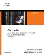
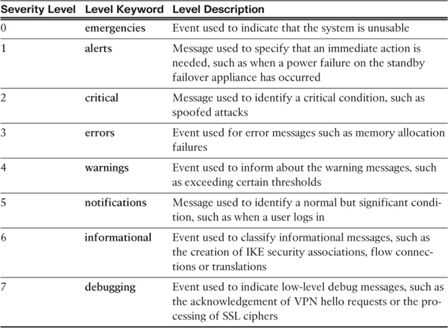
If the authentication is successful, the security appliance grants user mode CLI access to the authenticated user. Monitor the active Telnet sessions by going to Monitoring > Properties > Device Access > ASDM/HTTPS/Telnet/SSH Sessions. This displays the Telnet connection ID along with the client’s IP address. Use the connection ID to clear out a session if you believe that it should not be established. You do so by selecting the user and clicking the disconnect button.
In Figure 5-2, the security appliance has assigned a connection ID of 0 to a Telnet client 172.18.82.77. An ASDM session is also established from the same client IP address.
Example 5-12 shows the relevant configuration for this setup. A Telnet session is built from 172.18.82.77. This connection is being disconnected by use of the kill command.
Example 5-12 Monitoring and Clearing Active Telnet Sessions
Chicago# configure terminal
Chicago# who
0: 172.18.82.77
Chicago# kill 0
Chicago# who
Chicago#
Secure Shell (SSH)
SSH is the recommended way to connect to the security appliance for remote management because the data packets are encrypted by industry-standard algorithms such as 3DES and AES. The SSH implementation on the security appliance supports both version 1 and 2.
Before the SSH client and the Cisco ASA SSH server encrypt data, they go through an exchange of RSA security keys. These keys are used to ensure that an unauthorized user cannot look at the packet content. When a client tries to connect, the security appliance presents its public keys to the client. After receiving the keys, the client generates a random key and encrypts it, using the public key sent by the security appliance. These encrypted client keys are sent to the security appliance, which decodes them using its own private keys. This completes the key exchange phase, and the security appliance starts the user authentication phase. Cisco ASA supports a number of security algorithms, listed in Table 5-1.

Note
Unlike Telnet, Cisco ASA allows you to terminate SSH sessions on the outside interface. SSH sessions are already encrypted and do not require an IPsec tunnel.
To configure SSH on the security appliance, follow these steps:
1. Generate the RSA keys. The SSH daemon on the security appliance uses the RSA keys to encrypt the sessions. Generate the public and private key pair by going to Configuration > Device Management > Certificate Management > Identity Certificates > Add > Add a New Identity Certificate and selecting New for Key Pair. Alternatively, you can use the crypto key generate rsa command from the CLI as shown in the following output. For detailed information about generating the RSA keys, consult Chapter 21, “Configuring and Troubleshooting Public Key Infrastructure (PKI).”
Chicago(config)# crypto key generate rsa
INFO: The name for the keys will be: <Default-RSA-Key>
Keypair generation process begin. Please wait...
You can change the default modulus size, 1024 bits, to 512, 768, 2048, or 4096 bits. After the keys have been generated, view the public keys by using the show crypto key mypubkey rsa command:
Chicago(config)# show crypto key mypubkey rsa
Key pair was generated at: 22:41:07 UTC Dec 21 2013
Key name: <Default-RSA-Key>
Usage: General Purpose Key
Modulus Size (bits): 1024
Key Data:
30819f30 0d06092a 864886f7 0d010101 05000381 8d003081 89148181 00b85a0c
7af04bc1 028c072e 4be49fad 29e7c8e2 9b1341cc e6ace229 2556b310 66a12627
05166501 30ca3360 e32307d7 31d2f839 7a36005e 0656cc36 4fa23aa5 7d9a3f09
fd5b35b2 cdf1b393 8e4ba10f 0752f2ec c29915cf f058945a 4ac11cd6 d46c72d7
a45766e1 851d1093 e1cd4a93 f222631f 6c51a55f e9ef229a 4481f719 55020301 0001
2. Enable SSH on an interface.
Configure the security appliance to accept SSH sessions on an interface by navigating to Configuration > Device Management > Management Access > ASDM/HTTPS/Telnet/SSH and clicking Add. ASDM prompts you to select an interface name and specify the IP address/mask, similar to what was covered in the Telnet section. As shown in the following example, the security appliance is configured to accept SSH sessions from the 172.18.82.0/24 network that is connected off of the management interface:
Chicago(config)# ssh 172.18.82.0 255.255.255.0 management
Once SSH is enabled on an interface, you can initiate an SSH connection as long as the IP address is in the allowed list. After the client and the security appliance negotiate the security parameters, the security appliance prompts you for authentication credentials. If the authentication is successful, you are put into user access mode.
For SSH connection, there is no default username or password in the software version-8.4(2) and later. You must configure the aaa authentication ssh console command to enable AAA authentication.
3. (Optional) Restrict the SSH version.
The security appliance can restrict a client to use either SSH version 1 (SSHv1) or SSH version 2 (SSHv2) when a connection is made. By default, the security appliance accepts both versions. SSHv2 is the recommended version because of its strong authentication and encryption capabilities. However, the security appliance does not provide support for the following SSHv2 features:
![]() X11 forwarding
X11 forwarding
![]() Port forwarding
Port forwarding
![]() Secure File Transfer Protocol (SFTP) support
Secure File Transfer Protocol (SFTP) support
![]() Kerberos and AFS ticket passing
Kerberos and AFS ticket passing
![]() Data compression
Data compression
In ASDM, select the SSH version from the Allowed SSH Version(s) drop-down menu. To set a specific SSH version via the CLI, use the ssh version command, followed by the actual version of the shell.
Note
The security appliance must have the 3DES-AES feature set in the license to support SSHv2 sessions.
4. (Optional) Modify the idle timeout.
Similar to the Telnet timeout, you can fine-tune the idle timeout value between 1 and 60 minutes. If the organizational security policy does not allow long idle connections, the idle timeout value can be changed to a lower value, such as 3 minutes, from its default value of 5 minutes.
5. Monitor the SSH sessions.
As with Telnet sessions, monitor the SSH session by going to Monitoring > Properties > Device Access > ASDM/HTTPS/Telnet/SSH Sessions. This displays useful information such as the username, IP address of the client, encryption and hashing used, the current state of the connection, and the SSH version that is used. You can also use the show ssh session command from the CLI to get similar information.
If you need to manually disconnect an active SSH session, click the Disconnect button. CLI admins can issue the ssh disconnect command followed by the session ID number.
6. Enable Secure Copy (SCP). You can use the SCP file transfer protocol to move files to the network device securely. It functions similarly to FTP but with the added advantage of data encryption. The security appliance can act as an SCP server to allow SSHv2 clients to copy files in flash. SCP can be enabled by navigating to Configuration > Device Management > Management Access > File Access > Secure Copy (SCP) Server and selecting Enable Secure Copy Server. If you prefer to use the CLI, use the ssh scopy enable command as follows:
Chicago(config)# ssh scopy enable
Note
The SSH client must be SCP capable to be able to transfer files.
System Maintenance
This section explains how to manage and install a different system image file on the Cisco ASA and ways to recover a device with no operating system. This section also discusses how to recover authentication passwords if they are lost.
Software Installation
The Cisco ASA supports upgrading a system image file to flash via both the Cisco ASDM and the Cisco ASA CLI.
In case the security appliance does not have a bootable image, this section also discusses steps to upload the image from ROMMON.
Image Upgrade via Cisco ASDM
ASDM can upload either an ASA or an ASDM image to the Cisco ASA flash using HTTPS. ASDM gives you two options to upgrade the software versions:
![]() Choose Tools > Upgrade Software from Local Computer to upload a file from the local computer to the local flash of Cisco ASA.
Choose Tools > Upgrade Software from Local Computer to upload a file from the local computer to the local flash of Cisco ASA.
![]() Choose Tools > Check for ASA/ASDM Updates to check Cisco’s website for the latest version of the ASA/ASDM binary image.
Choose Tools > Check for ASA/ASDM Updates to check Cisco’s website for the latest version of the ASA/ASDM binary image.
In most cases, you want to download a bootable image from Cisco.com to your local workstation. Many enterprises prefer to test an ASA image in their lab environment first to make sure that the new image fits their requirements.
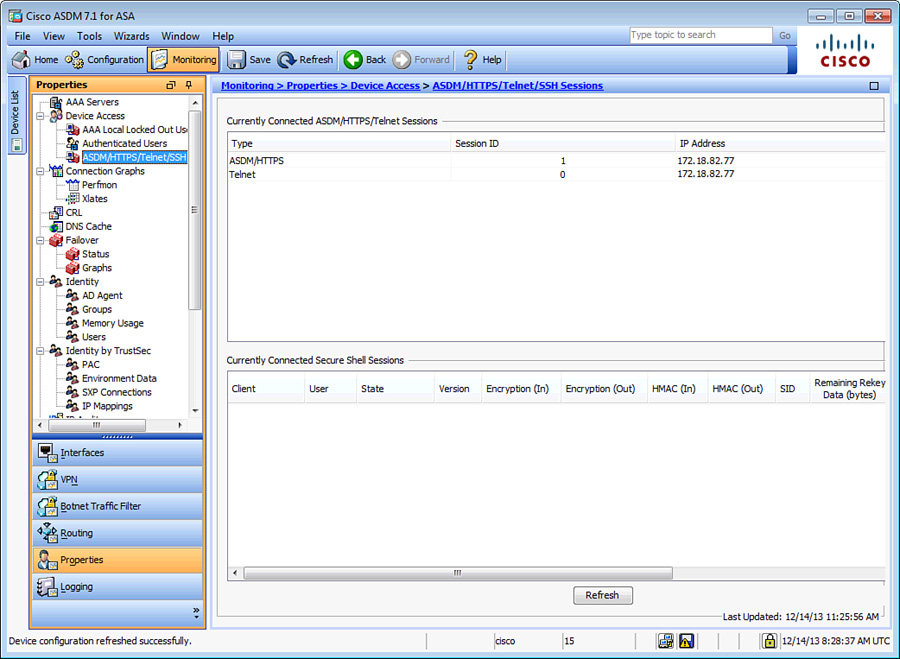
If you choose Upgrade Software from Local Computer, select whether you want to upload an ASDM or an ASA image, and then specify the path to the image file on the local drive. For ease of use, click Browse Local Files and select the file by searching the local hard-drive file structure. Specify the destination location on the Cisco ASA flash and then click Upload Image to initiate the file transfer process, as shown in Figure 5-3.
If the system flash contains more than one system image, the Cisco ASA boots using the first image it finds in flash. If the image you want to boot is not the first one on the disk, set the boot order to load the desired binary image file. Navigate to Configuration > Device Administration > System Image/Configuration > Boot Image/Configuration > Add > Browse Flash and select the image that you want to boot. If you have selected multiple images to boot from, change the priority of a particular image by clicking the Move Up and Move Down buttons.
After a new image has been uploaded, you must reboot the appliance to load the new image. You do so by choosing Tools > System Reload. Cisco ASDM prompts you to indicate whether you want to save the running configuration in the NVRAM and whether you want to reload now or schedule a time to reboot later. If you made changes to the order of bootable images, it is important to save the configuration prior to reloading the Cisco ASA.
Image Upgrade via the Cisco ASA CLI
The security appliance supports a number of file server types, including TFTP, HTTP(s), SMB, and FTP, to download a system image into flash (disk0). The image upgrade process uses the copy command followed by the name of the file transfer type. The copy command duplicates the specified files from the source location or URL to the destination location (flash). The destination location of the system image is the local file system. The security appliance has an internal storage disk, referred to as disk0: or flash. Additionally, an external storage device, referred to as disk1:, can be used to save system images.
Use the noconfirm option to notify the security appliance to accept the parameters without prompting you for confirmation. This is helpful if customized scripts are used to upload system images.
Example 5-13 illustrates how to configure the security appliance to download an image file, called asa914-smp-k8.bin, from a TFTP server located at 172.18.82.10. The security appliance initiates the download process and stores the image file as asa914-smp-k8.bin.
Example 5-13 Copying a System Image from a TFTP Server to the Local Flash
Chicago# copy tftp: flash:
Address or name of remote host []? 172.18.82.10
Source filename []? asa914-smp-k8.bin
Destination filename [asa914-smp-k8.bin]? asa914-smp-k8.bin
Accessing tftp://172.18.82.10/asa914-smp-k8.bin...!!!!!!!!!!!!!!!!!
! Output omitted for brevity
Writing file disk0: asa914-smp-k8.bin...
!!!!!!!!!!!!!!!!!!!!!!!!!!!!!!!!!!!!!!!!!!!!!!!!!!!!!!!!!!!!!!!!!!!!
! Output omitted for brevity
37767168 bytes copied in 151.370 secs (33934 bytes/sec)
Example 5-14 illustrates how to configure the security appliance to download an image file, called asa914-smp-k8.bin, from an FTP server located at 172.18.82.10. The username is Cisco and the password is cisco123.
Example 5-14 Copying a System Image from an FTP Server to the Local Flash
Chicago(config)# copy ftp://Cisco:[email protected]/asa914-smp-k8.bin flash
Address or name of remote host [172.18.82.10]?
Source username [Cisco]?
Source password [cisco123]?
Source filename [asa914-smp-k8.bin]?
Destination filename [asa914-smp-k8.bin]?
Accessing ftp://Cisco:[email protected]/asa914-smp-k8.bin...!
Writing file disk0:/asa914-smp-k8.bin...
!!!!!!!!!!!!!!!!!!!!!!!!!!!!!!!!!!!!!!!!!!!!!!!!!!!!!!!!
! Output omitted for brevity
37767168 bytes copied in 151.370 secs (33934 bytes/sec)
Verify that the downloaded image file was successfully saved in flash by typing the dir command, as demonstrated in Example 5-15.
Example 5-15 Output of the dir Command
Chicago# dir
Directory of disk0:/
6 -rw- 37767168 05:37:16 Dec 26 2013 asa914-smp-k8.bin
10 -rw- 22834188 04:29:18 Dec 25 2013 asdm-715.bin
Note
Use the verify command to verify the signature and MD5 hash of the file. This ensures that the uploaded image did not get corrupted.
As mentioned earlier, the security appliance allows multiple system image files to reside in flash. If rebooted, the security appliance loads the first available system image. Modify this default behavior by using the boot system command to ensure that the newly uploaded image file is used for bootup. This is shown in Example 5-16, where the security appliance is set up to boot from asa914-smp-k8.bin.
Example 5-16 Setting the Boot Parameter
Chicago(config)# boot system disk0:/asa914-smp-k8.bin
Chicago(config# exit
After configuring the Cisco ASA to boot a specific image upon bootup, the running configuration needs to be saved to NVRAM, as shown in Example 5-17.
Example 5-17 Copying the Running Configuration to NVRAM
Chicago# copy running-config startup-config
To reboot the security appliance, use the reload command, as shown in Example 5-18. The security appliance shuts down all the processes and reloads itself. Based on the boot system parameters, it loads the asa914-smp-k8.bin image.
Example 5-18 Reloading the Security Appliance
Chicago# reload
Proceed with reload? [confirm] <cr>
***
*** —- START GRACEFUL SHUTDOWN —-
Shutting down isakmp
Shutting down File system
! Output omitted for brevity
Loading disk0:/asa914-smp-k8.bin... Booting...
################################################################################
! Output omitted for brevity
Type help or '?' for a list of available commands.
Chicago>
Before you reload the security appliance, schedule a maintenance window to avoid disrupting production traffic.
The last step in verifying that the security appliance is running the desired version of code is to issue the show version command, as shown in Example 5-19.
Example 5-19 Output of show version
Chicago# show version | include Version
Cisco Adaptive Security Appliance Software Version 9.1(4)
Device Manager Version 7.1(5)
Image Upload Using ROMMON
The security appliance provides a way to upload and recover the system image in case the file is lost or gets corrupted and the security appliance ends up in ROMMON mode. If the security appliance is actively running an image file, you can upload a new image in flash by using the guidelines described previously in the “Software Installation” section. However, if an image file is not present and the security appliance is reloaded, ROMMON mode can be invoked to upload an image using the TFTP protocol. You must complete this process through the CLI.
Before an image can be uploaded, verify that the TFTP server hosts the file in the root directory and that network connectivity exists between the security appliance and the TFTP server. Assign an IP address to the security appliance by using the address command, and configure a TFTP server by using the server command. Map the configured IP address to an interface by using the interface command followed by the physical interface name. The file command can be used to set the name of the system image file. Example 5-20 assigns an IP address of 172.18.82.75 to the GigabitEthernet0/1 interface. The TFTP server is 172.18.82.10 and the name of the system image file is asa914-smp-k8.bin.
Example 5-20 Setting Up TFTP Parameters
rommon #0> address 172.18.82.75
rommon #1> server 172.18.82.10
rommon #2> interface GigabitEthernet0/1
GigabitEthernet0/1
MAC Address: 000f.f775.4b54
rommon #3> file asa914-smp-k8.bin
Note
If the security appliance and the TFTP server reside on different IP subnets, then you must define a default gateway on the security appliance by using the gateway command:
rommon #2> gateway 172.18.82.1
To verify whether all the attributes are properly configured, use the set command, as shown in Example 5-21. Start the TFTP process by issuing the tftpdnld command.
Example 5-21 Verifying the TFTP Parameters
rommon #4> set
ROMMON Variable Settings:
ADDRESS=172.18.82.75
SERVER=172.18.82.10
PORT=GigabitEthernet0/1
VLAN=untagged
IMAGE=asa914-smp-k8.bin
CONFIG=
rommon #5> tftpdnld
tftp [email protected]
!!!!!!!!!!!!!!!!!!!!!!!!!!!!!!!!!!!!!!!!!!!!!!!!!!!!!!!!!!!!!!!!!!!
Note
The security appliance downloads the system image file in memory and boots up the device. However, the downloaded system image is not stored in flash. Follow the guidelines described previously in the section “Image Upgrade via the Cisco ASA CLI” to upload the image in the system flash.
Password Recovery Process
The password recovery process on a security appliance is used when the system password is either locked out due to configured authentication parameters or lost. This process for Cisco ASA is similar to the password recovery process for a Cisco IOS router, which uses ROMMON mode to recover. Schedule a maintenance window in which to recover the system passwords, because this process requires you to reboot the security appliance. Use the following steps for password recovery:
1. Establish a console connection. This process requires you to have physical access to the security appliance, for security reasons. This is to ensure that remote or unauthorized users cannot reset passwords. Consequently, a console connection to the security appliance is needed. Consult Chapter 4 to learn more about establishing console connectivity.
2. Reload the security appliance.
Start the password recovery process by turning the security appliance off and then turning it back on. This is necessary when you do not have the password to reboot the appliance from the CLI.
When the security appliance starts to reboot, the startup messages are displayed on the console. Press the Esc key after “Use BREAK or ESC to interrupt boot” is shown. This takes you into ROMMON mode, as follows:
Cisco BIOS Version:9B2C109A
Build Date:05/15/2013 16:34:44
CPU Type: Intel(R) Pentium(R) CPU G6950 @ 2.80GHz, 2793 MHz
Total Memory:4096 MB(DDR3 1066)
System memory:619 KB, Extended Memory:3573 MB
PCI Device Table:
Bus Dev Func VendID DevID Class IRQ
---------------------------------------------------------
00 00 00 8086 0040 Bridge Device
00 06 00 8086 0043 PCI Bridge,IRQ=11
Booting from ROMMON
Cisco Systems ROMMON Version (2.1(9)8) #1: Wed Oct 26 17:14:40 PDT 2011
Use BREAK or ESC to interrupt boot.
Use SPACE to begin boot immediately.
Boot interrupted.
Management0/0
Link is DOWN
MAC Address: 7c69.f62c.b733
Use ? for help.
rommon #0>
4. Set the ROMMON configuration register.
ROMMON mode includes the confreg command, which sets the configuration register responsible for changing the security appliance boot behavior. It can be used to specify how an appliance should boot (ROMMON, NetBoot, and flash boot) or if it should ignore the default configuration during bootup. When the confreg command is entered, the security appliance displays the current configuration register value and prompts you for several options. Record the current configuration register value and press y to enter interactive mode.
The security appliance prompts you for new values to be assigned to the configuration register. Select all the default values until the system prompts you to disable system configuration. Enter y as shown in the following configuration:
rommon #0> confreg
Current Configuration Register: 0x00000001
Configuration Summary:
boot default image from Flash
Do you wish to change this configuration? y/n [n]: y
enable boot to ROMMON prompt? y/n [n]:
enable TFTP netboot? y/n [n]:
enable Flash boot? y/n [n]:
select specific Flash image index? y/n [n]:
disable system configuration? y/n [n]: y
go to ROMMON prompt if netboot fails? y/n [n]:
enable passing NVRAM file specs in auto-boot mode? y/n [n]:
disable display of BREAK or ESC key prompt during auto-boot? y/n [n]:
Current Configuration Register: 0x00000040
Configuration Summary:
boot ROMMON
ignore system configuration
Update Config Register (0x40) in NVRAM...
5. Boot up the security appliance.
After setting up the configuration register to ignore the configuration file, boot the security appliance by using the boot command:
rommon #1> boot
Launching BootLoader...
Boot configuration file contains 1 entry.
Loading /asa914-smp-k8.bin... Booting...
6. Access privileged mode.
The security appliance loads the default configuration, which does not use an enable password to access privileged mode. After the security appliance shows the default ciscoasa prompt, type the enable command to gain privileged mode access:
ciscoasa>
ciscoasa> enable
Password:<cr>
ciscoasa#
7. Load the saved configuration.
After you have privileged mode access to the security appliance CLI, load the saved configuration from NVRAM. You do so by using the copy command, which reproduces the startup-config file to the running-config as follows:
ciscoasa# copy startup-config running-config
Destination filename [running-config]?<cr>
Cryptochecksum(unchanged): 3a3748e9 43700f38 7712cc11 2c6de52b
1104 bytes copied in 0.60 secs
8. Reset the passwords.
After loading the saved configuration, change the login, enable, and user passwords. The login password is employed to get user mode access, and the enable password is used to gain privileged mode access. In the following example, login and enable passwords are changed to C1$c0123:
Chicago# config terminal
Chicago(config)# passwd C1$c0123
Chicago(config)# enable password C1$c0123
If the security appliance is employing local user authentication, the user passwords can also be changed, as shown here for user cisco:
Chicago(config)# username cisco password C1$c0123
9. Restore the original configuration register value.
To ensure that the security appliance does not ignore the saved configuration in the next reboot, you must change the configuration register value to reflect this. Restore the original configuration register value of 0x1 by using the config-register configuration mode command:
Chicago(config)# config-register 0x1
10. Save the current configuration into NVRAM. Make sure that the newly specified passwords are stored in the saved NVRAM configuration. You do so by using the copy command to copy the running-config file in NVRAM as the startup-config, as follows:
Chicago(config)# copy running-config startup-config
Source filename [running-config]?
Cryptochecksum: 6167413a 17ad1a46 b961fb7b 5b68dd2b
1104 bytes copied in 3.270 secs (368 bytes/sec)
Note
The write memory command copies the running-config file into NVRAM as startup-config.
Disabling the Password Recovery Process
The Cisco ASA can disable the password recovery process discussed in the previous section to enhance device security. This ensures that even if an unauthorized user gets access to the console port, they will not be able to compromise the device or configuration settings. Use the no service password-recovery command to disable password recovery from configuration mode, as shown in Example 5-22. The security appliance displays a warning message saying that the only way to recover a password is to erase all files in flash and then download a new image and a configuration file from an external server such as TFTP. With this option, access to ROMMON mode is disabled to protect the system from unauthorized users.
Example 5-22 Disabling the Password Recovery Process
Chicago(config)# no service password-recovery
WARNING: Executing "no service password-recovery" has disabled the password recovery
mechanism and disabled access to ROMMON. The only means of recovering from lost or
forgotten passwords will be for ROMMON to erase all file systems including configu-
ration files and images.
You should make a backup of your configuration and have a mechanism to restore
images from the ROMMON command line.
You can also disable the password recovery process by going through the initial setup as demonstrated in Example 5-23. The security appliance prompts you to reconfirm that you really want to disable the password recovery process after displaying a warning that specifies the consequences of this option.
Example 5-23 Disabling Password Recovery Using Initial Setup
Pre-configure Firewall now through interactive prompts [yes]?
! Output omitted for brevity
Allow password recovery [yes]? no
WARNING: entering 'no' will disable password recovery and disable
access to ROMMON CLI. The only means of recovering from lost or
forgotten passwords will be for ROMMON to erase all file systems
including configuration files and images.
If entering 'no' you should make a backup of your configuration and
have a mechanism to restore images from the ROMMON command line...
Allow password recovery [yes]? no
Clock (UTC):
! Output omitted for brevity
If you have forgotten the security appliance password and the password recovery process is disabled, the only way to recover out of this state is to erase all system files (including the software image and the configuration file). Make sure that the configuration and system image files are stored in an external server with IP connectivity to the security appliance. Use the following procedure to recover system passwords when password recovery is disabled:
1. Establish a console connection. This process requires you to have physical access to the security appliance, for security reasons. This is to ensure that remote or unauthorized users cannot reset passwords. Consequently, a console connection to the security appliance is required. Consult the “Establishing a Console Connection” section in Chapter 4.
2. Reload the security appliance.
You start the password recovery process by turning off the security appliance and then turning it back on.
3. Break into ROMMON.
When the security appliance starts to reboot, the startup messages are displayed on the console. Press the Esc key after “Use BREAK or ESC to interrupt boot” is shown. This displays a warning message saying that all files will be erased from flash if access to ROMMON is made. The following example illustrates this process:
Cisco BIOS Version:9B2C109A
Build Date:05/15/2013 16:34:44
CPU Type: Intel(R) Pentium(R) CPU G6950 @ 2.80GHz, 2793 MHz
Total Memory:4096 MB(DDR3 1066)
System memory:619 KB, Extended Memory:3573 MB
Management0/0
Link is DOWN
MAC Address: 7c69.f62c.b733
WARNING: Password recovery and ROMMON command line access has been
disabled by your security policy. Choosing YES below will cause ALL
configurations, passwords, images, and files systems to be erased.
ROMMON command line access will be re-enabled, and a new image must be
downloaded via ROMMON.
Erase all file systems? y/n [n]:
4. Erase system files from flash.
Before the security appliance allows you to get access to ROMMON mode, it issues a prompt to erase all file systems. Press y to start the process of erasing all system files. After all files have been erased, the security appliance enables the password recovery process and grants access to ROMMON mode.
Erase all file systems? y/n [n]: y
Permanently erase Disk0: and Disk1:? y/n [n]: y
Erasing Disk0:
...........................................................
! Output omitted for brevity
Disk1: is not present.
Enabling password recovery...
rommon #0>
5. Upload a system image.
When access to ROMMON mode is available, go through the image upgrade process discussed earlier in this chapter. The following example shows a system image, asa914-smp-k8.bin, being uploaded from a TFTP server, 172.18.82.10:
rommon #0> address=172.18.82.75
rommon #1> server=172.18.82.10
rommon #3> interface GigabitEthernet0/1
GigabitEthernet0/1
MAC Address: 000f.f775.4b54
rommon #4> file asa914-smp-k8.bin
rommon #5> tftpdnld
tftp [email protected]
!!!!!!!!!!!!!!!!!!!!!!!!!!!!!!!!!!!!!!!!!!!!!!!!!!!!!!!!!!!!!!!!!!!!!!
Note
The security appliance downloads the system image file in memory and boots up the device. However, the downloaded system image is not stored in flash.
6. Upload a configuration file.
The security appliance loads a default configuration file without an interface configured. To upload a configuration file, the interface closest to the external file server must be set up to upload the saved file. In the following example, Management0/0 is set up to upload a configuration file called Chicago.conf from a TFTP server located at 172.18.82.10 toward the management interface:
ciscoasa> enable
Password:<cr>
ciscoasa# configure terminal
ciscoasa(config)# interface Management0/0
ciscoasa(config-if)# ip address 172.18.82.75 255.255.255.0
ciscoasa(config-if)# nameif management
INFO: Security level for "management" set to 0 by default.
ciscoasa(config-if)# security-level 100
ciscoasa(config-if)# no shutdown
ciscoasa(config)# copy tftp: running-config
Address or name of remote host []? 172.18.82.10
Source filename []? Chicago.conf
Destination filename [running-config]?
Accessing tftp://172.18.82.10/Chicago.conf...!
!
Cryptochecksum(unchanged): 1c9855a1 2cca93c7 a9691450 9bab6e92
1246 bytes copied in 0.90 secs
Chicago#
7. Reset the passwords.
After uploading the saved configuration, change the login, enable, and user passwords. The login password is employed to get user mode access, and the enable password is used to gain privileged mode access. In the following example, login and enable passwords are changed to C1$c0123:
Chicago# config terminal
Chicago(config)# passwd C1$c0123
Chicago(config)# enable password C1$c0123
If the security appliance employs local user authentication, the user passwords can also be changed, as follows:
Chicago# config terminal
Chicago(config)# username cisco password C1$c0123
8. Save the current configuration into NVRAM.
Make sure that the newly specified passwords are stored in the saved NVRAM configuration. Do so by using the copy command to copy the running-config file in NVRAM as the startup-config:
Chicago(config)# copy running-config startup-config
Source filename [running-config]? <cr>
9. Load the ASA image to flash.
Finally, load the image from the TFTP server to the local flash. Follow the guidelines discussed under the “Image Upgrade via the Cisco ASA CLI” section earlier in this chapter.
System Monitoring
The security appliance generates system and debug messages when an event occurs. These messages can be logged to the local buffer or to an external server, depending on an organization’s security policies. Most organizations prefer sending them to an external server for event correlation and compliance reasons. This section discusses how to enable event logging and Simple Network Management Protocol (SNMP) polling, which can be used to check the security appliance’s status.
System Logging
System logging is a process by which the Cisco ASA generates an event for any significant occurrence that affects the system, such as network problems, error conditions, and threshold breaches. These messages can either be stored locally on the system buffer or be transferred to external servers. You can use these logs for event correlations to detect network anomalies or for monitoring and troubleshooting purposes.
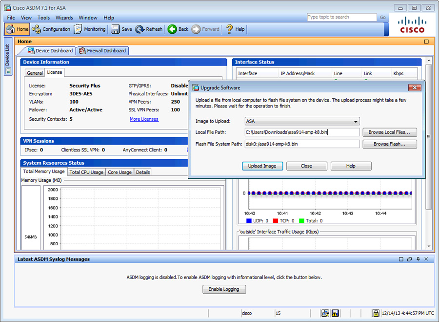
The security appliance assigns a message ID to each event it generates. As of Cisco ASA Software version 9.1(4), these message IDs range from 101001 to 768001 and contain a brief description of the event. The security appliance also associates each message ID to a severity level ranging from 0 to 7. The lower the severity level number is, the more critical the message is. Table 5-2 lists the severity levels, along with the associated keyword and a brief description.
Each severity level not only displays the events for that level but also shows the messages from the lower severity levels. For example, if logging is enabled for debugging (level 7), the security appliance also logs levels 0 through 6 events.
Note
For a complete list of all the severity messages, please consult the Error and System Messages guide located at http://www.cisco.com/go/asa under “Troubleshoot and Alerts.”
The next subsection discusses how to enable system logging (syslog) on the security appliance to record relevant events.
Enabling Logging
To enable logging of system events through ASDM, go to Configuration > Device Management > Logging > Logging Setup and check the Enable Logging check box. This option enables the security appliance to send logs to all the terminals and devices set up to receive the syslog messages.
The security appliance does not send debug messages as logs, such as debug icmp trace, to a syslog server unless you explicitly turn it on by checking the Send Debug Messages As Syslogs check box. For UDP-based syslogs, the security appliance allows logging of messages in the Cisco EMBLEM format. Many Cisco devices, including the Cisco IOS routers and Cisco Prime management server, use this format for syslogging. Figure 5-4 illustrates that syslogging is globally enabled, with debugs being sent as syslogs to an external server in the EMBLEM format.

Example 5-24 shows the equivalent configuration in the CLI format.
Chicago# configure terminal
Chicago(config)# logging enable
Chicago(config)# logging debug-trace
Chicago(config)# logging emblem
After the logging is enabled, ensure that the messages are timestamped before they are sent. This is extremely important because in case of a security incident, you want to use the logs generated by the security appliance to back trace. Navigate to Configuration > Device Management > Logging > Syslog Setup and choose the Include Timestamp in Syslog option. If you prefer to use the CLI, use the logging timestamp command, as shown in Example 5-25.
Example 5-25 Enabling Syslog Timestamps
Chicago(config)# logging timestamp
Defining Event List
The security appliance’s robust operating system enables you to define and choose the events and messages to be sent to specific syslog destinations. For example, you can choose to send all the VPN-related log messages to the local buffer, whereas all the other events can be sent to an external syslog server. You do so by defining a logging list under Configuration > Device Management > Logging > Event Lists > Add. ASDM prompts you to specify an “Event List” name, which can be used to specify the level of messages the security appliance should be logging. You can add events to this list based on either the Event Class or Message ID. In the Event Class option, you can classify messages using the predefined event classes to log specific processes and then assign appropriate severity to them. Table 5-3 lists the available classes and provides a brief explanation of each.

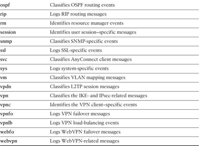
In Figure 5-5, a logging list called IPSec_Critical is set up to group all the vpn (IKE and IPsec) messages. The selected severity level is critical, which also includes level 0 and level 1 events.

Example 5-26 shows the equivalent configuration of Figure 5-5.
Example 5-26 Setting Up a Logging List
Chicago# configure terminal
Chicago(config)# logging list IPSec_Critical level Critical class vpn
Logging Types
Cisco ASA supports the following types of logging capabilities:
![]() External syslog server logging
External syslog server logging
The followings sections describe each logging type in detail.
Console Logging
Console logging enables the security appliance to send syslog messages to the console serial port. This method is useful for viewing specific live events during troubleshooting.
Caution
Enable console logging with caution; the serial port is only 9600 bits per second, and the syslog messages can easily overwhelm the port.
If the port is already overwhelmed, access the security appliance from an alternate method, such as SSH or Telnet, and lower the console-logging severity.
Terminal Logging
Terminal logging sends syslog messages to a remote terminal monitor such as a Telnet or SSH session. This method is also useful for viewing live events during troubleshooting. It is recommended that you define an event class for terminal logging so that your session does not get overwhelmed with the logs.
ASDM Logging
You can enable the security appliance to send logs to Cisco ASDM. This feature is extremely beneficial if you use ASDM as the configuration and monitoring platform. You can specify the number of messages that can exist in the ASDM buffer. By default, ASDM shows 100 messages in the ASDM logging window. You can use the logging asdm-buffer-size command to increase this buffer to store up to 512 messages.
Email Logging
The security appliance supports sending log messages directly to individual email addresses. This feature is extremely useful if you are interested in getting immediate notification when the security appliance generates a specific log message. When an interesting event occurs, the security appliance contacts the specified email server and sends an email message to the email recipient from a preconfigured email account.
Caution
Using email-based logging with a logging level of notifications or debugging may easily overwhelm an email server or the Cisco ASA.
Syslog Server Logging
Cisco ASA supports sending the event logs to one or multiple external syslog servers. Messages can be stored for use in anomaly detection or event correlation. The security appliance allows the use of both TCP and UDP protocols to communicate with a syslog server. You must define an external server to send the logs to it, as discussed later in the “Defining a Syslog Server” section.
SNMP Trap Logging
Cisco ASA also supports sending the event logs to one or multiple external SNMP servers. Messages are sent as SNMP traps for anomaly detection or event correlation. This is discussed in detail later in the chapter in the “Simple Network Management Protocol (SNMP)” section.
Buffered Logging
The security appliance allocates 4096 bytes of memory to store log messages in its buffer. This is the preferred method to troubleshoot an issue because it does not overwhelm the console or the terminal ports. If you are troubleshooting an issue that needs to store more messages than it can store, you can increase the buffer size up to 1,048,576 bytes.
Note
The allocated memory is a circular buffer; consequently, the security appliance does not run out of memory as the older events get overwritten by newer events.
In Figure 5-6, the logging level for the syslog servers is being set to debugging in the Edit Logging Filters dialog box. The figure also illustrates that the logging level for SNMP trap logging is an event list called FailoverCommunication, internal buffered logging is set to debugging, email logging is set to the FailoverCommunication event list, console logging is disabled, Telnet and SSH sessions logging is set to the IPSec_Critical event list, and ASDM logging is set to the Informational level. The email and syslog server parameters are discussed later in this chapter.
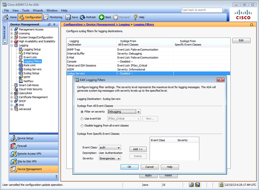
Example 5-27 shows the equivalent configuration of Figure 5-6.
Example 5-27 Setting Up a Logging List for Multiple Destinations
Chicago# configure terminal
Chicago(config)# logging list IPSec_Critical level critical class vpn
Chicago(config)# logging list FailoverCommunication message 105005
Chicago(config)# logging monitor IPSec_Critical
Chicago(config)# logging buffered debugging
Chicago(config)# logging trap debugging
Chicago(config)# logging history FailoverCommunication
Chicago(config)# logging asdm informational
Chicago(config)# logging mail FailoverCommunication
You can view the buffered logs by using the show logging command, as demonstrated in Example 5-28. This shows all different types of logging supported on the security appliance and indicates whether they are enabled or disabled. Additionally, it provides the number of messages logged on each of the configured logging types with the logging severity. Each syslog message starts with %ASA, to indicate that a Cisco security appliance generated the message, followed by the logging level, the unique message ID, and then a brief string to describe the log message.
Example 5-28 Output of show logging
Chicago# show logging
Syslog logging: enabled
Facility: 20
Timestamp logging: disabled
Standby logging: disabled
Debug-trace logging: enabled
Console logging: disabled
Monitor logging: list IPSec_Critical, 0 messages logged
Buffer logging: level debugging, 562 messages logged
Trap logging: level debugging, facility 20, 554 messages logged
Permit-hostdown logging: disabled
History logging: list FailoverCommunication, 0 messages logged
Device ID: disabled
Mail logging: list FailoverCommunication, 0 messages logged
ASDM logging: level informational, 177 messages logged
<167>:%ASA-session-7-710005: UDP request discarded from
172.18.82.20/17500 to outside:255.255.255.255/17500
<167>:%ASA-session-7-710005: UDP request discarded from
172.18.82.20/17500 to management:255.255.255.255/17500
<167>:%ASA-session-7-710005: UDP request discarded from
172.18.82.20/17500 to outside:255.255.255.255/17500
! Output omitted for brevity
Defining a Syslog Server
You must define an external UDP- or TCP-based syslog server before the Cisco ASA can send logs to it. To define a syslog server, navigate to Configuration > Device Management > Logging > Syslog Servers > Add. ASDM prompts you to specify an interface where the syslog server resides, the IP address of the server, a selection of UDP or TCP ports and the respective port numbers, and whether you want to send the log in the Cisco EMBLEM format to UDP-based syslog servers.
For TCP-based syslog servers, the security appliance
![]() Enables you to create a secure TLS connection so that the messages can be encrypted.
Enables you to create a secure TLS connection so that the messages can be encrypted.
![]() Drops all new connections if the session to the syslog server cannot be established.
Drops all new connections if the session to the syslog server cannot be established.
To enable secure communication between the security appliance and the TCP-based syslog server, check the Enable Secure Syslog Using SSL/TLS (TCP Only) check box. To allow new connections to be established if the TCP-based syslog server is down, check the Allow User Traffic to Pass When TCP Syslog Server Is Down check box at the bottom of the Syslog Servers window.
In Figure 5-7, two syslog servers to which log messages are to be sent are defined. The first server collects the logs, using UDP and in the Cisco EMBLEM format, and the other server uses TCP port 1470 to accept the syslog messages. The security appliance sends all logging level 7 and below messages to these servers. The security appliance is configured to establish secure connection with the TCP-based syslog server. If the syslog server is not available, the security appliance continues to establish new connections.
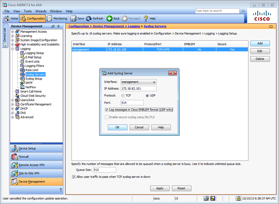
Example 5-29 shows the equivalent configuration of Figure 5-7.
Example 5-29 Setting Up Syslog Servers
Chicago# configure terminal
Chicago(config)# logging host management 172.18.82.100 6/1470 secure
Chicago(config)# logging host management 172.18.82.101 format emblem
Chicago(config)# logging trap debugging
Chicago(config)# logging permit-hostdown
Defining an Email Server
The security appliance enables you to send sensitive log messages via an email. This is extremely useful if you are monitoring a specific event or a group of events and want to get alerted right away when it occurs. To define a new SMTP server, navigate to Configuration > Device Management > Logging > SMTP and specify the IP address of the primary SMTP server and, optionally, the secondary SMTP server. Additionally, you must specify the source and destination email addresses. Define them by choosing Configuration > Device Management > Logging > E-Mail Setup. The source address is used to generate the log messages, whereas the destination email address is where the messages are sent.
In Example 5-30, a logging list called FailoverCommunication is set up with a message ID of 105005 to classify the failover communication issues. This logging list is linked to send email messages from [email protected] to [email protected], using 172.18.82.50 as the primary email server and 172.18.82.51 as the secondary email server.
Example 5-30 Configuration of Email Logging
Chicago(config)# logging list FailoverCommunication message 105005
Chicago(config)# logging mail FailoverCommunication
Chicago(config)# logging from-address [email protected]
Chicago(config)# logging recipient-address [email protected] level errors
Chicago(config)# smtp-server 172.18.82.50 172.18.82.51
Storing Logs Internally and Externally
The Cisco ASA enables you to save the buffered log messages as files to the local flash or to an FTP server for future analysis. The security appliance supports two methods to save buffered logs:
Flash Logging
Using the flash logging method, you can save the log messages located in the buffer space to the local flash (disk0: or disk1:). The security appliance creates a file in the / syslog directory of flash, using the default name of LOG-YYYY-MM-DD-HHMMSS.TXT, where YYYY stands for year, the first MM for month, DD for days, HH for hours, the second MM for minutes, and SS for seconds. Navigate to Configuration > Device Management > Logging > Logging Setup and check the Save Buffer To Flash check box. If you click the Configure Flash Usage button, you can specify the following options:
![]() Maximum Flash to Be Used by Logging: The maximum space the security appliance can use to store the buffered logs in flash
Maximum Flash to Be Used by Logging: The maximum space the security appliance can use to store the buffered logs in flash
![]() Minimum Free Space to Be Preserved: The minimum space in kilobytes that the security appliance should maintain to ensure that there is room left in flash for other administrative tasks
Minimum Free Space to Be Preserved: The minimum space in kilobytes that the security appliance should maintain to ensure that there is room left in flash for other administrative tasks
Note
The Cisco ASA uses the local clock settings to add the timestamp. Consult the “Setting Up the System Clock” section in Chapter 4.
It is important to understand that excessive writing to flash may shorten the lifespan of the compact flash card. Therefore, this option should not be used for high rates of syslogs.
Example 5-31 shows that the security appliance is allocating 2 MB of space to save logs in flash and the minimum free space in flash should be 4 MB.
Example 5-31 Automatic Saving of Logs in Flash
Chicago# configure terminal
Chicago(config)# logging flash-bufferwrap
Chicago(config)# logging flash-maximum-allocation 2000
Chicago(config)# logging flash-minimum-free 4000
Tip
The Cisco ASA also enables you to manually save the buffered logs to the local flash if you issue the logging savelog command. Check the flash directory by using the dir /recursive command. The /recursive option shows the complete file structure of the flash by displaying all files even if they are located in subdirectories.
FTP Logging
The security appliance can transfer the buffer logs to an FTP server to conserve disk space. You enable this by navigating to Configuration > Device Management > Logging > Logging Setup and checking the Save Buffer To FTP Server check box. You must click the Configure FTP Settings button and then check the Enable FTP Client check box and specify the IP address, username, and password.
In Example 5-32, an appliance is set up to send log files to an FTP server, located at 172.18.82.150. The username to log in to the FTP server is cisco with a password of C1$c0123. The logs are stored in the root directory (.) of the FTP server for that user.
Example 5-32 Automatic Saving of Logs in the FTP Server
Chicago# configure terminal
Chicago(config)# logging ftp-bufferwrap
Chicago(config)# logging ftp-server 172.18.82.150 . cisco C1$c0123
Syslog Message ID Tuning
The security appliance sends all log messages to the logging devices, internal and external, based on the severity level. However, if you are not interested in logging a particular message, suppress it by navigating to Configuration > Device Management > Logging > Syslog Setup, selecting the message ID, clicking Edit, and checking the Disable Messages check box. You can also achieve the same result with the CLI by issuing the no logging message command followed by the message ID number, as shown in Example 5-33, where message ID 103001 is disabled.
Example 5-33 Disabling a Message ID
Chicago# configure terminal
Chicago(config)# no logging message 103001
Even though the debug-level syslogs provide extensive information about the traffic and device health, many enterprises do not want to enable syslogs at that level. They choose to enable logging at the information or notification level and then move the appropriate debug-level message to a lower level. You can change a message’s logging level by navigating to Configuration > Device Management > Logging > Syslog Setup, selecting the message ID, clicking Edit, and selecting the appropriate level under Logging Level.
NetFlow Secure Event Logging (NSEL)
Cisco ASA supports using the NetFlow architecture to send syslogs, if you are using version 8.2(1) or higher. If you are using Cisco ASA 5580s, you can also enable this feature in the 8.1(1) version of the software. Sending logs via syslog is considered inefficient because
![]() Syslog sends logs in the ASCII text format, which produces logs that are verbose and lengthy.
Syslog sends logs in the ASCII text format, which produces logs that are verbose and lengthy.
![]() Syslog generates a single UDP packet for each log message, which results in a large number of small packets.
Syslog generates a single UDP packet for each log message, which results in a large number of small packets.
![]() Generating lots of text-based syslogs adds considerable load on the security appliance.
Generating lots of text-based syslogs adds considerable load on the security appliance.
Using NetFlow as a means to send syslogs can greatly enhance performance. The security appliance generates log information in binary, which can be parsed easily, and sends multiple records in a single flow packet.
Note
You must have a NetFlow collector in your network that can parse the flow of information the security appliance sends. CS-MARS running version 6.0 can read and parse NetFlow version 9 information. To learn more about NetFlow version 9, consult RFC 3954.
Cisco ASA uses NetFlow version 9, which leverages the template-based approach as a flow export mechanism. The NetFlow template defines the structure of the NetFlow record being exported. The NetFlow implementation exports records when a significant event in the life of a flow, such as creation and teardown, occurs. In Cisco ASA versions 8.4(5) and 9.1(2) or later, periodic flow updates are also sent to provide information about flows prior to flow teardown. The security appliance also exports information about flows that are allowed or denied by access control lists (ACL). ACLs are discussed in Chapter 8, “Controlling Network Access: The Traditional Way.”
You cannot display the NetFlow packets on a terminal session, unlike what you can do with a Cisco IOS router, where you can view the NetFlow data via the CLI. Additionally, the security appliance exports the flow information periodically to a collector. This is also different from the typical NetFlow version 9, such as on a Cisco IOS router, where the flows are exported in a single packet when a number of flows are collected.
When you are exporting logs via NetFlow, you do not want to send the same logs via syslog, to avoid duplication of packets. The security appliance allows you to disable all syslogs messages that generate the same information as NetFlow. This way, you do not have to manually disable individual syslogs in the Cisco ASA configuration. The security appliance disables 106015, 106023, 106100, 302013, 302014, 302015, 302016, 302017, 302018, 302020, 302021, 313001, 313008, and 710003 syslog messages.
The configuration of NSEL can be broken into two steps:
1. Define a NetFlow collector.
2. Define a NetFlow export policy.
Step 1: Define a NetFlow Collector
Using ASDM, define a NetFlow collector by navigating to Configuration > Device Management > Logging > NetFlow and clicking Add in the Collectors section. Specify the IP address, the UDP port that your collector uses for NetFlow packets, and the interface where the collector resides.
You can, optionally, configure a delay in sending the flow creation event. This is useful if you have a large number of created connections, so that the appliance can package them up into fewer export packets. If the flow is torn down before the configured delay, only the flow teardown event is dispatched and the flow creation event is not sent. You configure this by checking the Delay Transmission of Flow Creation Events for Short-Lived Flows check box.
The security appliance sends the template record to your NetFlow collector, by default, every 30 minutes. You can change the frequency when the template record is sent, in minutes, in the Template Timeout Rate option box. The default timeout value of 30 minutes works in most cases.
Figure 5-8 illustrates that a new NetFlow collector is being added. It is located toward the management interface at 172.18.82.81 and listens on UDP port 2055. The Disable Redundant Syslog Messages check box is also enabled, to avoid duplication of syslog messages.
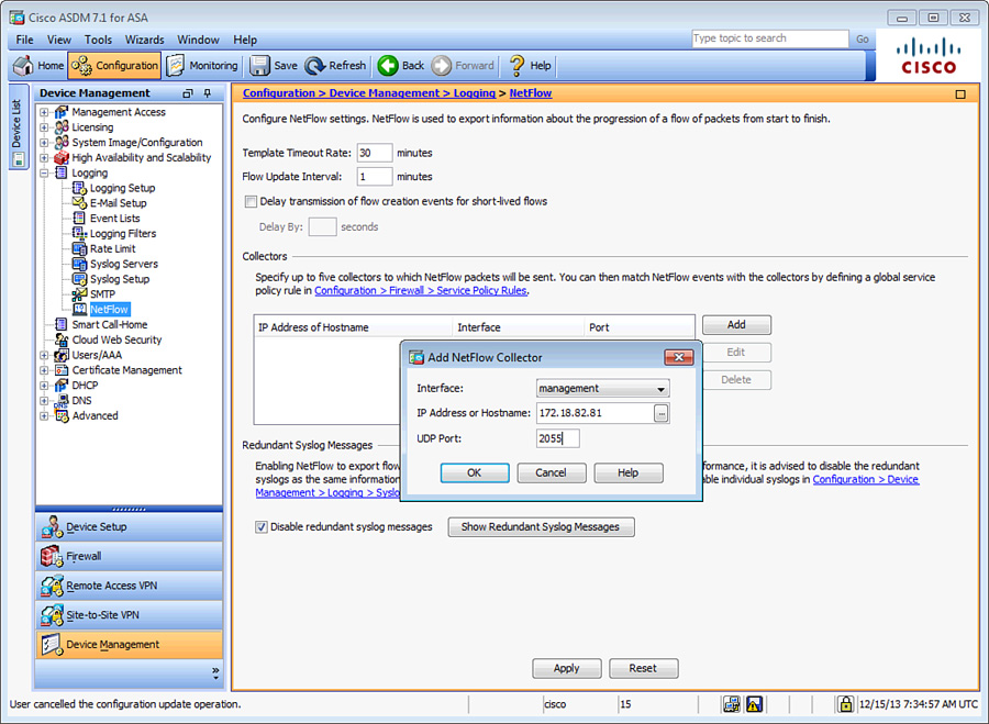
Example 5-34 shows the equivalent configuration of Figure 5-8.
Example 5-34 Configuring NetFlow via CLI
Chicago# configure terminal
Chicago(config)# no logging message 106015
Chicago(config)# no logging message 106023
Chicago(config)# no logging message 106100
Chicago(config)# no logging message 302013
Chicago(config)# no logging message 302014
Chicago(config)# no logging message 302015
Chicago(config)# no logging message 302016
Chicago(config)# no logging message 302017
Chicago(config)# no logging message 302018
Chicago(config)# no logging message 302020
Chicago(config)# no logging message 302021
Chicago(config)# no logging message 313001
Chicago(config)# no logging message 313008
Chicago(config)# no logging message 710003
Chicago(config)# flow-export destination management 172.18.82.81 2055
Tip
You can now use the logging flow-export-syslogs disable command to disable all these syslogs without having to list each individually.
Step 2: Define a NetFlow Export Policy
The security appliance does not send NetFlow packets to an external collector until you classify the traffic type it should be monitoring to generate the NetFlow events. For example, if you want it to monitor all traffic for NetFlow exports, specify a global policy that analyzes all traffic. NetFlow export policy is constructed via the Modular Policy Framework (MPF), discussed in Chapter 13, “Application Inspection,” and Chapter 25, “Quality of Service.” Follow these steps to successfully configure an export policy:
1. Navigate to Configuration > Firewall > Service Policy Rules, select the inspection_default policy, and then choose Add > Insert After. ASDM launches an Add Service Policy Rule Wizard. Click the Global – Applies to All Interfaces radio button. Click Next.
2. Under Create a new traffic class, specify a traffic class name of NetFlow. Check the Any Traffic check box as the Traffic Match Criteria and click Next.
3. Under Rule Actions, click the NetFlow tab and click Add. A new window opens where you can specify Flow Event Type. Select All and check the Send check box next to the collector’s IP address. This collector was defined under the preceding “Step 1: Defining a NetFlow Collector” section. Click OK and then click Finish to complete defining a NetFlow export policy.
If you prefer to use the CLI, you can define an identical policy as shown in Example 5-35.
Example 5-35 Defining an NetFlow Export Policy
Chicago(config)# class-map NetFlow
Chicago(config-cmap)# match any
Chicago(config-cmap)# policy-map global_policy
Chicago(config-pmap)# class NetFlow
Chicago(config-pmap-c)# flow-export event-type all destination 172.18.82.81
Cisco ASA also enables you to monitor the status of the NetFlow exports if you use the show flow-export counters command as shown in Example 5-36. It displays the number of export packets sent and statistics about any potential export issues.
Example 5-36 Monitoring NetFlow Exports
Chicago# show flow-export counters
destination: outside 172.18.82.81 2055
Statistics:
packets sent 100
Errors:
block allocation failure 0
invalid interface 0
template send failure 0
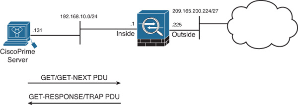
Simple Network Management Protocol (SNMP)
SNMP is an application layer protocol that was developed to monitor the health of network devices. It has become a de facto standard because of its simple protocol design. A successful SNMP implementation requires a management station, also known as the manager, and at least one agent, such as the Cisco ASA. The network management station, such as Cisco Prime LAN Management Solution (LMS), monitors the agents by collecting the device and network information and presenting it in a GUI. The agents, on the other hand, respond to the manager’s request for information. If an important event occurs, the agents can also initiate a connection to the manager to send the message.
The SNMP implementation uses the following five message types, known as protocol data units (PDU), for the communication between the management station and the agent:
![]() GET
GET
![]() GET-NEXT
GET-NEXT
![]() GET-RESPONSE
GET-RESPONSE
![]() SET
SET
![]() TRAP
TRAP
The network manager uses the Management Information Base (MIB) to initiate the GET and GET-NEXT messages and request specific information. The agent replies with a GET-RESPONSE, which provides the requested information, if available. In a case where the requested information is not available, the agent sends an error detailing why the request cannot be processed.
The network manager uses the SET message type to change or add values in the configuration rather than retrieve the information. The agent replies with a GET-RESPONSE message to indicate whether the change was successful. The TRAP messages are agent-initiated to inform the network manager about an event, such as a link failure, so that an immediate action can be taken. Figure 5-9 illustrates the PDU communication between a security appliance, as an agent, and a Cisco Prime server, as a management server.
Note
The security appliance does not allow SET PDUs, for device-security reasons. Consequently, you cannot use SNMP to modify the configuration of the security appliance.
Configuring SNMP
The security appliance must be configured before a network management server can initiate a connection. Configure SNMP on a security appliance through ASDM by navigating to Configuration > Device Management > Management Access > SNMP and following these steps:
1. Configure a global community string. A community string acts as a password when the management server tries to connect to the security appliance to get information. It is used to validate the communication messages between the devices. In ASDM, specify a global community string in the Community String (Default) field. It is masked and shown as asterisks. If you prefer to use the CLI, set a global community string by using the snmp-server community command.
2. Set device information.
Specify the location of the security appliance so that the SNMP server knows where the device is physically located. The security appliance enables you to set up contact information for an individual who is responsible for it. In ASDM, specify the device information, such as the Contact and ASA Location options. If you prefer to use the CLI, use the snmp-server location and snmp-server contact commands.
3. Modify SNMP polling ports.
The Cisco ASA can be configured to listen on a non-default port for SNMP polls. To use a port other than UDP 161, specify it in the Listening Port field. If you are using the CLI, use the snmp-server listen-port command, followed by a port number.
4. Define an SNMP server.
You must specify an SNMP management server before the ASA can listen for polls or send SNMP traps. To define a new SNMP server, click Add under SNMP Host Access List and specify the following information:
![]() Interface Name: The name of the interface where the SNMP server resides. In most cases, it is the inside or the management interface. If you select an interface other than the inside interface, ASDM generates a warning that you should consider about using an inside interface for security reasons. However, using a management interface is as secure if you have a dedicated management network.
Interface Name: The name of the interface where the SNMP server resides. In most cases, it is the inside or the management interface. If you select an interface other than the inside interface, ASDM generates a warning that you should consider about using an inside interface for security reasons. However, using a management interface is as secure if you have a dedicated management network.
![]() IP Address: The actual IP address of the SNMP server. The IP address must reside toward the selected interface.
IP Address: The actual IP address of the SNMP server. The IP address must reside toward the selected interface.
![]() UDP Port: The security appliance uses UDP port 162 when it needs to send SNMP traps to the management server. If the SNMP server listens on a different port, you can change the UDP port on the security appliance by specifying a port in the UDP Port field.
UDP Port: The security appliance uses UDP port 162 when it needs to send SNMP traps to the management server. If the SNMP server listens on a different port, you can change the UDP port on the security appliance by specifying a port in the UDP Port field.
![]() SNMP Version: The security appliance supports SNMP versions 1, 2c, and 3. Version 2c overcomes the deficiencies and problems associated with version 1. It uses the administrative framework of version 1 but enhances protocol operations by increasing security capabilities. SNMPv3 adds many security and remote configuration enhancements such as message integrity (to ensure that a packet has not been tampered with in transit), authentication (to verify that the message is from a valid source), and encryption (to prevent snooping by an unauthorized source). If you select SNMP version 3, you must define a username. If you select SNMP version 1 or 2c, ASA enables you to specify a host-specific SNMP community string.
SNMP Version: The security appliance supports SNMP versions 1, 2c, and 3. Version 2c overcomes the deficiencies and problems associated with version 1. It uses the administrative framework of version 1 but enhances protocol operations by increasing security capabilities. SNMPv3 adds many security and remote configuration enhancements such as message integrity (to ensure that a packet has not been tampered with in transit), authentication (to verify that the message is from a valid source), and encryption (to prevent snooping by an unauthorized source). If you select SNMP version 3, you must define a username. If you select SNMP version 1 or 2c, ASA enables you to specify a host-specific SNMP community string.
![]() Server Poll/Trap Specification: The security appliance allows an SNMP server to poll information from the security appliance. It also sends event traps when unusual incidents occur. You can optionally restrict the security appliance to allow either SNMP polls only or traps only. In most implementations, an SNMP server is designed to poll as well as receive traps from the network devices.
Server Poll/Trap Specification: The security appliance allows an SNMP server to poll information from the security appliance. It also sends event traps when unusual incidents occur. You can optionally restrict the security appliance to allow either SNMP polls only or traps only. In most implementations, an SNMP server is designed to poll as well as receive traps from the network devices.
5. Configure SNMP traps.
The security appliance sends limited SNMP traps by default; however, you can configure it to send all supported traps or a superset of all traps. Do so by clicking the Configure Traps button (to the right of the Listening Port field) and selecting the trap types as shown in Table 5-4.
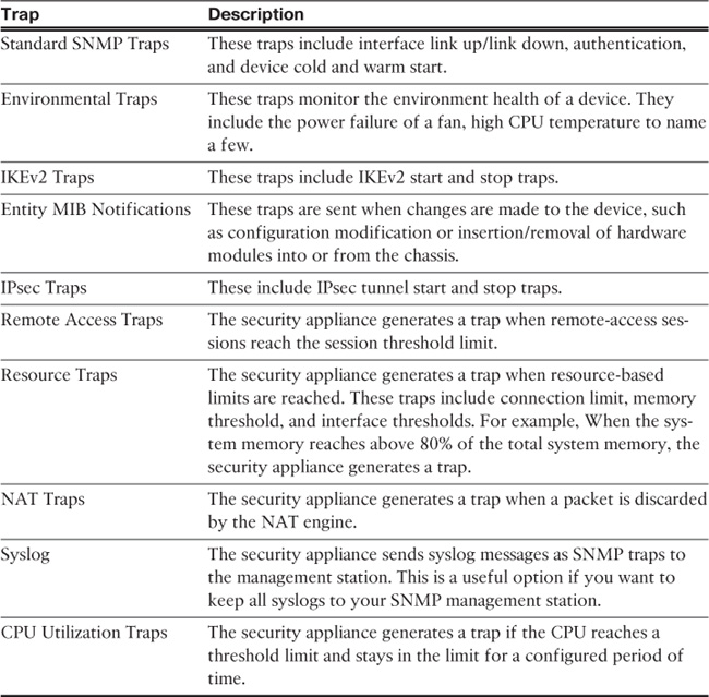
Note
To set up traps for syslog messages, you must determine the level of severity at which syslog messages need to be forwarded to the management server. This was discussed earlier in the “Logging Types” section.
In Figure 5-10, a new SNMP server is being added. The IP address of the server is 172.18.82.80 and it is located toward the management interface. The server is configured to use SNMP version 3, which requires you to configure a username. The configured user name is cisco.

Example 5-37 shows the equivalent CLI configuration of Figure 5-10.
Example 5-37 Setting Up SNMP Version 3
Chicago# configure terminal
Chicago(config)# snmp-server community s3c3r3m3$nmp
Chicago(config)# snmp-server location Chicago
Chicago(config)# snmp-server contact Jack Franklin
Chicago(config)# snmp-server host management 172.18.82.80 community s3c3r3m3$nmp
version 3 cisco
Chicago(config)# snmp-server group Authentication&Encryption v3 priv
Chicago(config)# snmp-server user cisco Authentication&Encryption v3
auth MD5 0:1:2:3:4:5:6:7 priv AES 256 cisco123
Chicago(config)# logging history debugging
Chicago(config)# snmp-server enable traps syslog
SNMP Monitoring
The show snmp-server statistics command is useful for checking the statistics of the SNMP engine. It displays not only the total SNMP packets received and transmitted but also any bad or illegal packets handled by the security appliance. Example 5-38 displays the output of this command, where the security appliance received 12 GET requests and replied to all of them as GET-RESPONSE.
Example 5-38 Output of show snmp-server statistics
Chicago# show snmp-server statistics
12 SNMP packets input
0 Bad SNMP version errors
0 Unknown community name
0 Illegal operation for community name supplied
0 Encoding errors
36 Number of requested variables
0 Number of altered variables
12 Get-request PDUs
0 Get-next PDUs
0 Get-bulk PDUs
0 Set-request PDUs (Not supported)
12 SNMP packets output
0 Too big errors (Maximum packet size 512)
0 No such name errors
0 Bad values errors
0 General errors
12 Get-response PDUs
0 SNMP trap PDUs
Device Monitoring and Troubleshooting
Cisco ASA is loaded with a number of show and debug commands to monitor the health of the device and troubleshoot any network- or device-level issues.
CPU and Memory Monitoring
The show cpu usage command indicates current CPU utilization. It displays an approximation of load over 5, 60, and 300 seconds. You can also use the show cpu usage detailed command if you want to see the CPU utilization breakdown for each core. Example 5-39 shows that the 5-second utilization is 2 percent, whereas the 1-minute and 5-minute utilizations are 1 percent.
Example 5-39 Output of show cpu usage
Chicago(config)# show cpu usage
CPU utilization for 5 seconds = 2%; 1 minute: 1%; 5 minutes: 1%
The security appliance displays memory usage through the show memory command. It shows a summary of the available and allocated memory in bytes and as a percentage. In Example 5-40, the free memory on the security appliance is 1,574,582,128 bytes (~1575 MB), and the allocated or used memory is 572,901,520 bytes (~573 MB). The total memory on the security appliance is 2048 MB.
Example 5-40 Output of show memory
Chicago# show memory
Free memory: 1574582128 bytes (73%)
Used memory: 572901520 bytes (27%)
------------- ------------------
Total memory: 2147483648 bytes (100%)
Note
Using the show memory detail command output with show memory binsize enables you to check the number of bytes allocated to a given size memory chunk. These commands should be used under a TAC engineer’s supervision if advanced memory troubleshooting needs to be done.
The security appliance displays the system buffer utilization if the show block command is executed. When the security appliance boots up, the operating system carves out memory to create the maximum number of blocks for different block sizes. The maximum number of blocks does not change, except for the 256- and 1550-size blocks. For these blocks, the security appliance can dynamically create more blocks if necessary. The security appliance allocates a block from the pool when it needs to use it, and returns it when it is done using it.
There are 12 different sizes of buffer blocks, and each buffer type is responsible for handling specific packets. Table 5-5 shows the buffer block sizes and provides a brief description on where they are used.
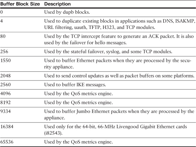
When you run the show block command, the security appliance displays the following counters:
![]() MAX: Indicates the maximum number of blocks available for a specific block size.
MAX: Indicates the maximum number of blocks available for a specific block size.
![]() LOW: Indicates the lowest numbers of blocks available at one point since the last reboot or the last time the counters were cleared by the clear block command. A low count of 0 indicates that the security appliance had run out of buffer space for a particular block at some point since the last reboot or the last time the counters were cleared.
LOW: Indicates the lowest numbers of blocks available at one point since the last reboot or the last time the counters were cleared by the clear block command. A low count of 0 indicates that the security appliance had run out of buffer space for a particular block at some point since the last reboot or the last time the counters were cleared.
![]() CNT: Displays the current count of available blocks for each buffer size.
CNT: Displays the current count of available blocks for each buffer size.
In Example 5-41, the security appliance has allocated 248 blocks for the 4-byte block size, and it is currently using one block. The LOW counter is set to 247 because the security appliance had allocated only one block of it since the last reboot.
Example 5-41 Output of show block
Chicago# show block
SIZE MAX LOW CNT
0 950 944 944
4 248 247 247
80 1400 1394 1400
256 5048 5028 5029
1550 8427 8338 8422
2048 1600 1600 1600
2560 1476 1476 1476
4096 100 100 100
8192 100 100 100
9344 100 100 100
16384 126 126 126
65536 16 16 16
Using ASDM, monitor the health of a security appliance by navigating to Monitoring > Properties > System Resources Graphs and selecting a graph for Block use, CPU utilization, and memory use and availability.
Troubleshooting Device Issues
Cisco ASA provides a number of troubleshooting and diagnostic commands for troubleshooting traffic as well as device-related issues.
Troubleshooting Packet Issues
In any firewall deployment, administrators spend their time defining new policies and troubleshooting packet flow issues. The following sections discuss three scenarios to show how the security appliance assists in troubleshooting those issues.
Tracing Packet Flow
To learn which processes are being applied to a packet flow, employ the Cisco ASDM Packet Tracer feature. Using this feature, you can describe how a packet should be structured based on the IP protocol, source and destination IP addresses, and source and destination ports. The security appliance provides information when that packet goes through different processes such as the ACLs, routing, and address translation (NAT). Each process inspects the packet individually and decides whether it needs to allow or deny that packet.
Use this feature by choosing Tools > Packet Tracer and specifying the interface from which the packet should be coming, the IP protocol, and the source and destination IP addresses and ports Figure 5-11 illustrates the tracing of a TCP packet sourced toward the inside interface from 192.168.10.50 and destined to 209.165.200.229 on source port 1024 and destination port 80. Each process checks the packet and allows it, the end result is successful, and that packet is allowed to pass through the security appliance.
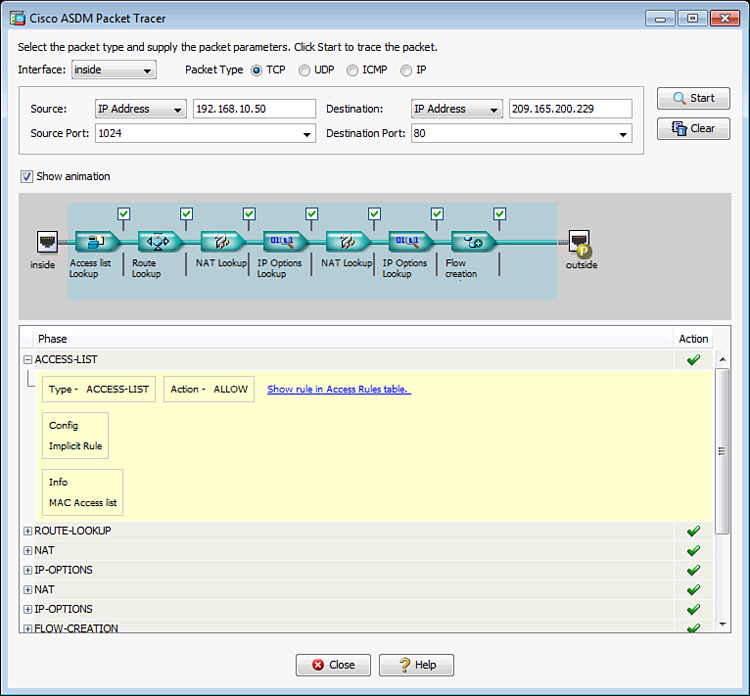
Example 5-42 shows the CLI equivalent of Figure 5-11.
Example 5-42 Tracing Packet Through the CLI
Chicago# packet-tracer input inside tcp 192.168.10.50 1024 209.165.200.229 80
Capturing Packets
One of the most robust features in the security appliance for troubleshooting traffic-related problems is the Packet Capture feature. When a packet capture is enabled, the security appliance sniffs interesting traffic and stores it in a buffer. This is important if you want to confirm that traffic from a particular host or network is arriving at or leaving from a specific interface. Use an ACL or the match keyword to identify the type of traffic and bind it to an interface by using the capture command. The captured packets can be viewed either locally on the security appliance or on an external device such as Wireshark if you export the information in the pcap format.
In Example 5-43, a capture list, named cap-inside, is being defined to match packets sourced from 209.165.202.130 and destined to 209.165.200.230. This capture is to the inside interface.
To view the captured packets, use the show capture command, followed by the name of the capture list. In Example 5-43, the security appliance captured 15 packets that matched the policy within the capture command. The highlighted entry shows that it is a TCP SYN (shown as “S” after the destination port) packet sourced from 209.165.202.130 with a source port of 11084 and it is destined for 209.165.200.230 on destination port 23. The TCP window size is 4128, and the Maximum Segment Size (MSS) is set to 536 bytes.
Chicago(config)# capture cap-inside interface inside match ip host 209.165.202.130
host 209.165.200.230
Chicago(config)# show capture cap-inside
15 packets captured
1: 02:12:47.142189 209.165.202.130.11084 > 209.165.200.230.23: S
433720059:433720059(0) win 4128 <mss 536>
2: 02:12:47.163489 209.165.202.130.11084 > 209.165.200.230.23: . ack 1033049551 win
4128
!Output omitted for brevity
15 packets shown
Tip
To see traffic in real time, use the real-time keyword in the capture. For example, the capture command in Example 5-43 can be defined for real-time traffic analysis as capture out-inside interface inside match ip host 209.165.202.130 host 209.165.200.230 real-time. Even though real-time capturing is extremely useful in troubleshooting traffic-related issues, the security appliance displays up to only 1000 packets in case of excessive traffic load.
When the capture command is enabled, the security appliance allocates memory immediately. The default memory allocation is 512 KB. The security appliance can overwrite content when the allocated memory is full by removing the oldest entry first if the circular-buffer option is used. Otherwise the security appliance stops saving packets once the buffer is full. The capture command may have an impact on the ASA’s CPU depending on device load and platform. While the impact is normally negligible, on a heavily loaded firewall, the additional load of the capture may cause performance issues. If you are concerned about potential impact after applying a capture, check the output of show cpu usage to verify CPU usage.
The output of the capture command can be exported into pcap format, which can be imported into a sniffing tool such as Wireshark or TCPDUMP for further analysis. To download the file in pcap format, use https://<IPAddressOfASA>/capture/<CaptureName>/ pcap in a browser. For example, to download the pcap file for the capture defined in Example 5-43, use https://172.18.82.75/capture/cap-inside/pcap.
In multiple-context mode, use https://<device-ip>/<context>/capture/<capname>/pcap/. Multiple-context mode is discussed in Chapter 14, “Virtualization.”
Monitoring Dropped Packets
The security appliance, being a firewall, drops packets if they do not adhere to an enterprise’s configured security policy. These drops could be related to the deny statements in the ACLs, illegitimate VPN packets, a malformed TCP segment, or a packet with invalid header information. In some cases, you will want to get the statistical information about the packets or connections dropped by the security appliance within its accelerated security path (ASP). Use the show asp drop command as shown in Example 5-44, which shows that over 57,000 packets were dropped because of the deny statement in the ACLs. Approximately 300 packets were dropped because the security appliance received a non-SYN packet as the first packet of a connection. This usually occurs when the client and server believe that a connection was open but the firewall has already closed that session. Finally, the security appliance dropped three packets when the interface was shut down.
Note
For a complete list of asp drop reasons, refer to the Cisco Security Appliance Command Reference for the Cisco ASA Software version you are using.
Example 5-44 Output of show asp drop
Chicago# show asp drop
Frame drop:
Flow is denied by configured rule (acl-drop) 57455
First TCP packet not SYN (tcp-not-syn) 295
Interface is down (interface-down) 3
Last clearing: Never
Note
The security appliance enables you to capture on a specific drop type or all asp drop types through the capture command, as follows:
Chicago# capture AspCapture type asp-drop ?
acl-drop Flow is denied by configured rule
all All packet drop reasons
bad-crypto Bad crypto return in packet
<output removed for brevity>
Troubleshooting CPU Issues
If you are monitoring your CPU utilization and it is constantly running high, activate the CPU profiling feature on the security appliance by using the cpu profile activate command. You can also allocate memory for storing a specific number of samples, which can vary from 1 to 100,000, with the default being 1000. The more memory you allocate to this process, the better the accuracy for CPU profiling. After CPU profiling is activated, use the show cpu profile dump command to view the output. Unfortunately, you have to send the output of this show command to a TAC engineer for analysis.
Summary
This chapter discussed the two important configurations, running and startup, in the security appliance. Telnet and SSH were explored as the remote-management protocols. This chapter also assisted in system maintenance features such as image upgrade and password recovery methods. The last section discussed the security appliance monitoring capabilities, such as system logging, SNMP, and a set of show commands to check the device’s status and health. To troubleshoot common issues related to memory and traffic, packet tracer and packet capture commands were also examined.