Chapter 2. Cisco ASA Product and Solution Overview
This chapter covers the following topics:
![]() All Cisco ASA 5500 and 5500-X Models
All Cisco ASA 5500 and 5500-X Models
![]() Cisco ASA Services Module
Cisco ASA Services Module
![]() Cisco ASA 1000V Cloud Firewall
Cisco ASA 1000V Cloud Firewall
![]() Cisco ASA CX
Cisco ASA CX
![]() Cisco ASA Advanced Inspection and Prevention (AIP) Modules
Cisco ASA Advanced Inspection and Prevention (AIP) Modules
![]() Deployment examples
Deployment examples
The Cisco ASA 5500 and ASA 5500-X Series Next-Generation Firewalls integrate firewall, IPS, and VPN capabilities, providing an all-in-one solution for your network. Incorporating all these solutions into Cisco ASA secures the network without the need for extra overlay equipment or network alterations. This is something that many Cisco customers and network professionals have requested in a security product.
This chapter provides an overview of the Cisco ASA 5500 Series Adaptive Security Appliance hardware and the Cisco ASA 1000V Cloud Firewall, including performance and technical specifications. It also offers an overview of the Advanced Inspection and Prevention Security Services Module (AIP-SSM), which is required for IPS features. Additionally, it introduces Cisco ASA Next-Generation Firewall Services (previously known as the Cisco ASA CX Context-Aware Security), designed to provide context-aware capabilities for granular control of applications, comprehensive user identification, and location-based control services. Cisco ASA Next-Generation Firewall Services adds new capabilities, including Cisco Application Visibility and Control (AVC), IPS, and Cisco Web Security Essentials (WSE), to the Cisco ASA 5500-X Series. Additionally, a centralized management application called Cisco Prime Security Manager allows security administrator to easily scale and manage these Next-Generation firewall services. This chapter also discusses the Cisco ASA 4-Port Gigabit Ethernet Security Services Module (SSM-4GE), which extends the number of physical interfaces in an appliance.
Cisco ASA Model Overview
There are several Cisco ASA 5500 and ASA 5500-X Series Next-Generation Firewall models. These include
![]() Cisco ASA 5505
Cisco ASA 5505
![]() Cisco ASA 5510
Cisco ASA 5510
![]() Cisco ASA 5512-X
Cisco ASA 5512-X
![]() Cisco ASA 5515-X
Cisco ASA 5515-X
![]() Cisco ASA 5520
Cisco ASA 5520
![]() Cisco ASA 5525-X
Cisco ASA 5525-X
![]() Cisco ASA 5540
Cisco ASA 5540
![]() Cisco ASA 5545-X
Cisco ASA 5545-X
![]() Cisco ASA 5550
Cisco ASA 5550
![]() Cisco ASA 5555-X
Cisco ASA 5555-X
![]() Cisco ASA 5585-X SSP-10
Cisco ASA 5585-X SSP-10
![]() Cisco ASA 5585-X SSP-20
Cisco ASA 5585-X SSP-20
![]() Cisco ASA 5585-X SSP-40
Cisco ASA 5585-X SSP-40
![]() Cisco ASA 5585-X SSP-60
Cisco ASA 5585-X SSP-60
![]() Cisco ASA Services Module
Cisco ASA Services Module
![]() Cisco ASA 1000V Cloud Firewall
Cisco ASA 1000V Cloud Firewall
Table 2-1 lists the Cisco ASA models and where or how they are typically used.

Cisco ASA 5505 Model
The Cisco ASA 5505 model is designed for small business, branch office, and telecommuting environments. Despite its small size, it provides firewall, SSL and IPsec VPN, and numerous networking services expected on a bigger appliance. Figure 2-1 shows the front view of the Cisco ASA 5505.
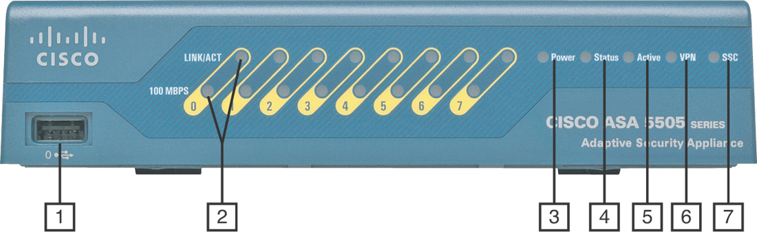
The front panel has the following components:
1. USB port: Reserved for future use.
2. Speed and Link Activity LEDs: The Cisco ASA 5505 has a speed indicator LED and a separate link activity indicator LED for each of its eight ports. When the speed indicator LED is not lit, it indicates that network traffic is flowing at 10 megabits per second (Mbps). When the speed indicator LED is green, it indicates that network traffic is flowing at 100 Mbps. When the link activity LED is solid green, it indicates that the physical network link has been established; when flashing, it indicates that there is network activity.
3. Power LED: Solid green indicates that the appliance is powered on.
4. Status LED: Flashing green indicates that the system is booting and power-up tests are running. Solid green indicates that the system tests passed and the system is operational. Amber solid indicates that the system tests failed.
5. Active: Green indicates that this Cisco ASA is active when configured for failover. If the Cisco ASA is configured as a standalone appliance this LED is green.
6. VPN: Solid green indicates that one or more VPN tunnels are active.
7. SSC LED: Solid green indicates that a Security Services Card (SSC) is present in the SSC slot.
The Cisco ASA 5505 features a flexible 8-port 10/100 Fast Ethernet switch, whose ports can be dynamically grouped to create up to 3 separate VLANs with trunking disabled and up to 20 VLANs with trunking enabled for home, business, and Internet traffic for improved network segmentation and security. The Cisco ASA 5505 provides two Power over Ethernet (PoE) ports, enabling simplified deployment of Cisco IP phones with zero-touch secure Voice over IP (VoIP) capabilities, and deployment of external wireless access points for extended network mobility. Figure 2-2 illustrates the back panel of the Cisco ASA 5505.

The rear panel has the following components:
1. Power connector.
2. SSC slot: Used for the Cisco ASA Advanced Inspection and Prevention Security Services Module 5 (AIP-SSC-5). This module is now end-of-life (EOL) and Cisco no longer sells it.
3. Serial console port: The RJ-45 console port enables you to physically connect to the appliance to access its command-line interface (CLI) for initial configuration.
4. Lock device: Used to physically lock the Cisco ASA.
5. Reset button: Reserved for future use.
6. Two USB version 2.0 ports: Reserved for future use.
7. Ethernet switch ports 0 through 5: 10/100 Fast Ethernet switch ports.
8. Ethernet switch ports 6 and 7: 10/100 Fast Ethernet switch ports with PoE.
You can install a Security Plus upgrade license, enabling the Cisco ASA 5505 to scale to support a higher connection capacity and a higher number of IPsec VPN users, add full DMZ support, and integrate into switched network environments through VLAN trunking support. Furthermore, this upgrade license maximizes business continuity by enabling support for redundant ISP connections and stateless Active/Standby high-availability services. This makes the Cisco ASA 5505 a great solution for small businesses and branch offices. Figure 2-3 illustrates how a Cisco ASA 5505 is deployed at a small branch office.
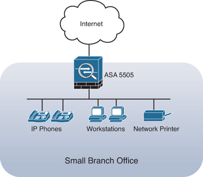
In the example illustrated in Figure 2-3, several workstations, a network printer, and IP phones are protected by the Cisco ASA 5505. The IP phones are connected to the Fast Ethernet switch ports 6 and 7 (which provide power to the phones).
Figure 2-4 shows how a Cisco ASA 5505 is deployed at a small business with two different protected network segments. The inside network (Vlan 10) has several workstations, the DMZ (Vlan 20) has two web servers, and the outside interface faces toward the Internet.

Note
Configuration information on how to control network access and create different interfaces with separate security levels is covered in Chapter 8, “Controlling Network Access: The Traditional Way.”
Figure 2-5 shows how a Cisco ASA 5505 can be used by telecommuters and home users to connect to a centralized location via VPN.

In Figure 2-5, telecommuters are protected by a Cisco ASA 5505 on each respective location. The Cisco ASA 5505s connect to the corporate headquarters via IPsec VPN tunnels.
Note
Configuration and troubleshooting of remote access VPN tunnels is covered in Chapter 20, “IPsec Remote-Access VPNs.”
Cisco ASA 5510 Model
The Cisco ASA 5510 model is designed to deliver advanced security services for small- and medium-sized businesses and enterprise branch offices. This model provides advanced firewall and VPN capabilities and has optional Anti-X (Cisco Adaptive Threat Defense) and IPS services that use the Cisco ASA Advanced Inspection and Prevention Security Services Module 10 (AIP-SSM-10).
Figure 2-6 shows a front view of the Cisco ASA 5510 model.

The front panel of the Cisco ASA 5510, 5520, 5540, and 5550 are the same with the exception of the model number (label).
The front panel has the following five LEDs:
1. Power: Solid green indicates that the appliance is powered on.
2. Status: Flashing green indicates that the system is booting and power-up tests are running. Solid green indicates that the system tests passed and the system is operational. Amber solid indicates that the system tests failed.
3. Active: Green indicates that this Cisco ASA is active when configured for failover. If the Cisco ASA is configured as a standalone appliance, the LED is green.
4. VPN: Solid green indicates that one or more VPN tunnels are active.
5. Flash: Flashing green indicates that the Flash memory card is being accessed.
The Cisco ASA 5510, 5512-X, 5515-X, 5520, 5525-X, 5540, 5545-X, 5550, and 5555-X offer a one-rack unit (1RU) design. Figure 2-7 shows a back view of the Cisco ASA 5510 model.
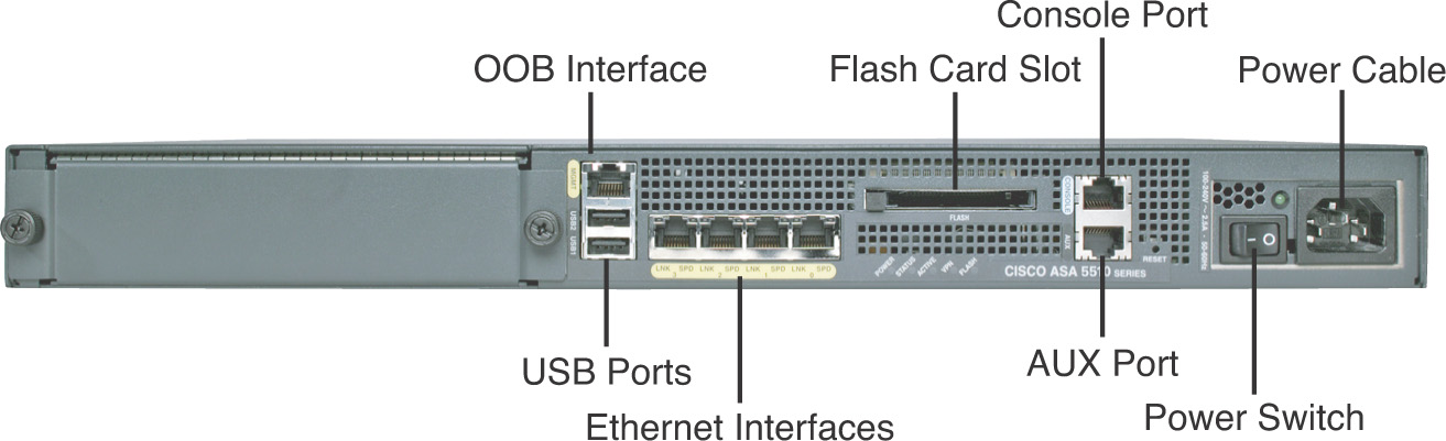
The Power, Status, Active, VPN, and Flash LEDs are also present on the back of the Cisco ASA 5510. The Cisco ASA 5510 includes five integrated 10/100 Fast Ethernet network interfaces. Three of these five Fast Ethernet ports are enabled by default (0 to 2). The fifth interface is reserved for out-of-band (OOB) management. Starting with Cisco ASA Software versions 7.2(2) and 8.0(3) respectively, restriction on the OOB port has been removed. Therefore, you can use all five Fast Ethernet interfaces for the through traffic and apply security services.
Note
Although the OOB Ethernet port restriction was removed beginning with versions 7.2(2) and 8.0(3), it is highly recommended that you use this port solely for OOB management.
Each Fast Ethernet port has an activity LED and a link LED:
![]() The activity LED shows that data is passing on the network to which the port is attached.
The activity LED shows that data is passing on the network to which the port is attached.
![]() The link LED shows that the port is operational.
The link LED shows that the port is operational.
The Cisco ASA 5510 Security Plus license enables Cisco ASA 5510 to provide VLAN support on switched networks (up to 100 VLANs). The Security Plus upgrade license also upgrades two of the interfaces to Gigabit Ethernet, allows up to five virtual firewalls, and provides a greater number of concurrent VPN connections for remote users and site-to-site connections.
The RJ-45 console port enables you to physically connect to the appliance to access its command-line interface (CLI) for initial configuration. The AUX (auxiliary) port enables you to connect an external modem for OOB management. The flash card slot enables you to use an external flash card to save system images and configuration files.
Two USB ports in the back of all Cisco ASA models are designed for future features. The Reset button is reserved for future use.
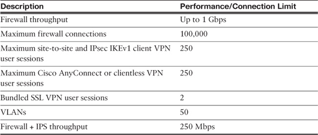
Table 2-2 lists the capabilities of the Cisco ASA 5510 appliance and its performance and connection limit numbers.

Note
Performance numbers vary depending on the packet size and other applications running on the appliance. For more detailed information, go to http://www.cisco.com/go/asa.
Cisco ASA 5512-X Model
The Cisco ASA 5512-X model is also designed for small and medium-sized businesses and enterprise branch offices. The Cisco ASA 5512-X, 5515-X, 5525-X, 5545-X, and 5555-X provide advanced firewall and VPN capabilities and IPS services that do not require a hardware module. With the addition of a solid-state drive (SSD), these appliances may also run Next-Generation Firewall Services alongside the traditional Cisco ASA firewall features.
Figure 2-8 shows a front view of the Cisco ASA 5512-X model.

The front and back views of the Cisco ASA 5512-X, 5515-X, and 5525-X have the same design. The Cisco ASA 5545-X and 5555-X front panels have two slots to allow an administrator to install two SSDs. The Cisco ASA 5545-X and 5555-X can be configured with dual power supplies. Figure 2-9 shows a back view of the Cisco ASA 5512-X model.
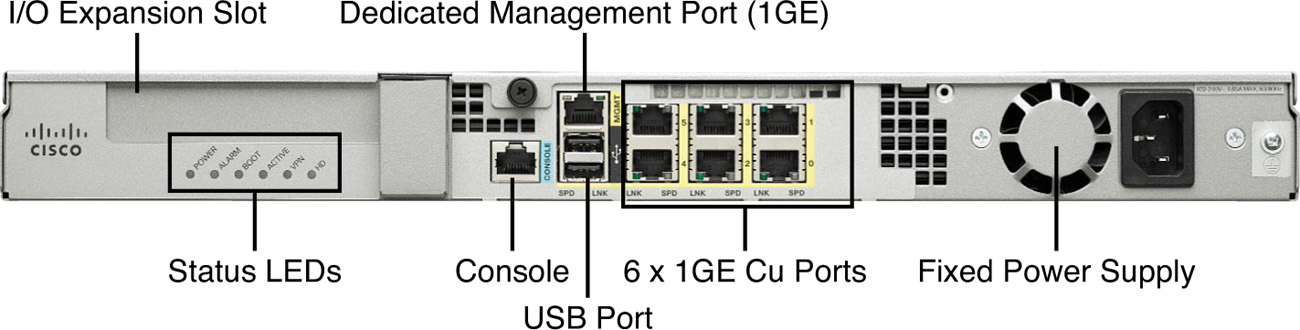
The Status LEDs display the following:
![]() Power: Solid green indicates that the power supply is on. Off indicates that the system is off.
Power: Solid green indicates that the power supply is on. Off indicates that the system is off.
![]() Alarm: Indicates if there is an alarm about the operating status of the appliance. When the LED is off, the appliance is functioning in normal conditions. When a flashing amber light appears, it indicates either that a major hardware failure has occurred, that the device is overheated, or that the power voltage is outside normal conditions.
Alarm: Indicates if there is an alarm about the operating status of the appliance. When the LED is off, the appliance is functioning in normal conditions. When a flashing amber light appears, it indicates either that a major hardware failure has occurred, that the device is overheated, or that the power voltage is outside normal conditions.
![]() Boot: On when the system is booting up. A flashing green light indicates that the system diagnostics are running during bootup. Solid green means that the appliance has passed all the booting diagnostics. The boot LED is off when the power-up diagnostics are not operational.
Boot: On when the system is booting up. A flashing green light indicates that the system diagnostics are running during bootup. Solid green means that the appliance has passed all the booting diagnostics. The boot LED is off when the power-up diagnostics are not operational.
![]() Active: When solid green, indicates that the failover pair (when failover is configured) is operational. The LED will be off when failover is not configured or operational.
Active: When solid green, indicates that the failover pair (when failover is configured) is operational. The LED will be off when failover is not configured or operational.
![]() VPN: When solid green, indicates that the VPN (IPsec or SSL) tunnel is established.
VPN: When solid green, indicates that the VPN (IPsec or SSL) tunnel is established.
![]() HD0: The Cisco ASA 5512-X, 5515-X, 5525-X, 5545-X, and 5555-X have internal hard disk drives (HDD). When the HD0 LED is flashing green, it indicates read and write activity in the HDD. If the HDD fails, a solid amber light is displayed. If the LED is off, then no hard disk is present or the system is powered off. The Cisco ASA 5512-X, 5515-X, and 5525-X have only one HDD. These are labeled as HD.
HD0: The Cisco ASA 5512-X, 5515-X, 5525-X, 5545-X, and 5555-X have internal hard disk drives (HDD). When the HD0 LED is flashing green, it indicates read and write activity in the HDD. If the HDD fails, a solid amber light is displayed. If the LED is off, then no hard disk is present or the system is powered off. The Cisco ASA 5512-X, 5515-X, and 5525-X have only one HDD. These are labeled as HD.
![]() HD1: When the HD0 LED is flashing green, it indicates read and write activity in the HDD. If the HDD fails, a solid amber light is displayed. If the LED is off, then no hard disk is present or the system is powered off. The Cisco ASA 5545-X and 5555-X have two SSDs and, as a result, have LEDs for HD0 and HD1.
HD1: When the HD0 LED is flashing green, it indicates read and write activity in the HDD. If the HDD fails, a solid amber light is displayed. If the LED is off, then no hard disk is present or the system is powered off. The Cisco ASA 5545-X and 5555-X have two SSDs and, as a result, have LEDs for HD0 and HD1.
The Cisco ASA 5512-X includes six integrated 10/100-Gigabit Ethernet network interfaces.
Each Fast Ethernet port has an activity LED and a link LED:
![]() The activity LED shows that data is passing on the network to which the port is attached.
The activity LED shows that data is passing on the network to which the port is attached.
![]() The link LED shows that the port is operational.
The link LED shows that the port is operational.
The Management port is reserved for OOB management. The RJ-45 console port enables you to physically connect to the appliance to access its CLI.
The Cisco ASA 5500-X Series models are the only appliances that support external USB flash drives for data storage. The Cisco ASA 5510, 5520, 5540, and 5550 use an external compact flash drive for additional storage, where disk1 becomes the unique identifier. The Cisco ASA 5500-X Series also uses disk1 as the external USB flash drive identifier. Disk0 is the internal Embedded USB (eUSB) on the Cisco ASA 5500-X Series, and disk1 is the disk label for the external USB drive. In this way, the system mounts only one partition. In other words, if a USB drive is inserted with more than one partition, only the first partition is mounted.
Note
The Cisco ASA 5500-X Series back panel has two USB slots, but only one is supported for Online Insertion and Removal (OIR). The first USB drive that is inserted has the highest priority. The administrator sees an error message on the console when a second USB device is introduced, to notify that an extra, unsupported USB flash drive was inserted. Removing either one of the USB devices does not change the priority.
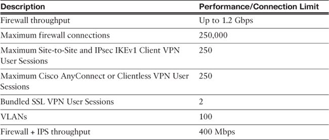
Table 2-3 lists the capabilities of the Cisco ASA 5512-X appliance and its performance and connection limit numbers.
Performance numbers vary depending on the packet size and which other applications are running on the appliance. For more information about licensing, go to http://www.cisco.com/c/en/us/support/security/asa-5500-series-next-generation-firewalls/products-licensing-information-listing.html.
Cisco ASA 5515-X Model
The Cisco ASA 5515-X model is also designed for small and medium-sized businesses and enterprise branch offices. As previously mentioned, the Cisco ASA 5512-X, 5515-X, 5525-X, 5545-X, and 5555-X provide advanced firewall and VPN capabilities and IPS services that do not require a hardware module. With the addition of a solid-state drive (SSD), these appliances may also run Next-Generation Firewall Services alongside the traditional Cisco ASA firewall features. The front and back views of the Cisco ASA 5515-X have the same design as those of the Cisco ASA 5512-X (shown earlier in Figures 2-8 and 2-9).
Table 2-4 lists the capabilities of the Cisco ASA 5515-X appliance and its performance and connection limit numbers.
Note
Performance numbers vary depending on the packet size and which other applications are running on the appliance. For more information about model descriptions, go to http://www.cisco.com/go/asa.
Cisco ASA 5520 Model
The Cisco ASA 5520 model provides security services for medium-sized enterprises. The Cisco ASA 5520 and 5540 models are similar to the Cisco ASA 5510 model. The Cisco ASA 5520 has four Gigabit Ethernet (10/100/1000) copper-based RJ-45 ports instead. It also includes a Fast Ethernet port for OOB management.
The front panel of the Cisco ASA 5520 has the same five LEDs that are present in the Cisco ASA 5510 (shown earlier in Figure 2-6 and described thereafter).
The back view of the Cisco ASA 5520 is identical to that of the Cisco ASA 5510 (shown earlier in Figure 2-7), except that the Cisco ASA 5520 has four Gigabit Ethernet (10/100/1000) ports, whereas the Cisco ASA 5510 has four Fast Ethernet ports.
With the installation of a VPN Plus upgrade license, the Cisco ASA 5520 can terminate up to 750 IPsec or WebVPN tunnels. Beginning with Cisco ASA Software version 7.1, SSL VPN (Web VPN) capability requires a license. The Cisco ASA supports two SSL VPN connections by default for evaluation and remote management purposes.
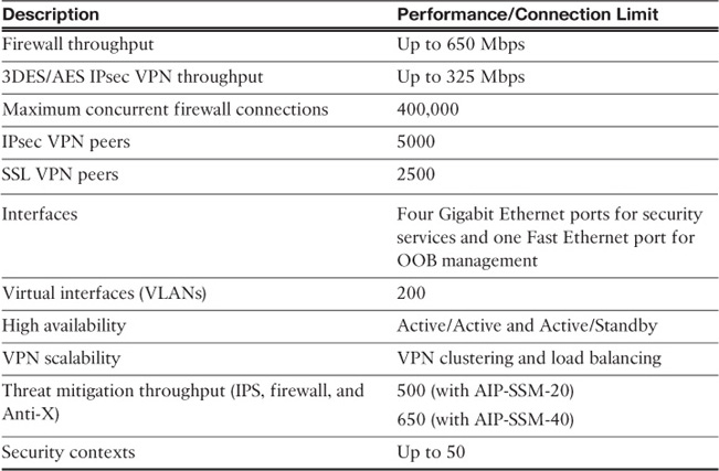
Table 2-5 lists the capabilities of the Cisco ASA 5520 appliance and its performance and connection limit numbers.

Note
Performance numbers vary depending on the packet size and which other applications are running on the appliance. For more information about licensing, go to http://www.cisco.com/go/asa.
Cisco ASA 5525-X Model
The Cisco ASA 5525-X model provides security services for medium-sized enterprises. The front and back views of the Cisco ASA 5512-X, 5515-X, and 5525-X have the same design (as shown earlier for the ASA 5512-X in Figures 2-8 and 2-9). The Cisco ASA 5525-X has eight Gigabit Ethernet (GE) interfaces.
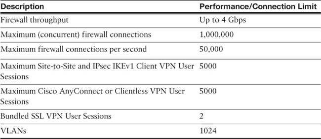
Table 2-6 lists the capabilities of the Cisco ASA 5525-X appliance and its performance and connection limit numbers.
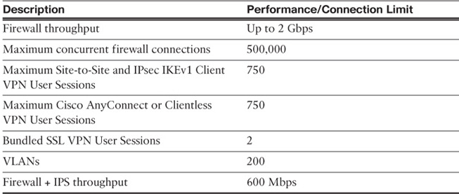
Performance numbers vary depending on the packet size and which other applications are running on the appliance. For more information about licensing and model descriptions, go to http://www.cisco.com/go/asa.
Cisco ASA 5540 Model
The Cisco ASA 5540 model provides security services to medium-sized enterprises. The Cisco ASA 5540 model supports a higher number of security contexts (50) to provide more flexibility and compartmentalized control of security policies. It also provides support for up to ten appliances in a VPN cluster, supporting a maximum of 50,000 IPsec VPN peers per cluster (25,000 for WebVPN).
The Cisco ASA 5540 is also a 1RU device. The external front and back layouts of the Cisco ASA 5540 appliance are identical to those of the Cisco ASA 5510 and 5520 appliances (see Figures 2-6 and 2-7 for front and back views of the Cisco ASA 5510). Table 2-7 lists the capabilities of the Cisco ASA 5540 appliance and its performance and connection limit numbers.
The Cisco ASA 5540 supports two SSL VPN connections by default for evaluation and remote management purposes.
Cisco ASA 5545-X Model
The Cisco ASA 5545-X model provides enhanced capabilities to those of its predecessor (Cisco ASA 5540). The front and back views of the Cisco ASA 5545-X are the same as those of the Cisco ASA 5512-X, 5515-X, 5525-X, 5545-X, and 5555-X (as shown earlier in Figures 2-8 and 2-9 for the Cisco ASA 5512-X). With the addition of a solid-state drive (SSD), these appliances may also run Next-Generation Firewall Services alongside the traditional ASA firewall features. The Cisco ASA 5545-X and 5555-X front panels have two slots to allow an administrator to install two SSDs. The Cisco ASA 5545-X and 5555-X can be configured with dual power supplies.
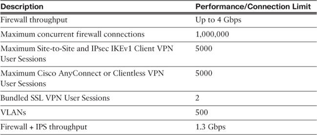
Table 2-8 lists the capabilities of the Cisco ASA 5545-X appliance and its performance and connection limit numbers.

Note
Performance numbers vary depending on the packet size and which other applications are running on the appliance. For more information about model descriptions, go to http://www.cisco.com/go/asa.
Cisco ASA 5550 Model
The Cisco ASA 5550 model provides high-availability security services for large enterprise and service-provider networks in a 1RU form factor. This model provides Gigabit Ethernet connectivity in the form of both Ethernet and fiber-based interfaces.
The external front layout of the Cisco ASA 5550 appliance is identical to that of the Cisco ASA 5510, 5520, and 5540 appliances (refer to Figure 2-6 to see the front view of the Cisco ASA 5510). The Cisco ASA 5550 appliances have two internal buses, providing copper Gigabit Ethernet and fiber Gigabit Ethernet connectivity:
![]() Slot 0 corresponds to B and has four embedded copper Gigabit Ethernet ports.
Slot 0 corresponds to B and has four embedded copper Gigabit Ethernet ports.
![]() Slot 1 corresponds to Bus 1 and has four embedded copper Gigabit Ethernet ports and four embedded Small Form-Factor Pluggable (SFP) interfaces that support fiber Gigabit Ethernet connectivity.
Slot 1 corresponds to Bus 1 and has four embedded copper Gigabit Ethernet ports and four embedded Small Form-Factor Pluggable (SFP) interfaces that support fiber Gigabit Ethernet connectivity.
Tip
To maximize traffic throughput, configure the Cisco ASA 5550 so that traffic is distributed equally between the two buses in the device. In other words, configure and lay out the network interfaces so that all traffic connections flow through both Bus 0 (Slot 0) and Bus 1 (Slot 1), entering through one bus and exiting through the other.
Slot 1 has four copper Ethernet ports and four fiber Ethernet ports; however, you can use only four Slot 1 ports at a time. For instance, you could use two Slot 1 copper ports and two fiber ports, but you cannot use fiber ports if you are already using all four Slot 1 copper ports.
Table 2-9 lists the capabilities of the Cisco ASA 5550 and its performance and connection limit numbers.

The Cisco ASA 5500 supports two SSL VPN connections by default for evaluation and remote management purposes.
Cisco ASA 5555-X Model
The Cisco ASA 5555-X model is the largest of the Cisco ASA 5500-X midrange security appliances. Table 2-10 lists the capabilities of the Cisco ASA 5555-X appliance and its performance and connection limit numbers. The Cisco ASA 5545-X and 5555-X front panels have two slots to allow an administrator to install two SSDs. The Cisco ASA 5545-X and 5555-X can be configured with dual power supplies.
Note
Performance numbers vary depending on the packet size and which other applications are running on the appliance. For more information about model descriptions, go to http://www.cisco.com/go/asa.
Cisco ASA 5585-X Models
The Cisco ASA 5585-X Series models are the largest of the appliance family. They are typically used in areas of the network that have very high demand, such as the data centers, as they can handle very high data volumes (up to 40 Gbps per firewall module). The Cisco ASA 5585-X appliances are designed in a 2RU fashion (two-slot chassis) supporting up to two AC power supply modules. The Cisco ASA 5585-X comes in four different models. These modules include different types of Security Services Processor (SSP):
![]() Cisco ASA 5585-X SSP-10: Ten interfaces (two 10-Gigabit Ethernet SFP/SFP+ and eight copper Gigabit Ethernet) with one power supply module and one fan module
Cisco ASA 5585-X SSP-10: Ten interfaces (two 10-Gigabit Ethernet SFP/SFP+ and eight copper Gigabit Ethernet) with one power supply module and one fan module
![]() Cisco ASA 5585-X SSP-20: Ten interfaces (two 10-Gigabit Ethernet SFP/SFP+ and eight copper Gigabit Ethernet) with one power supply module and one fan module
Cisco ASA 5585-X SSP-20: Ten interfaces (two 10-Gigabit Ethernet SFP/SFP+ and eight copper Gigabit Ethernet) with one power supply module and one fan module
![]() Cisco ASA 5585-X SSP-40: Ten interfaces (four 10-Gigabit Ethernet SFP/SFP+ and six copper Gigabit Ethernet) with one power supply module and one fan module
Cisco ASA 5585-X SSP-40: Ten interfaces (four 10-Gigabit Ethernet SFP/SFP+ and six copper Gigabit Ethernet) with one power supply module and one fan module
![]() Cisco ASA 5585-X SSP-60: Ten interfaces (four 10-Gigabit Ethernet SFP/SFP+ and six copper Gigabit Ethernet) with two power supply modules and one fan module
Cisco ASA 5585-X SSP-60: Ten interfaces (four 10-Gigabit Ethernet SFP/SFP+ and six copper Gigabit Ethernet) with two power supply modules and one fan module
Tip
The fan modules in the Cisco ASA 5585-X SSP-10, SSP-20, and SSP-40 can be replaced with another power supply module for redundancy.
The SSPs are always placed in slot 0 (the bottom slot), and slot 1 (the top slot) is used for an additional SSP. Examples are the Cisco Intrusion Prevention System Security Services Processor (IPS SSP) or the Cisco ASA 5585-X CX Security Services Processor (ASA CX SSP), or up to two network modules or SSP modules. Figure 2-10 shows the front view of a Cisco ASA 5585-X with two SSPs.
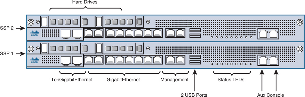
In Figure 2-10, the two SSPs are labeled SSP 1 and SSP 2. Each SSP has two Ten Gigabit Ethernet ports and eight Gigabit Ethernet ports. Two additional management ports are also included. All port numbers are numbered from right to left beginning with 0.
The Cisco ASA 5500-X Series also uses disk1 as the external USB flash drive identifier. Disk0 is the internal eUSB on the Cisco ASA 5500-X Series.
The Status LEDs display the following:
![]() Power: Solid green indicates that the power supply is on. Off indicates that the system is off.
Power: Solid green indicates that the power supply is on. Off indicates that the system is off.
![]() Alarm: Indicates if there is an alarm about the operating status of the appliance. When the LED is off, the appliance is functioning in normal conditions. When a flashing amber light appears, it indicates either that a major hardware failure has occurred, that the device is overheated, or that the power voltage is outside normal conditions.
Alarm: Indicates if there is an alarm about the operating status of the appliance. When the LED is off, the appliance is functioning in normal conditions. When a flashing amber light appears, it indicates either that a major hardware failure has occurred, that the device is overheated, or that the power voltage is outside normal conditions.
![]() Boot: On when the system is booting up. A flashing green light indicates that the system diagnostics are running during bootup. Solid green means that the appliance has passed all the booting diagnostics. The boot LED is off when the power-up diagnostics are not operational.
Boot: On when the system is booting up. A flashing green light indicates that the system diagnostics are running during bootup. Solid green means that the appliance has passed all the booting diagnostics. The boot LED is off when the power-up diagnostics are not operational.
![]() Active: When solid green, indicates that the failover pair (when failover is configured) is operational. The LED will be off when failover is not configured or operational. If the Cisco ASA is configured as a standalone appliance, this LED will be on.
Active: When solid green, indicates that the failover pair (when failover is configured) is operational. The LED will be off when failover is not configured or operational. If the Cisco ASA is configured as a standalone appliance, this LED will be on.
![]() VPN: When solid green, indicates that the VPN (IPsec or SSL) tunnel is established.
VPN: When solid green, indicates that the VPN (IPsec or SSL) tunnel is established.
![]() HD0: The Cisco ASA 5585-X has an internal hard disk drive (HDD). When the HD0 LED is flashing green, it indicates read and write activity in the HDD. If the HDD fails, a solid amber light is displayed. If the LED is off, then no hard disk is present or the system is powered off.
HD0: The Cisco ASA 5585-X has an internal hard disk drive (HDD). When the HD0 LED is flashing green, it indicates read and write activity in the HDD. If the HDD fails, a solid amber light is displayed. If the LED is off, then no hard disk is present or the system is powered off.
![]() HD1: When the HD1 LED is flashing green, it indicates read and write activity in the HDD. If the HDD fails, a solid amber light is displayed. If the LED is off, then no hard disk is present or the system is powered off.
HD1: When the HD1 LED is flashing green, it indicates read and write activity in the HDD. If the HDD fails, a solid amber light is displayed. If the LED is off, then no hard disk is present or the system is powered off.
The RJ-45 Auxiliary port (labeled AUX on the chassis) is reserved for internal use at Cisco. The RJ-45 console port enables you to physically connect to the appliance to access its CLI.
Table 2-11 lists the capabilities of the Cisco ASA 5585-X appliance with an SSP-10 and its performance and connection limits.
Performance numbers vary depending on the packet size and which other applications are running on the appliance. For more information about model descriptions, go to http://www.cisco.com/go/asa.
Table 2-12 lists the capabilities of the Cisco ASA 5585-X appliance with an SSP-20 and its performance and connection limits.
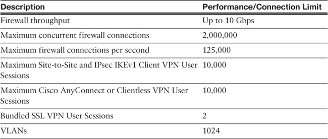
Table 2-13 lists the capabilities of the Cisco ASA 5585-X appliance with an SSP-40 and its performance and connection limits.

Table 2-14 lists the capabilities of the Cisco ASA 5585-X appliance with an SSP-60 and its performance and connection limits.

As previously mentioned, the Cisco ASA 5585-X models are typically used in areas of the network with very high demand, such as the data centers. Figure 2-11 illustrates an example of an enterprise data center (high-level diagram) where the Cisco ASA 5585-X is placed in several strategic locations to provide isolation between several server zones and complete control of the data center aggregation layer.
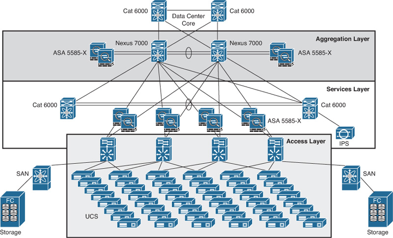
If you are not familiar with data center technologies and related products, several resources are available at the Cisco Data Center and Virtualization website: http://www.cisco.com/go/datacenter.
Cisco Catalyst 6500 Series ASA Services Module
The Cisco Catalyst 6500 Series ASA Services Module (ASASM) is the replacement for the Cisco Catalyst 6500 Firewall Services Module (FWSM). The Cisco ASA Services Module is designed in a single-blade architecture, providing a maximum firewall throughput of 20 Gbps and 16 Gbps with multiprotocol traffic. It supports 10 million concurrent connections; 300,000 connections per second; and 1000 VLANs. The Cisco ASA Services Module does not include any external physical interfaces. Instead, it uses VLAN interfaces. Assigning VLANs to the Cisco ASASM is similar to assigning a VLAN to a switch port; the Cisco ASASM includes an internal interface to the Switch Fabric Module (if present) or the shared bus.
Tip
For a scalability of up to 64 Gbps, four Cisco ASA Services Modules can be installed in a Cisco Catalyst 6500 Series Switch.
Chapter 6, “Cisco ASA Services Module,” covers the Cisco Catalyst 6500 Series ASA Services Module in detail.
Cisco ASA 1000V Cloud Firewall
The Cisco ASA 1000V Cloud Firewall is a virtual firewall that was designed using the Cisco ASA Software architecture to secure the tenant edge in multitenant environments with Nexus 1000V deployments. It supports common edge features such as site-to-site VPN and Network Address Translation (NAT) and acts as a default gateway to protect the virtual machines (VM) within the virtual tenants. The Cisco ASA 1000V Cloud Firewall is deployed with the following components:
![]() VMware vCenter VSphere Hypervisor software (required software for installing the Cisco Nexus 1000V and the Cisco Virtual Network Management Center [VNMC])
VMware vCenter VSphere Hypervisor software (required software for installing the Cisco Nexus 1000V and the Cisco Virtual Network Management Center [VNMC])
![]() Cisco Prime Network Services Controller
Cisco Prime Network Services Controller
![]() VMware vCenter Server software
VMware vCenter Server software
![]() Cisco Nexus 1000V
Cisco Nexus 1000V
![]() Cisco Virtual Network Management Center (single-point manager for both the Cisco ASA 1000V Cloud Firewall and Cisco Virtual Security Gateway [VSG])
Cisco Virtual Network Management Center (single-point manager for both the Cisco ASA 1000V Cloud Firewall and Cisco Virtual Security Gateway [VSG])
![]() (Optional) Cisco Virtual Security Gateway to provide segmentation between VMs
(Optional) Cisco Virtual Security Gateway to provide segmentation between VMs
Note
The Cisco VSG is required to segment inter-VM traffic within a tenant.
Figure 2-12 shows a very simple example of how the Cisco ASA 1000V Cloud Firewall is virtually connected to a Cisco Nexus 1000V virtual switch protecting four VMs.
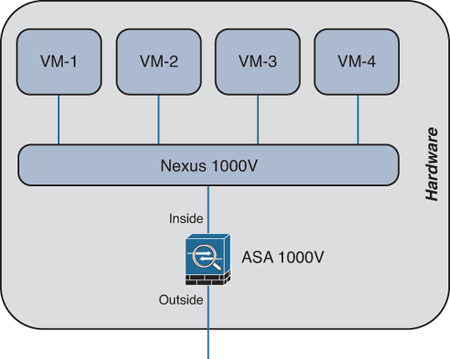
The Cisco ASA 1000V Cloud Firewall supports a maximum of 200,000 concurrent firewall sessions and 10,000 connections per second. It also supports a maximum of 750 VPN tunnels with a total throughput of 200 Mbps.
Cisco ASA Next-Generation Firewall Services (Formerly Cisco ASA CX)
Cisco ASA Next-Generation Firewall Services provides numerous capabilities to maintain complete visibility and control that traditional firewalls do not provide. These capabilities allow organizations to adapt to today’s fast-paced and dynamic environment in which new applications and devices pop up everywhere within the corporate network—and allows them to do so without compromising security. The Cisco ASA Next-Generation Firewall Services also uses global threat intelligence from Cisco Security Intelligence Operations (SIO) to provide zero-day malware protection. It recognizes more than 1000 applications and 75,000 micro applications, enabling organizations to provide access to specific components of an application. For example, an administrator can allow the usage of Facebook, Twitter, and any other social networking sites for an individual user while disabling other components such as games, video uploads, etc. Policies can be written for individual users or group-based access control.
Cisco ASA AIP-SSM Module
The following are the three Adaptive Inspection and Prevention Security Services Module (AIP-SSM) models, which provide support for IPS services delivered by Cisco IPS Software:
![]() AIP-SSM-10: Supported only on the Cisco ASA 5510 and 5520 appliances.
AIP-SSM-10: Supported only on the Cisco ASA 5510 and 5520 appliances.
![]() AIP-SSM-20: Supported only on the Cisco ASA 5510, 5520, and 5540 appliances.
AIP-SSM-20: Supported only on the Cisco ASA 5510, 5520, and 5540 appliances.
![]() AIP-SSM-40: Supported only on the Cisco ASA 5520 and 5540 appliances.
AIP-SSM-40: Supported only on the Cisco ASA 5520 and 5540 appliances.
The Cisco ASA 5512-X, 5515-X, 5525-X, 5545-X, and 5555-X provide built-in IPS services.
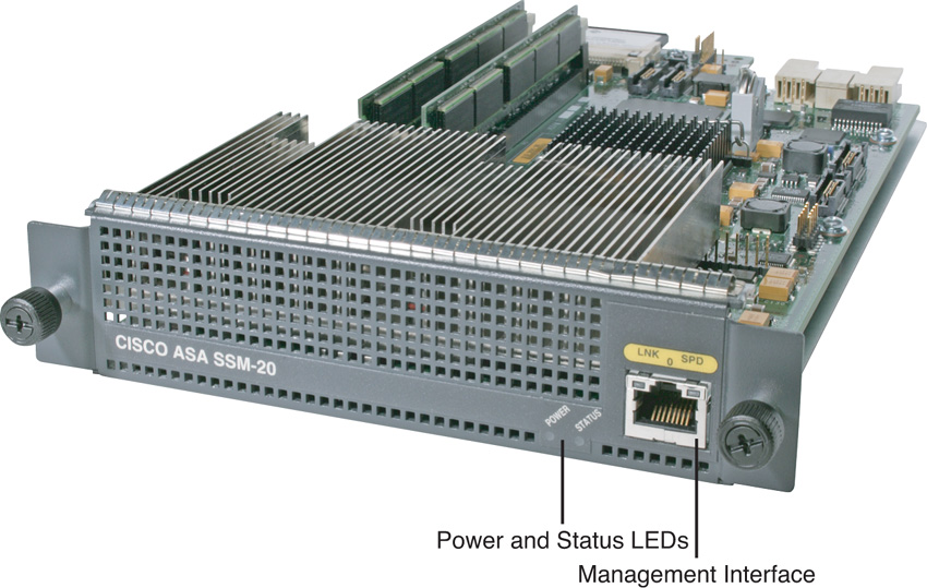
All the Cisco AIP-SSM modules have the same physical characteristics. Figure 2-13 shows the Cisco AIP-SSM-20 module.
Cisco ASA AIP-SSM-10
The Cisco ASA AIP-SSM-10 concurrent threat mitigation throughput can scale to up to 150 Mbps with the Cisco ASA 5510 and up to 225 Mbps with the Cisco ASA 5520. It comes with 1 GB of RAM and 256 MB of flash memory.
Cisco ASA AIP-SSM-20
The Cisco ASA AIP-SSM-20 concurrent threat mitigation throughput can scale to up to 300 Mbps with the Cisco ASA 5510, up to 375 Mbps with the Cisco ASA 5520, and up to 500 Mbps with the Cisco ASA 5540. It comes with 2 GB of RAM and 256 MB of flash memory.
Cisco ASA AIP-SSM-40
The Cisco ASA AIP-SSM-40 concurrent threat mitigation throughput can scale to up to 450 Mbps with the Cisco ASA 5520 and up to 650 Mbps with the Cisco ASA 5540. It comes with 4 GB of RAM and 2 GB of flash memory.
Note
Configuration and troubleshooting of the Cisco ASA AIP-SSM modules is covered in Chapter 17, “Implementing ASA Intrusion Prevention System (IPS).”
Cisco ASA Gigabit Ethernet Modules
There are several Gigabit Ethernet expansion modules for the Cisco ASA appliances.
The Cisco ASA 5510, 5520, 5540, and 5550 support the Cisco ASA 4-Port Gigabit Ethernet Security Services Module (SSM-4GE).
Note
The Cisco ASA 5550 is already equipped with this module.
The Cisco ASA 5580-20 and 5580-40 support the following modules:
![]() 4-port Gigabit Ethernet copper PCI Express card
4-port Gigabit Ethernet copper PCI Express card
![]() 2-port 10-Gigabit Ethernet fiber PCI Express card
2-port 10-Gigabit Ethernet fiber PCI Express card
![]() 4-port Gigabit Ethernet fiber PCI Express card
4-port Gigabit Ethernet fiber PCI Express card
Cisco ASA 5500-X Series 6-port GE Interface Cards extend the Cisco ASA 5512-X and Cisco ASA 5515-X by providing additional Gigabit Ethernet ports.
Cisco ASA SSM-4GE
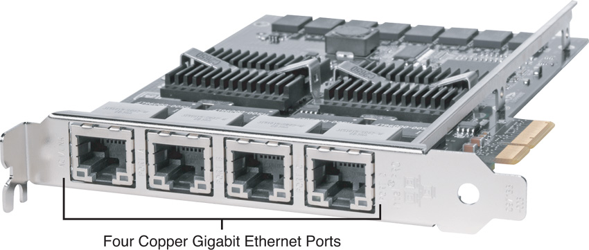
The Cisco ASA SSM-4GE has four 10/100/1000 RJ-45 ports and four Small Form-Factor Pluggable (SFP) ports to support both copper and optical connections. You can choose copper or fiber connectivity for each of the four ports, providing flexibility for data center, campus, or enterprise edge connectivity (with a maximum of four ports in service concurrently). The Cisco ASA SSM-4GE expands the Cisco ASA 5510 with a Security Plus license to three Fast Ethernet and six Gigabit Ethernet ports. Similarly, it expands the Cisco ASA 5520 and 5540 appliances to eight Gigabit Ethernet ports and one Fast Ethernet management port. Figure 2-14 illustrates the Cisco ASA SSM-4GE.

Cisco ASA 5580 Expansion Cards
The Cisco ASA 5580 4-Port Gigabit Ethernet Copper PCI Express Card provides four 10/100/1000BASE-T interfaces, which allow up to 24 total Gigabit Ethernet interfaces in a fully populated chassis. Figure 2-15 shows the 4-Port Gigabit Ethernet Copper PCI Express Card.
The Cisco ASA 5580 4-Port Gigabit Ethernet Fiber PCI Express Card provides four 1000BASE-SX (fiber) interfaces, expanding to up to 24 total Gigabit Ethernet fiber interfaces in a fully populated chassis. Figure 2-16 shows the 4-Port Gigabit Ethernet Fiber PCI Express Card.

Note
The 4-Port Gigabit Ethernet Fiber PCI Express Card ports require a multimode fiber cable with an LC connector to connect to the SX interface of the chassis.
The Cisco ASA 5580 2-Port 10-Gigabit Ethernet Fiber PCI Express Card provides two 1000BASE-SX (fiber) interfaces, expanding to up to 12 total 10-Gigabit Ethernet fiber interfaces in a fully populated chassis.
The 2-Port 10-Gigabit Ethernet Fiber PCI Express Card ports require a multimode fiber cable with an LC connector to connect to the SX interface of the chassis.
Figure 2-17 shows the 2-Port 10-Gigabit Ethernet Fiber PCI Express Card.

Cisco ASA 5500-X Series 6-Port GE Interface Cards
Cisco ASA 5500-X Series 6-Port GE Interface Cards extend the Cisco ASA 5512-X and Cisco ASA 5515-X by providing additional Gigabit Ethernet ports. These cards offer better segmentation of network traffic (into separate security zones) and fiber-optic cable connectivity for long-distance communication. They also provide load sharing of traffic, protection against link failure through the use of EtherChannel, and support for jumbo Ethernet frames of up to 9000 bytes. These cards come in two different flavors:
![]() Cisco ASA 5500-X Series 6-Port 10/100/1000
Cisco ASA 5500-X Series 6-Port 10/100/1000
![]() Cisco ASA 5500-X Series 6-Port GE SFP SX, LH, and LX
Cisco ASA 5500-X Series 6-Port GE SFP SX, LH, and LX
Summary
This chapter provided a hardware overview of all Cisco ASA 5500 and ASA 5500-X Series Next-Generation Firewalls, the Cisco Catalyst 6500 Series ASA Services Module, the Cisco ASA 1000V Cloud Firewall, and the Cisco ASA CX. It also provided an overview of the additional modules supported in each platform. The Cisco ASA product family offers a broad range of firewall, VPN, application inspection, IPS, Secure-X, and context-aware services that are used in small, medium-sized, and large enterprises. In-depth technical information for each feature and capability is provided in subsequent chapters.