Chapter 10. Network Address Translation
This chapter covers the following topics:
![]() Address translation types
Address translation types
![]() Security protection mechanisms within address translation
Security protection mechanisms within address translation
![]() Understanding address translation behavior
Understanding address translation behavior
![]() Configuring address translation
Configuring address translation
![]() Monitoring address translations
Monitoring address translations
Cisco ASA acts as a network firewall and can help protect one or more networks from intruders and attackers. Chapter 8, “Controlling Network Access: The Traditional Way,” and Chapter 9, “Implementing Next-Generation Firewall Services with ASA CX,” discussed the use of access control lists and other identity-based enforcement features to protect an infrastructure. The other core security feature of a firewall is its capability to mask the network address on the trusted side from the untrusted networks. This technique, commonly referred to as address translation, allows an organization to hide the internal addressing scheme from the outside by displaying a different IP address space. Address translation is useful in the following network deployments:
![]() You use a private addressing scheme internally and want to assign global routable addresses to those hosts.
You use a private addressing scheme internally and want to assign global routable addresses to those hosts.
![]() You change to a service provider that requires you to modify your addressing scheme. Rather than redesigning the entire IP infrastructure, you implement translation on the border appliance.
You change to a service provider that requires you to modify your addressing scheme. Rather than redesigning the entire IP infrastructure, you implement translation on the border appliance.
![]() For security reasons, you do not want to advertise the internal addressing scheme to the outside hosts.
For security reasons, you do not want to advertise the internal addressing scheme to the outside hosts.
![]() You have multiple internal networks that require Internet connectivity through the security appliance, but only one global address (or a few) is available for translation.
You have multiple internal networks that require Internet connectivity through the security appliance, but only one global address (or a few) is available for translation.
![]() You have overlapping networks in your organization and you want to provide connectivity between the two without modifying the existing addressing scheme.
You have overlapping networks in your organization and you want to provide connectivity between the two without modifying the existing addressing scheme.
Types of Address Translation
Cisco ASA supports two types of address translation, namely Network Address Translation (NAT) and Port Address Translation (PAT).
Network Address Translation
Network Address Translation (NAT) defines a one-to-one address mapping when a packet passes through the security appliance and matches criteria for translation. The security appliance either assigns a static IP address (static NAT) or allocates an address from a pool of addresses (dynamic NAT).
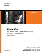
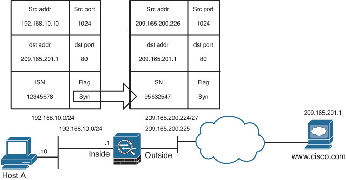
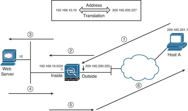
Cisco ASA can translate an internal address to a global address when packets are destined for the public network. With this method, also known as inside NAT, the security appliance converts the global address of the return traffic to the original internal address. Inside NAT is used when traffic originates from a higher security–level interface, such as the inside interface, and is destined for a lower security–level interface, such as the outside interface. In Figure 10-1, a host on the internal network, 192.168.10.10, sends traffic to a host on the outside network, 209.165.201.1. The Cisco ASA converts the source IP address to 209.165.200.226 while keeping the destination IP address intact. When the web server responds to the global IP address, 209.165.200.226, the security appliance reverts the global IP address to the original internal IP address of 192.168.10.10.

Optionally, the hosts on the lower security–level interface can be translated when traffic is destined for a host on the higher security–level interface. This method, known as outside NAT, is useful when you want a host on the outside network to appear as one of the internal IP addresses. In Figure 10-2, a host on the outside network, 209.165.201.1, sends traffic to a host on the inside network, 192.168.10.10, by using its global IP address as the destination address. Cisco ASA converts the source IP address to 192.168.10.100 while changing the destination IP address to 192.168.10.10. Because both the source and destination IP addresses are changing, this is also known as bidirectional NAT.

Note
If the packets are denied by the interface ACLs, the security appliance does not build the corresponding address translation table entry.
Port Address Translation
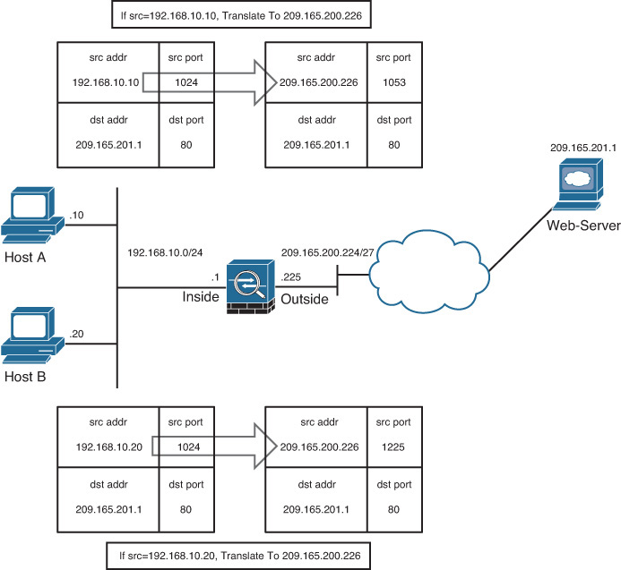
Port Address Translation (PAT) defines a many-to-one address mapping when a packet passes through the security appliance and matches criteria for translation. The security appliance creates the translation table by looking at the Layer 4 information in the header to distinguish between the inside hosts using the same global IP address.
Figure 10-3 illustrates an appliance set up for PAT for the inside network of 192.168.10.0/24. However, only one global address is available for translation. If two inside hosts, 192.168.10.10 and 192.168.10.20, require connectivity to an outside host, 209.165.201.1, the security appliance builds the translation table by evaluating the Layer 4 header information. In this case, because both inside hosts have the same source port number, the security appliance assigns a random source port number to keep both entries unique from each other. This way, when the response from the web server returns to the security appliance, the security appliance knows which inside host to forward the packets.
Address Translation Methods
Cisco ASA supports the following four methods to translate an address:
![]() Static NAT/PAT
Static NAT/PAT
![]() Dynamic NAT/PAT
Dynamic NAT/PAT
![]() Policy NAT/PAT
Policy NAT/PAT
![]() Identity NAT
Identity NAT
Static NAT/PAT
Static NAT defines a fixed translation of an inside host or subnet address to a global routable address or subnet. The security appliance uses the one-to-one methodology by assigning one global IP address to one inside IP address. Thus, if 100 hosts residing on the inside network require address translation, the security appliance should be configured for 100 global IP addresses. Additionally, the inside hosts are assigned the same IP address whenever the security appliance translates the packets going through it. This is a recommended solution in scenarios in which an organization provides services such as email, web, DNS, and FTP for outside users. Using static NAT, the servers use the same global IP address for all the inbound and outbound connections.
Static PAT, also known as port redirection, is useful when the security appliance needs to statically map multiple inside servers to one global IP address. Port redirection is applied to traffic when it passes through the security appliance from a lower security–level interface to a higher security–level interface. The outside hosts connect to the global IP address on a specific TCP or UDP port, which the security appliance redirects to the appropriate internal server, as shown in Figure 10-4.
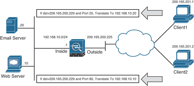
The security appliance redirects traffic destined for 209.165.200.229 on TCP port 80 to 192.168.10.10. Similarly, any traffic destined for 209.165.200.229 on TCP port 25 is redirected to 192.168.10.20.
The security appliance allows the use of either a dedicated IP address or the global interface’s IP address for port redirection.
When port redirection is set up to use the public interface’s IP address, the security appliance uses the same address for
![]() Address translation for the traffic traversing through the security appliance.
Address translation for the traffic traversing through the security appliance.
![]() Traffic destined for the security appliance.
Traffic destined for the security appliance.
Note
In IP telephony deployments where the Cisco CallManager server resides on the inside network and the IP phones connect from the outside network, the security appliance does not support outside NAT or PAT.
Dynamic NAT/PAT
Dynamic NAT assigns a random IP address from a preconfigured pool of global IP addresses. The security appliance uses a one-to-one methodology by allocating one global IP address to an inside IP address. Hence, if 100 hosts reside on the inside network, then you have at least 100 addresses in the pool of addresses. This is a recommended solution in scenarios in which an organization uses protocols that don’t contain Layer 4 information, such as Generic Routing Encapsulation (GRE), Reliable Datagram Protocol (RDP), and Data Delivery Protocol (DDP). After the security appliance has built a dynamic NAT entry for an inside host, any outside machine can connect to the assigned translated address, assuming that the security appliance allows the inbound connection.
With dynamic PAT, the security appliance builds the address translation table by looking at the Layer 3 and Layer 4 header information. It is the most commonly deployed scenario because multiple inside machines can get outside connectivity through one global IP address. In dynamic PAT, the security appliance uses the source IP addresses, the source ports, and the IP protocol information (TCP or UDP) to translate an inside host. As with static PAT, you have the option of using either a dedicated public address or the IP address of an interface for translations. As shown in Figure 10-5, two inside machines are accessing an external web server, using the IP address of the outside interface.

The security appliances randomize the source ports based on an enhancement included in version Cisco ASA Software versions 8.0(4), 8.1(2), and 8.2(1).
The security appliance supports up to 65,535 PAT translations using a single address. In Cisco ASA Software version 8.4(3) or higher, you can also use extended PAT, which allows you to have 65,525 PAT translations per service as opposed to per address.
Policy NAT/PAT
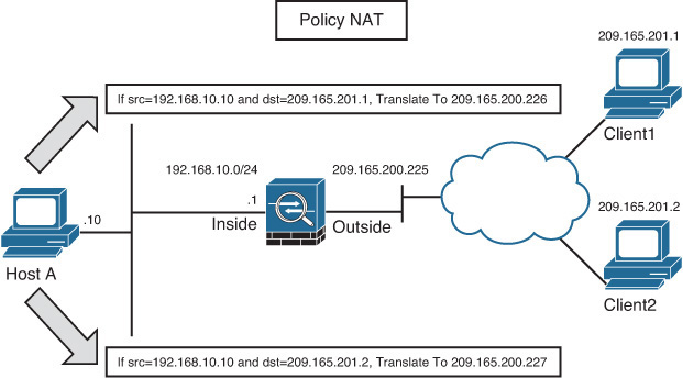
Policy NAT/PAT translates the IP address of the packets passing through the security appliance only if those packets match a defined criterion or policy. You define the policy by identifying interesting traffic through the use of ACLs or by using Manual NAT (if running Cisco ASA Software version 8.3 or higher) by identifying specific traffic. If traffic matches the defined entries in the ACL, then the original source or destination address can be translated to a different address. As illustrated in Figure 10-6, an administrator has defined a policy to translate the source IP address to 209.165.200.226 if the packets originate from 192.168.10.10 and are destined for 209.165.201.1. Similarly, if the packets are sourced from 192.168.10.10 and destined for a different address, say 209.165.201.2, the security appliance changes the source IP address to 209.165.200.227.
Identity NAT
In many scenarios, you want to bypass address translation so that the security appliance does not change the source or the destination address. You may want to bypass address translation, also known as identity NAT, if you already have address translation defined for the inside network so that hosts can get Internet connectivity. However, you do not want to change their addresses if they send traffic to a specific host or network.
Security Protection Mechanisms Within Address Translation
The security appliance offers a number of security features to protect the traffic passing through it. The following subsections discuss the two important features: randomization of sequence numbers and TCP Intercept.
Randomization of Sequence Numbers
Address translation not only masquerades the original IP address; it also provides protection against TCP connection hijacking for hosts with weak SYN implementation. When a packet enters the higher security–level interface and is destined for a lower security–level interface during the TCP three-way handshake, the security appliance randomizes the original sequence numbers used by the hosts. This process is illustrated in Figure 10-7. When the host 192.168.10.10 sends a TCP SYN HTTP packet to host 209.165.201.1 with an initial sequence number (ISN) of 12345678, the Cisco ASA changes the source IP address to 209.165.200.226 and also modifies the ISN to a randomly generated value of 95632547.
In some deployment scenarios, such as Border Gateway Protocol (BGP) peering with MD5 authentication, it is recommended to turn off the randomization of TCP packets. When two routers establish BGP peering with each other, the TCP header and data payload are 128-bit hashed, using the BGP password. When the sequence number is changed, the peering router fails to authenticate the packets because of the mismatched hash. For more information about BGP MD5 authentication, consult RFC 2385. You can disable sequence randomization via the Modular Policy Framework (MPF), discussed in Chapter 13, “Application Inspection.”
TCP Intercept
TCP Intercept is a security feature that protects the TCP-based servers from TCP SYN attacks by filtering the bogus denial-of-service (DoS) traffic. The TCP Intercept feature is configured using the MPF to set connection limits. The security appliance also protects network resources from an unexpected increase in the number of connections by setting maximum limits. This is applicable for both TCP- and UDP-based connections. Example 10-1 illustrates the MPF being used to set the maximum connection limit to 1500 and the embryonic connection limit to 2000 for all traffic traversing the outside interface.
Example 10-1 Example of TCP Intercept
Chicago(config)# class-map TCPIntercept
Chicago(config-cmap)# match any
Chicago(config-cmap)# policy-map TCPInterceptPolicy
Chicago(config-pmap)# class TCPIntercept
Chicago(config-pmap-c)# set connection conn-max 1500 embryonic-conn-max 2000
Chicago(config-pmap-c)# service-policy TCPInterceptPolicy interface outside
Note
The TCP Intercept option should be deployed with caution. If a host or network is under attack, the TCP Intercept feature can overwhelm the CPU and memory resources of the security appliance. The security appliance, in other words, can become the bottleneck in such a scenario.
Understanding Address Translation Behavior
Depending on the version of Cisco ASA Software you are using on the security appliance, you may encounter different behavior for the address translation functionality.
Address Translation Behavior Prior to Version 8.3
In Cisco ASA Software version prior to 8.3 (pre-8.3), an address translation policy is not required, by default, when the inside machines (host toward the higher security–level interface) access the hosts on the outside network (resources toward the lower security–level interface). However, if a packet matches a NAT/PAT policy, the security appliance translates the address. If packets do not match a policy, they are sent out without being translated.
Some organizations mandate that a translation policy be defined before hosts send traffic through their firewalls. To meet that requirement, you can enable the nat-control feature on the security appliance. If implemented, any traffic trying to pass through the security appliance without an address translation policy is dropped. Even if you do not want to translate an address but the nat-control feature is turned on, you must define a policy to bypass address translation. Table 10-1 discusses the NAT behavior in pre-8.3 versions with and without the nat-control feature when traffic traverses the interfaces with different security-levels.
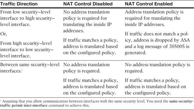
As mentioned in Table 10-1, address translation is not required when traffic passes between the interfaces with the same security level, even if the NAT-control feature is enabled. However, if a dynamic NAT/PAT policy is enabled with the NAT-control feature, the security appliance performs address translation for the traffic matching the policy even if this traffic is traversing the interfaces with the same security-level.
Note
If NAT rules are defined for the traffic between the same security interfaces, the security appliance does not support any Voice over IP (VoIP) inspection engines such as Skinny, SIP, and H.323. Additionally, traffic flows are still subject to the inspection rules even if NAT rules are defined for traffic that is traversing the interfaces with the same secureity-level.
Packet Flow Sequence in Pre-8.3 Version
When a packet passes through an appliance configured for address translation, the following sequence of events occurs:
1. The packet arrives at the ingress interface from the end host.
2. The security appliance checks to see whether the packet is a part of an existing connection. If it matches an existing connection, the processing function skips to Step 4. If the packet is not a part of an existing connection, and that packet is the first packet in a flow (for example, a SYN packet for TCP), the packet is evaluated against the inbound ACL applied on the ingress interface.
3. If the packet is allowed in, the security appliance first checks to see whether a translation with a global IP address matching the destination of the packet exists on the interface where the packet is received. A quick route lookup is done only to determine the egress interface. If there is a match, the packet is “virtually forwarded” to the interface of the translated address, skipping the global routing table check. If there is no translation matching the destination IP address of the packet on that ingress interface, proceed to Step 4.
4. If address translation is enabled and the packet matches the translation criteria, the security appliance creates a translation for the host.
5. On the egress interface, the security appliance consults the routing table to ensure only routes pointing to the egress interface are eligible.
6. The security appliance creates a stateful connection entry for the TCP and UDP packets. The security appliance can, optionally, create a stateful connection entry for ICMP traffic if ICMP inspection is turned on.
7. At the egress interface, the packet is transmitted.
NAT Order of Operation for Pre-8.3 Versions
In many network scenarios, it is necessary to configure different types of address translation on a single security appliance. To adapt to those scenarios, the security appliance needs to prioritize certain NAT rules over others to make sure that it knows what to do if there is a conflict. You must maintain the order of these rules/steps as listed to ensure they are properly set up:
1. NAT exemption—When multiple NAT types/rules are established, the security appliance tries to match traffic against the ACL in the NAT exemption rules. If a match is found, the corresponding NAT exemption policy is applied.
2. Static NAT—If no match is found in the NAT exemption rules, the security appliance analyzes the static NAT entries in sequential order to determine a match.
3. Static PAT—If the security appliance does not find a match in NAT exemption or static NAT entries, it goes through the static PAT entries until it locates a match.
4. Policy NAT/PAT—The security appliance evaluates the policy NAT entries if it is still not able to find a match on the packet flow.
5. Identity NAT—The security appliance tries to find a match using the identity NAT statement.
6. Dynamic NAT—If the security appliance fails to find a match using the first five rules, it checks to see whether the packets need to be translated using dynamic NAT.
7. Dynamic PAT—The packets are checked against the dynamic PAT rules as the last resort, if all the previously mentioned rules fail.
If the security appliance does not find an exact match by using all the rules and policies, and if the nat-control feature is enabled, it drops the packet and generates a syslog message (305005) indicating such an event has occurred. If the nat-control feature is turned on and the traffic does not match an NAT rule, then the packet is sent without changing its address.
Tip
When multiple NAT types are configured on a security appliance, ASDM displays the order of NAT operation under Configuration > Firewall > NAT Rules, in the “#” column.
Redesigning Address Translation (Version 8.3 and Later)
Beginning with Cisco ASA Software version 8.3, Cisco redesigned one of the core features of the security appliance: address translation. In the pre-8.3 releases, defining some of the robust NAT policies can be quite challenging and complex. Secondly, the NAT policies are very interface dependent. The security appliance now aims to simplify and to provide an easy-to-use interface for NAT policy configuration and definition. With the modified NAT behavior, the security appliance introduces the Unified NAT table concept, which allows translation policies to be inserted in any arbitrary order. The rules are processed based on how specific each NAT entry is (top-down manner in the Unified NAT table) and the first match of the rule stops further rule processing.
The new NAT modes as of version 8.3 are presented next, followed by the details of the new NAT features.
Note
The static and global commands are not available in version 8.3 or later.
NAT Modes in Version 8.3 and Later
The security appliance version 8.3 supports two NAT modes:
![]() Auto NAT mode: In this mode, you define your NAT policies within a network object, thus it is also known as Network Object NAT. A network object can be a host, a range of IP addresses, a subnet, or a network. This mode is typically used when you need to translate the source address of a new object or a predefined object in the configuration. NAT configuration is added with the object definition. The key point is that it is mainly used when you need to translate the source address of an object. This is a popular choice of address translation because most policies require translation of the source address. The order of objects and Auto NAT statements is irrelevant because the ASA chooses the most appropriate order in which to check the Auto NAT rules. Order is chosen based on specificity of the rule, with the most specific Auto NAT policies being evaluated first.
Auto NAT mode: In this mode, you define your NAT policies within a network object, thus it is also known as Network Object NAT. A network object can be a host, a range of IP addresses, a subnet, or a network. This mode is typically used when you need to translate the source address of a new object or a predefined object in the configuration. NAT configuration is added with the object definition. The key point is that it is mainly used when you need to translate the source address of an object. This is a popular choice of address translation because most policies require translation of the source address. The order of objects and Auto NAT statements is irrelevant because the ASA chooses the most appropriate order in which to check the Auto NAT rules. Order is chosen based on specificity of the rule, with the most specific Auto NAT policies being evaluated first.
![]() Manual NAT mode: In this mode, you define your NAT policies based on source and/or destination addresses on a packet. For example, Manual NAT mode can be used if you want to change the source address of traffic only when it is sourced from 10.10.10.1 and destined to 209.165.201.10. As another example, you can use Manual NAT mode if you want to change the source and destination addresses of a packet on the security appliance. With Manual NAT mode, you can define one policy to translate both the source address and the destination address. This is why this mode is also referred as twice NAT. Manual NAT leverages the predefined objects as a part of its configuration, and unlike Auto NAT mode, the configuration is not added within an object definition. The Manual NAT rules can be added before or after the Auto NAT rules.
Manual NAT mode: In this mode, you define your NAT policies based on source and/or destination addresses on a packet. For example, Manual NAT mode can be used if you want to change the source address of traffic only when it is sourced from 10.10.10.1 and destined to 209.165.201.10. As another example, you can use Manual NAT mode if you want to change the source and destination addresses of a packet on the security appliance. With Manual NAT mode, you can define one policy to translate both the source address and the destination address. This is why this mode is also referred as twice NAT. Manual NAT leverages the predefined objects as a part of its configuration, and unlike Auto NAT mode, the configuration is not added within an object definition. The Manual NAT rules can be added before or after the Auto NAT rules.
NAT Order of Operation for Version 8.3 and Later
In version 8.3 or later, the “order of operation” concept does not exist. The security appliance introduces a Unified NAT table when it needs to determine translation rules. The first packet of a connection is evaluated against this table in a top-down manner, and the first match of the rule stops further rule processing. This NAT table has three sections:
![]() Manual NAT (Section 1): Manual NAT rules belong to this section to the table by default. Rules are processed in the order they are in the Manual NAT configuration.
Manual NAT (Section 1): Manual NAT rules belong to this section to the table by default. Rules are processed in the order they are in the Manual NAT configuration.
![]() Auto NAT (Section 2): Auto NAT rules belong to this section to the table by default. These are processed in an order determined by the ASA.
Auto NAT (Section 2): Auto NAT rules belong to this section to the table by default. These are processed in an order determined by the ASA.
![]() Manual NAT (Section 3): Manual NAT rules belong to this section to the table if after-auto parameter is used in a nat statement. These rules are processed in the order present in the configuration of the “After Auto Manual NAT” section.
Manual NAT (Section 3): Manual NAT rules belong to this section to the table if after-auto parameter is used in a nat statement. These rules are processed in the order present in the configuration of the “After Auto Manual NAT” section.
Note
Use the show nat command to determine the order of a NAT policy. You will see the three NAT sections in the output along with the defined rules in each section and the order in which they are checked.
Configuring Address Translation
Address translation rules are defined via ASDM by navigating to Configuration > Firewall > NAT Rules and clicking Add. The security appliance provides the option to add an Auto NAT rule or a Manual NAT rule.
Note
This chapter focuses on version 8.3 and later software for NAT configuration. If you are using a pre-8.3 version, refer to the configuration comparison and examples in the “Configuration Use Cases” section later in this chapter.
Auto NAT Configuration
As discussed earlier, Auto NAT is helpful when you want to translate the source address of an object regardless of the destination address. In this mode, you define an object and add an address translation policy within the object definition.
Available Auto NAT Settings
Navigate to Configuration > Firewall > NAT Rules and choose Add > Add “Network Object” NAT Rule to define an object and its address translation policy. An Add Network Object dialog box opens in which you can specify the following attributes:
![]() Name: Enter the name of the object. For example, if you are defining a policy for a web server, the name could be Internet-Web.
Name: Enter the name of the object. For example, if you are defining a policy for a web server, the name could be Internet-Web.
![]() Type: Choose the type of the object, whether it is a network object, a host object, or a range of addresses. For example, if you are defining a policy for a specific web server, then the type will be Host.
Type: Choose the type of the object, whether it is a network object, a host object, or a range of addresses. For example, if you are defining a policy for a specific web server, then the type will be Host.
![]() IP Version: Specify whether the object is an IPv4- or IPv6-based entity.
IP Version: Specify whether the object is an IPv4- or IPv6-based entity.
![]() IP Address: Enter the real or pretranslated IP address of the object whose IP address you want to change. If you want to translate the address of the web server, for example, specify the real IP address (the address that you have configured on the server itself).
IP Address: Enter the real or pretranslated IP address of the object whose IP address you want to change. If you want to translate the address of the web server, for example, specify the real IP address (the address that you have configured on the server itself).
![]() Netmask: This field is visible only if you choose Network as the type of object in the Type field. In that case, specify the netmask of the network. For example, if you want to translate the entire 192.168.10.0/24 subnet, then enter 255.255.255.0 as the mask.
Netmask: This field is visible only if you choose Network as the type of object in the Type field. In that case, specify the netmask of the network. For example, if you want to translate the entire 192.168.10.0/24 subnet, then enter 255.255.255.0 as the mask.
![]() Add Automatic Address Translation Rules: This check box is checked by default because you are defining a translation policy while creating a new object. In cases where you already have an object defined, you can enable an address translation policy later by checking this option.
Add Automatic Address Translation Rules: This check box is checked by default because you are defining a translation policy while creating a new object. In cases where you already have an object defined, you can enable an address translation policy later by checking this option.
![]() Type: Choose whether you want to define a Static NAT, Static PAT, Dynamic NAT, or Dynamic PAT policy. These types were discussed in the “Address Translation Methods” section earlier in the chapter.
Type: Choose whether you want to define a Static NAT, Static PAT, Dynamic NAT, or Dynamic PAT policy. These types were discussed in the “Address Translation Methods” section earlier in the chapter.
![]() Translated Addr: Specify the translated or NAT’ed IP address of the host. For example, enter 209.165.200.240 if that is the address you want your web server to be seen as on the outside.
Translated Addr: Specify the translated or NAT’ed IP address of the host. For example, enter 209.165.200.240 if that is the address you want your web server to be seen as on the outside.
All the other options are either available or grayed out depending on the address translation type you chose:
![]() Use One-to-One Address Translation: Check this box to translate the first IPv4 address to the first IPv6 address, the second IPv4 address to the second IPv6 address, and so on.
Use One-to-One Address Translation: Check this box to translate the first IPv4 address to the first IPv6 address, the second IPv4 address to the second IPv6 address, and so on.
![]() PAT Pool Translated Address: You can check this box and specify a pool of addresses that can be used to perform PAT. Each PAT address can be used to perform 65,535 translations. Using a pool of addresses allows you to use translations beyond 65,535.
PAT Pool Translated Address: You can check this box and specify a pool of addresses that can be used to perform PAT. Each PAT address can be used to perform 65,535 translations. Using a pool of addresses allows you to use translations beyond 65,535.
![]() Round Robin: This option is used with PAT Pool Translated Address. Check this box to allow the security appliance to use an address from the PAT pool in round-robin fashion. If this box isn’t checked, the security appliance tries to use all ports of a PAT address before allocating the next address from the pool.
Round Robin: This option is used with PAT Pool Translated Address. Check this box to allow the security appliance to use an address from the PAT pool in round-robin fashion. If this box isn’t checked, the security appliance tries to use all ports of a PAT address before allocating the next address from the pool.
![]() Extend PAT Uniqueness to Per Destination Instead of Per Interface: This option is used with PAT Pool Translated Address. Check this box to extend PAT functionality to perform 65,535 translations per service versus per address.
Extend PAT Uniqueness to Per Destination Instead of Per Interface: This option is used with PAT Pool Translated Address. Check this box to extend PAT functionality to perform 65,535 translations per service versus per address.
![]() Translate TCP and UDP Ports into Flat Range 1024–65535: This option is used with PAT Pool Translated Address. The security appliance, during PAT, tries to use the same source port number for the translated address as the original source port. If, the source port is not available for the translated address, the security appliance tries to allocate a port from the same range as the original source port (1 to 511, 512 to 1023, and 1024–65535). With this check box checked, if the source port is not available for the translated address, the security appliance enables the use of all ports from 1024 through 65535.
Translate TCP and UDP Ports into Flat Range 1024–65535: This option is used with PAT Pool Translated Address. The security appliance, during PAT, tries to use the same source port number for the translated address as the original source port. If, the source port is not available for the translated address, the security appliance tries to allocate a port from the same range as the original source port (1 to 511, 512 to 1023, and 1024–65535). With this check box checked, if the source port is not available for the translated address, the security appliance enables the use of all ports from 1024 through 65535.
![]() Include Range 1–1023: You can use this option in conjunction with the previous option to use all ports from 1 through 65535.
Include Range 1–1023: You can use this option in conjunction with the previous option to use all ports from 1 through 65535.
![]() Fall Through to Interface PAT(dest intf): Check this box to allow the security appliance to use the specified interface’s address for PAT in case all the allocated addresses are already exhausted.
Fall Through to Interface PAT(dest intf): Check this box to allow the security appliance to use the specified interface’s address for PAT in case all the allocated addresses are already exhausted.
![]() Use IPv6 for Interface PAT: Check this box to allow the security appliance to use an IPv6 address for PAT translations.
Use IPv6 for Interface PAT: Check this box to allow the security appliance to use an IPv6 address for PAT translations.
You can configure the following additional options by clicking the Advanced button to access the Advanced NAT Settings dialog box:
![]() Translate DNS Replies for Rule: Check this box to enable DNS doctoring for the hosts or network identified within this object. DNS doctoring is discussed later in this chapter in the “DNS Doctoring” section.
Translate DNS Replies for Rule: Check this box to enable DNS doctoring for the hosts or network identified within this object. DNS doctoring is discussed later in this chapter in the “DNS Doctoring” section.
![]() Disable Proxy ARP on Egress Interface: Check this box to allow the security appliance to not respond to ARP requests on behalf of the configured static translations. This feature is disabled (unchecked) by default for Identity NAT for versions 8.3(1) through 8.4(1). Starting with version 8.4(2), the Proxy ARP behavior is enabled for identity NAT by default and can be disabled if required.
Disable Proxy ARP on Egress Interface: Check this box to allow the security appliance to not respond to ARP requests on behalf of the configured static translations. This feature is disabled (unchecked) by default for Identity NAT for versions 8.3(1) through 8.4(1). Starting with version 8.4(2), the Proxy ARP behavior is enabled for identity NAT by default and can be disabled if required.
![]() Lookup Route Table to Locate Egress interface: Check this box to allow the security appliance to determine the egress interface using a route lookup instead of using the interface that is specified in the NAT command.
Lookup Route Table to Locate Egress interface: Check this box to allow the security appliance to determine the egress interface using a route lookup instead of using the interface that is specified in the NAT command.
![]() Source Interface: Choose the name of the interface where a source host or a source subnet resides in an object. If you do not provide a source interface, the Auto NAT policy applies to all interfaces based on the matching source address.
Source Interface: Choose the name of the interface where a source host or a source subnet resides in an object. If you do not provide a source interface, the Auto NAT policy applies to all interfaces based on the matching source address.
![]() Destination Interface: Choose the name of the interface toward which the destination address resides. If you do not provide a destination interface, the Auto NAT policy applies to all interfaces based on the matching destination address.
Destination Interface: Choose the name of the interface toward which the destination address resides. If you do not provide a destination interface, the Auto NAT policy applies to all interfaces based on the matching destination address.
![]() Protocol: Choose a Layer 4 service type, whether TCP or UDP, to enable the security appliance to leverage Layer 4 information for PAT.
Protocol: Choose a Layer 4 service type, whether TCP or UDP, to enable the security appliance to leverage Layer 4 information for PAT.
![]() Real Port: For PAT, specify the real port of the server to be translated. For example, use 80 as the real port for a web server.
Real Port: For PAT, specify the real port of the server to be translated. For example, use 80 as the real port for a web server.
![]() Mapped Port: For PAT, specify the translated port of the server. For example, if you want your web server (real port 80) to be seen as providing service on port 8080, then enter 8080 as the mapped port.
Mapped Port: For PAT, specify the translated port of the server. For example, if you want your web server (real port 80) to be seen as providing service on port 8080, then enter 8080 as the mapped port.
Auto NAT Configuration Example
The best way to describe Auto NAT configuration is to present it in the context of a scenario. For purposes of demonstration, suppose you want to define address translation policies to meet the following requirements:
![]() Dynamically translate the internal network (192.168.10.0) when traffic is going out to the Internet using the outside interface’s address.
Dynamically translate the internal network (192.168.10.0) when traffic is going out to the Internet using the outside interface’s address.
![]() Statically translate all traffic for an internal web server located at 192.168.10.10 (real IP address). The translated (or mapped) address should be 209.165.200.240.
Statically translate all traffic for an internal web server located at 192.168.10.10 (real IP address). The translated (or mapped) address should be 209.165.200.240.
To meet these requirements, you need to define two objects (internal network and web server). The address translation policies are classified within the object definition. Navigate to Configuration > Firewall > NAT Rules and choose Add > Add “Network Object” NAT Rule to define the first policy. As shown in Figure 10-8, an internal network object called Internal-Net is being added as 192.168.10.0. The NAT type chosen is Dynamic PAT (Hide) and the outside interface is specified as the translated address.
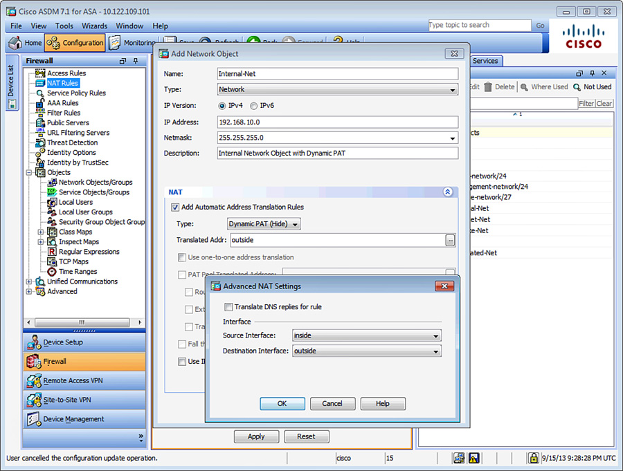
Note
Currently, you can define only one NAT policy within an object.
Similarly, navigate to Configuration > Firewall > NAT Rules and choose Add > Add “Network Object” NAT Rule to define the second policy. As shown in Figure 10-9, a host object called Internal-Web is being added as 192.168.10.10. The NAT type chosen is Static and 209.165.200.240 is specified as the translated address.

Note
The security appliance in version 8.3 and later supports one-to-many mapping. This allows one internal host to have more than one mapped address. It is a useful feature if you want the host to be reachable via multiple global addresses.
If you prefer to use the CLI, the corresponding configuration of Figure 10-8 and Figure 10-9 is shown in Example 10-2.
Example 10-2 Example of Auto NAT
Chicago(config)# object network Internal-Net
Chicago(config-network-object)# subnet 192.168.10.0 255.255.255.0
Chicago(config-network-object)# description Internal Network Object with Dynamic PAT
Chicago(config-network-object)# nat (inside,outside) dynamic interface
Chicago(config-network-object)# exit
Chicago(config)# object network Internal-Web
Chicago(config-network-object)# description Object for Internal Web-Server
Chicago(config-network-object)# nat (inside,outside) static 209.165.200.240
Note
When address translation is turned on, the security appliance does proxy ARP for the configured translated addresses. Proxy ARP is a process in which the security appliance answers ARP requests on behalf of other addresses.
Manual NAT Configuration
Manual NAT is required when you need to define policies involving destination addresses, such as policy-based or identity NAT-based address translations. You can define very specific translation policies that hosts need to communicate with each other. This mode can also be used when you need to translate both the source and destination addresses of traffic flowing from one entity to another entity.
Available Manual NAT Settings
Navigate to Configuration > Firewall > NAT Rules and choose either Add > Add NAT Rule Before “Network Object” NAT Rules or Add >Add NAT Rule After “Network Object” NAT Rules. The NAT rules are processed from the top down, where Manual NAT before Auto NAT is processed first, then the rules within Auto NAT, and then Manual NAT after Auto NAT. In most cases, the Manual NAT rules are defined before Auto NAT. After you choose the Manual NAT option, an Add NAT Rule dialog box opens. You can specify the following attributes in the Match Criteria: Original Packet area:
![]() Source Interface: The name of the interface where a source host or a source subnet resides.
Source Interface: The name of the interface where a source host or a source subnet resides.
![]() Source Address: The name of the object, containing a host or subnet, that needs address translation.
Source Address: The name of the object, containing a host or subnet, that needs address translation.
![]() Destination Interface: The name of the interface where the destination host or a destination subnet resides.
Destination Interface: The name of the interface where the destination host or a destination subnet resides.
![]() Destination Address: The name of the object, containing a host or subnet, where the traffic is destined to.
Destination Address: The name of the object, containing a host or subnet, where the traffic is destined to.
![]() Service: The name of the object containing the real service.
Service: The name of the object containing the real service.
You can specify the following attributes in the Action: Translated Packet area of the Add NAT Rule dialog box:
![]() Source NAT Type: Specify whether you want to define a Static NAT, Static PAT, Dynamic NAT, or Dynamic PAT policy.
Source NAT Type: Specify whether you want to define a Static NAT, Static PAT, Dynamic NAT, or Dynamic PAT policy.
![]() Source Address: The name of the object containing the translated address of the source entity as its member.
Source Address: The name of the object containing the translated address of the source entity as its member.
![]() Destination Address: The name of the object containing the translated address of the destination entity.
Destination Address: The name of the object containing the translated address of the destination entity.
![]() Service: The name of the object containing the translated service.
Service: The name of the object containing the translated service.
In version 8.3 and later, the security appliance adds two unidirectional entries for each static translation, by default. If you have a scenario in which you need to translate outgoing traffic but you don’t want the return traffic to be translated back, you can use the unidirectional parameter at the end of the nat command.
All the other options in the Add NAT Rule dialog box are similar to those discussed in the “Auto NAT Configuration” section.
Manual NAT Configuration Example
As with Auto NAT configuration, the best way to describe the configuration of Manual NAT is to present it in the context of a scenario. For purposes of demonstration, suppose you want to define address translation policies to meet the following requirements:
![]() Translate 192.168.10.0/27 (object = Internal-Net) when traffic is received on the inside interface and destined to 209.165.201.0/24 (object = Internet-Net), located toward the outside interface. The translated source address should be from 209.165.202.128/27 (object = Translated-Net). Make sure that each host receives a unique address that is mapped to an address in the translated subnet.
Translate 192.168.10.0/27 (object = Internal-Net) when traffic is received on the inside interface and destined to 209.165.201.0/24 (object = Internet-Net), located toward the outside interface. The translated source address should be from 209.165.202.128/27 (object = Translated-Net). Make sure that each host receives a unique address that is mapped to an address in the translated subnet.
![]() If traffic is flowing from 192.168.10.0/27 (object = Internal-Net) and destined to 192.168.20.0/27 (object = Remote-Net), then maintain the original source and destination addresses. This is an example of Identity NAT.
If traffic is flowing from 192.168.10.0/27 (object = Internal-Net) and destined to 192.168.20.0/27 (object = Remote-Net), then maintain the original source and destination addresses. This is an example of Identity NAT.
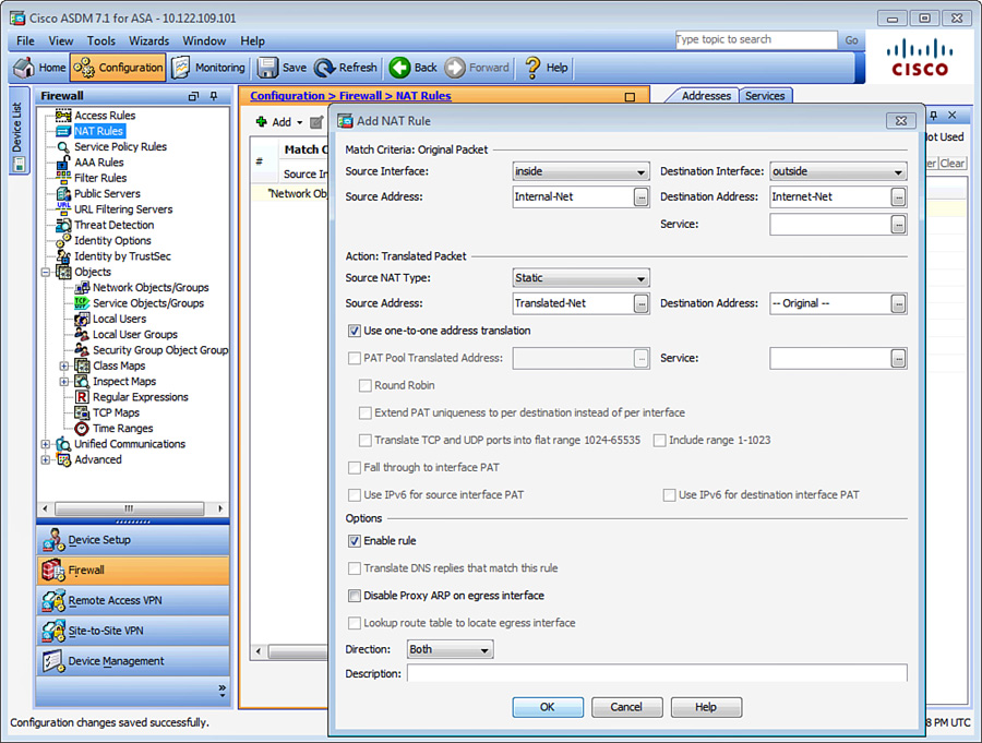
To meet these requirements, you need to define two Manual NAT rules. Navigate to Configuration > Firewall > NAT Rules and choose Add > Add NAT Rule Before “Network Object” NAT Rules to define the first policy. As shown in Figure 10-10, the source interface is set to inside and the destination interface is set to outside. The source address is the Internal-Net object, and the destination address is the Internet-Net object. The source NAT type is set to static, with the Use One-to-One Address Translation option checked. The translated source address is the Translated-Net object.
Similarly, navigate to Configuration > Firewall > NAT Rules and choose Add > Add NAT Rule Before “Network Object” NAT Rules to define the second policy. As shown in Figure 10-11, the source interface is set to inside and the destination address is set to outside. The original source address is the Internal-Net object, and the original destination address is the Remote-Net object. The source NAT type is set to static. The translated source address is also Internal-Net, and the translated destination address is also Remote-Net.

If you prefer to use the CLI, the corresponding configuration of Figure 10-10 and Figure 10-11 is shown in Example 10-3.
Example 10-3 Example of Manual NAT
Chicago(config)# object network Internal-Net
Chicago(config-network-object)# subnet 192.168.10.0 255.255.255.224
Chicago(config-network-object)# object network Internet-Net
Chicago(config-network-object)# subnet 209.165.201.0 255.255.255.0
Chicago(config-network-object)# object network Translated-Net
Chicago(config-network-object)# subnet 209.165.202.128 255.255.255.224
Chicago(config-network-object)# object network Remote-Net
Chicago(config-network-object)# subnet 192.168.20.0 255.255.255.224
Chicago(config-network-object)# exit
Chicago(config)# nat (inside,outside) source static Internal-Net
Translated-Net destination static Internet-Net Internet-Net
Chicago(config)# nat (inside,outside) source static Internal-Net
Internal-Net destination static Remote-Net Remote-Net no-proxy-arp
Integrating ACLs and NAT
Cisco ASA integrates the two core features, ACLs and NAT, to provide a complete security framework. This way, the real IP address of an inside host is hidden from the untrusted hosts/networks while appropriate traffic filtering policies are applied. However, depending on the version of software you are running, the behavior can be different.
Pre-8.3 Behavior for NAT and ACL Integration
When the NAT and ACL are leveraged to protect a host (or a subnet), the ACL is typically applied to the outside interface in the inbound direction. In the pre-8.3 versions, the translated address of the host is used to allow or deny traffic that is destined to it. Figure 10-12 shows an example in which both features are implemented on a security appliance.
A host on the public network (209.165.201.1) establishes a new connection by sending a packet to an inside web server. The security appliance handles the packet in the following sequence:
1. The packet arrives at the outside interface of the security appliance with a source address of 209.165.201.1 and a destination address of 209.165.200.227. Cisco ASA checks the inbound ACL to make sure that the host is allowed to communicate with 209.165.200.227 (the translated address).
2. If the packet is permitted to pass through, the security appliance sends the packet to the NAT engine to determine whether the addresses need to be translated. The destination address is changed to 192.168.10.10.
3. The security appliance creates a connection entry and forwards the packet to the egress (inside) interface after evaluating it against the outbound ACL on the inside interface.
4. The web server replies to Host A, using its source IP address of 192.168.10.10.
5. The packet is forwarded to the NAT engine, which changes the source IP address to 209.165.200.227.
6. The security appliance sends the packet to Host A.
Example 10-4 shows a scenario where the source address of a web server is being changed from 192.168.10.10 to 209.165.200.227. The inbound ACL on the outside interface allows traffic destined to the translated address (209.165.200.227) on port 80.
Example 10-4 Example of NAT and ACL Integration in Pre-8.3 Software
Chicago(config)# static (inside,outside) 209.165.200.227 192.168.10.10 netmask 255.255.255.255
Chicago(config)# access-list inbound_traffic_on_outside permit tcp any host 209.165.200.240 eq www
Chicago(config)# access-group inbound_traffic_on_outside in interface outside
Behavior of NAT and ACL Integration in Version 8.3 and Later
In version 8.3 and later, the real (or nontranslated) address of the host is used to allow or deny traffic that is destined to it. This is a big architectural change and simplifies the deployment so that customers can always reference the same IP address (or the object name) throughout the configuration without needing to know the translated address. Referring again to Figure 10-12, where a host on the public network (209.165.201.1) tries to establish a new connection by sending a packet to an inside web server, the security appliance handles the packet in the following sequence:
1. The packet arrives at the outside interface of the security appliance with a source address of 209.165.201.1 and a destination address of 209.165.200.227. Cisco ASA checks the inbound ACL to make sure that the host is allowed to communicate with the real address of 192.168.10.10.
2. If the packet is permitted to pass through, the security appliance sends the packet to the NAT engine to determine whether the addresses need to be translated. The destination address is changed to 192.168.10.10.
3. The security appliance creates a connection entry and forwards the packet to the egress (inside) interface after evaluating it against the outbound ACL on the inside interface.
4. The web server replies to Host A, using its source IP address of 192.168.10.10.
5. The packet is forwarded to the NAT engine, which changes the source IP address to 209.165.200.227.
6. The security appliance sends the packet to Host A.
Example 10-5 shows a scenario where the source address of a web server is being changed from 192.168.10.10 to 209.165.200.227. The inbound ACL on the outside interface allows traffic destined to the real address (192.168.10.10) on port 80.
Example 10-5 Example of NAT and ACL Integration in Version 8.3 and Later Software
Chicago(config)# object network Inside-Web
Chicago(config-network-object)# host 192.168.10.10
Chicago(config-network-object)# object network Translated-Web
Chicago(config-network-object)# host 209.165.200.227
Chicago(config-network-object)# object network Inside-Web
Chicago(config-network-object)# nat (inside,outside) static
Translated-Web
Chicago(config-network-object)# exit
Chicago(config)# access-list inbound_traffic_on_outside extended
permit tcp any host 192.168.10.10 eq www
Chicago(config)# access-group inbound_traffic_on_outside in interface
outside
Configuration Use Cases
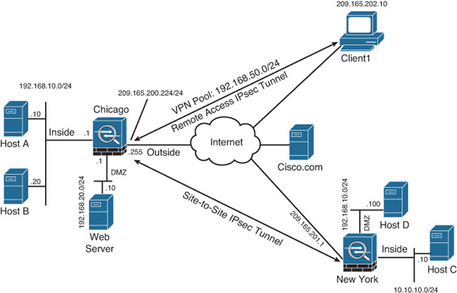
As mentioned earlier, the address translation functionality in Cisco ASA has gone through a major architectural change. This section provides some common use cases for address translation in both the pre-8.3 versions and the 8.3 and later versions. Figure 10-13, used throughout this section, shows two types of VPN connections: a site-to-site tunnel between Chicago and New York, and a VPN client with a remote-access IPsec tunnel that is terminated on the Chicago security appliance. The Chicago security appliance assigns an address from 192.168.50.0/24 subnet to the remote-access VPN clients. The inside network of Chicago has two hosts (Host A and Host B), a DMZ network with a web-server and the outside interface that provides Internet connectivity. The inside network of the New York security appliance contains Host C, while the DMZ network contains Host D. Unfortunately, the DMZ network of New York overlaps with the inside network of Chicago.
The use cases in this section are not built on top of another. They are independent and are intended to show the configuration changes prior to version 8.3 versus the configuration changes in version 8.3 and later. Treat them as individual use cases that are not linked to each other.
Use Case 1: Dynamic PAT for Inside Network with Static NAT for a DMZ Web Server
The goal of this use case is to statically translate the IP address of a web server that is located on the DMZ network of the Chicago security appliance. You also want to dynamically translate the hosts on the inside network using the outside interface’s IP address (209.165.200.225). The translated address of the web server should be 209.165.200.230. Follow these steps to configure this use case in ASDM:
1. Navigate to Configuration > Firewall > NAT Rules and choose Add > Add “Network Object” NAT Rule to define the Inside-Net object for dynamic PAT.
2. Configure the attributes in the Add Network Object dialog box as follows:
![]() Name: Inside-Net
Name: Inside-Net
![]() Type: Network
Type: Network
![]() IP Version: IPv4
IP Version: IPv4
![]() IP Address: 192.168.10.0
IP Address: 192.168.10.0
![]() Netmask: 255.255.255.0
Netmask: 255.255.255.0
![]() Add Automatic Address Translation Rules: Checked
Add Automatic Address Translation Rules: Checked
![]() Type: Dynamic PAT (Hide)
Type: Dynamic PAT (Hide)
![]() Translated Addr: outside
Translated Addr: outside
Click Advanced to open the Advanced NAT Settings dialog box, and configure the attributes in the Interface area as follows:
![]() Source Interface: inside
Source Interface: inside
![]() Destination Interface: outside
Destination Interface: outside
3. Click OK twice in a row to close both dialog boxes.
4. Navigate to Configuration > Firewall > NAT Rules and choose Add > Add “Network Object” NAT Rule to define the Inside-Web object for static NAT.
5. Configure the attributes as follows:
![]() Name: Inside-Web
Name: Inside-Web
![]() Type: Host
Type: Host
![]() IP Version: IPv4
IP Version: IPv4
![]() Add Automatic Address Translation Rules: Checked
Add Automatic Address Translation Rules: Checked
![]() Type: Static
Type: Static
![]() Translated Addr: 209.165.200.230
Translated Addr: 209.165.200.230
Click Advanced to open the Advanced NAT Settings dialog box, and configure the attributes in the Interface area as follows:
![]() Source Interface: DMZ
Source Interface: DMZ
![]() Destination Interface: outside.
Destination Interface: outside.
6. Click OK twice in a row to close both dialog boxes.
Example 10-6 shows the identical CLI configuration of a security appliance running version 8.3 or later.
Example 10-6 Configuration of Use Case 1 in Version 8.3 and Later Software
Chicago(config)# object network Inside-Net
Chicago(config-network-object)# subnet 192.168.10.0 255.255.255.0
Chicago(config-network-object)# nat (inside,outside) dynamic interface
Chicago(config-network-object)# object network Inside-Web
Chicago(config-network-object)# host 192.168.20.10
Chicago(config-network-object)# nat (DMZ,outside) static 209.165.200.230
Example 10-7 shows the identical CLI configuration of a security appliance running a pre-8.3 version.
Example 10-7 Configuration of Use Case 1 in Pre-8.3 Version of Software
Chicago(config)# static (DMZ,outside) 209.165.200.230 192.168.20.10
netmask 255.255.255.255
Chicago(config)# nat (inside) 1 192.168.10.0 255.255.255.0
Chicago(config)# global (outside) 1 interface
Use Case 2: Static PAT for a Web Server Located on the DMZ Network
The goal of this use case is to statically translate the IP address of a web server that is located on the DMZ network of the Chicago security appliance. In some cases, a dedicated global IP address is not available to assign to the DMZ hosts. Consequently, use of static PAT leveraging the outside interface’s IP address is helpful to translate the web server traffic on TCP port 80. Follow these steps to configure this use case in ASDM:
1. Navigate to Configuration > Firewall > NAT Rules and choose Add > Add “Network Object” NAT Rule to define the Inside-Web object for static NAT.
2. Configure the attributes in the Add Network Object dialog box as follows:
![]() Name: Inside-Web
Name: Inside-Web
![]() Type: Host
Type: Host
![]() IP Version: IPv4
IP Version: IPv4
![]() IP Address: 192.168.20.10
IP Address: 192.168.20.10
![]() Add Automatic Address Translation Rules: Selected
Add Automatic Address Translation Rules: Selected
![]() Type: Static
Type: Static
![]() Translated Addr: outside
Translated Addr: outside
Click Advanced to open the Advanced NAT Settings dialog box, and configure the attributes in the Interface and Service areas as follows:
![]() Source Interface: DMZ
Source Interface: DMZ
![]() Destination Interface: outside
Destination Interface: outside
![]() Protocol: tcp
Protocol: tcp
![]() Real Port: www
Real Port: www
![]() Mapped Port: www
Mapped Port: www
3. Click OK twice in a row to close both dialog boxes.
Example 10-8 shows the identical CLI configuration of a security appliance running version 8.3 or later.
Example 10-8 Configuration of Use Case 2 in Version 8.3 and Later Software
Chicago(config)# object network Inside-Web
Chicago(config-network-object)# host 192.168.20.10
Chicago(config-network-object)# nat (DMZ,outside) static interface
service tcp www www
Example 10-9 shows the identical CLI configuration of a security appliance running a pre-8.3 version.
Example 10-9 Configuration of Use Case 2 in Pre-8.3 Version of Software
Chicago(config)# static (DMZ,outside) tcp interface 80 192.168.20.10
80 netmask 255.255.255.255
Chicago(config)#
Use Case 3: Static NAT for Overlapping Subnets Using Twice NAT
As shown in Figure 10-13, the DMZ network of New York overlaps with the inside network of Chicago. The goal of this use case is to translate traffic from the inside network of Chicago to the DMZ network on New York. Consequently, you must leverage Manual NAT. The DMZ network of New York appears as 192.168.100.0 for the hosts on the inside network of Chicago. The inside network of Chicago appears as 10.10.100.0 for the hosts on the DMZ network of New York. This use case assumes that you have the following four objects defined:
![]() Chicago-Real containing 192.168.10.0 as its member
Chicago-Real containing 192.168.10.0 as its member
![]() Chicago-Mapped containing 10.10.100.0 as its member
Chicago-Mapped containing 10.10.100.0 as its member
![]() NewYork-Real containing 192.168.10.0 as its member
NewYork-Real containing 192.168.10.0 as its member
![]() NewYork-Mapped containing 192.168.100.0 as its member
NewYork-Mapped containing 192.168.100.0 as its member
Follow these steps to configure this use case in ASDM:
1. Navigate to Configuration > Firewall > NAT Rules and choose Add > Add NAT Rule Before “Network Object” NAT Rules to define the policy.
2. In the Add NAT Rule dialog box that opens, configure the following attributes in the Match Criteria: Original Packet area:
![]() Source Interface: inside
Source Interface: inside
![]() Destination Interface: outside
Destination Interface: outside
![]() Source Address: Chicago-Real
Source Address: Chicago-Real
![]() Destination Address: NewYork-Mapped
Destination Address: NewYork-Mapped
Configure the following attributes in the Action: Translated Packet area:
![]() Source NAT Type: Static
Source NAT Type: Static
![]() Source Address: Chicago-Mapped
Source Address: Chicago-Mapped
![]() Destination Address: NewYork-Real
Destination Address: NewYork-Real
Configure the following attributes in the Options area:
![]() Enable Rule: Checked
Enable Rule: Checked
![]() Direction: Both.
Direction: Both.
3. Click OK to close the Add NAT Rule dialog box.
Example 10-10 shows the identical CLI configuration of a security appliance running version 8.3 or later.
Example 10-10 Configuration of Use Case 3 in Version 8.3 and Later Software
Chicago(config)# object network Chicago-Real
Chicago(config-network-object-group)# network-object 192.168.10.0
Chicago(config-network-object-group)# object network Chicago-Mapped
Chicago(config-network-object-group)# network-object 10.10.100.0
Chicago(config-network-object-group)# object network NewYork-Real
Chicago(config-network-object-group)# network-object 19.168.10.0
Chicago(config-network-object-group)# object network NewYork-Mapped
Chicago(config-network-object-group)# network-object 192.168.100.00
Chicago(config-network-object-group)# nat (inside,outside) source
static Chicago-Real Chicago-Mapped destination static NewYork-Mapped
NewYork-Real
Example 10-11 shows the identical CLI configuration of a security appliance running a pre-8.3 version.
Example 10-11 Configuration of Use Case 3 in Pre-8.3 Version of Software
Chicago(config)# access-list Inside-2-Remote permit ip 192.168.10.0
255.255.255.0 192.168.100.0 255.255.255.0
Chicago(config)# access-list Remote-2-Inside permit ip 192.168.10.0
255.255.255.0 10.10.100.0 255.255.255.0
Chicago(config)# static (inside,outside) 10.10.100.0 access-list
Inside-2-Remote
Chicago(config)# static (outside,inside) 192.168.100.0 access-list
Remote-2-Inside
Use Case 4: Identity NAT for Site-to-Site VPN Tunnel
One of the common Manual NAT use cases is to bypass translation for the traffic going from the local subnet to the remote subnet over a site-to-site VPN tunnel. For example, if the Chicago security appliance is configured to do address translation for the traffic going from the inside network to the outside network, you do not want to translate traffic from the inside hosts (192.168.10.0/24) that is going to the remote hosts (10.10.10.0/24). This use case assumes that you have the following two objects defined:
![]() Inside-Real containing 192.168.10.0/24 as its member
Inside-Real containing 192.168.10.0/24 as its member
![]() Remote-Real containing 10.10.10.0/24 as its member
Remote-Real containing 10.10.10.0/24 as its member
Note
Configuring a site-to-site VPN tunnel is outside the scope of this chapter. See Chapter 19, “Site-to-Site IPsec VPNs,” for a sample configuration with Identity NAT.
Follow these steps to configure this use case in ASDM:
1. Navigate to Configuration > Firewall > Objects > Network Objects/Groups, double-click the existing Inside-Real object to enable dynamic interface PAT.
2. In the Edit Network Object dialog box that opens, configure the following attributes in the NAT area:
![]() Add Automatic Address Translation Rules: Checked
Add Automatic Address Translation Rules: Checked
![]() Type: Dynamic PAT (Hide)
Type: Dynamic PAT (Hide)
![]() Translated Addr: outside
Translated Addr: outside
Click Advanced to open the Advanced NAT Settings dialog box, and configure the attributes in the Interface area as follows:
![]() Source Interface: inside
Source Interface: inside
![]() Destination Interface: outside.
Destination Interface: outside.
3. Click OK twice in a row to close both dialog boxes.
4. Navigate to Configuration > Firewall > NAT Rules > Add > Add NAT Rule Before “Network Object” NAT Rules to define the policy.
5. In the Add NAT Rule dialog box that opens, configure the following attributes in the Match Criteria: Original Packet area:
![]() Source Interface: inside
Source Interface: inside
![]() Destination Interface: outside
Destination Interface: outside
![]() Source Address: Inside-Real
Source Address: Inside-Real
![]() Destination Address: Remote-Real
Destination Address: Remote-Real
Configure the following attributes in the Action: Translated Packet area:
![]() Source NAT Type: Static
Source NAT Type: Static
![]() Source Address: Inside-Real
Source Address: Inside-Real
![]() Destination Address: Remote-Real
Destination Address: Remote-Real
Configure the following attributes in the Options area:
![]() Enable Rule: Checked
Enable Rule: Checked
![]() Direction: Both
Direction: Both
6. Click OK to close the Add NAT Rule dialog box.
Example 10-12 shows the identical CLI configuration of a security appliance running version 8.3 or later.
Example 10-12 Configuration of Use Case 4 in Version 8.3 and Later Software
Chicago(config)# object network Inside-Real
Chicago(config-network-object)# subnet 192.168.10.0 255.255.255.0
Chicago(config-network-object)# nat (inside,outside) dynamic interface
Chicago(config-network-object)# object network Remote-Real
Chicago(config-network-object)# subnet 10.10.10.0 255.255.255.0
Chicago(config-network-object)# exit
Chicago(config)# nat (inside,outside) source static Inside-Real
Inside-Real destination static Remote-Real Remote-Real
Example 10-13 shows the identical CLI configuration of a security appliance running a pre-8.3 version.
Example 10-13 Configuration of Use Case 4 in Pre-8.3 Version of Software
Chicago(config)# nat (inside) 1 192.168.10.0 255.255.255.0
Chicago(config)# global (outside) 1 interface
Chicago(config)# access-list Bypass-NAT permit ip 192.168.10.0
255.255.255.0 10.10.10.0 255.255.255.0
Chicago(config)# nat (inside) 0 access-list Bypass-NAT
Use Case 5: Dynamic PAT for Remote-Access VPN Clients
As shown in Figure 10-13, the Chicago security appliance offers remote-access services for its mobile users. For enhanced security, split tunneling is not allowed and all Internet-bound traffic must flow through the firewall. During the VPN tunnel negotiations, the security appliance assigns an IP address to the VPN client from the VPN pool. Suppose the VPN client (Client1) wants to send traffic to Cisco.com. The encrypted traffic from the client goes to the security appliance. After decrypting the traffic, the security appliance performs address translation to change the assigned address (from 192.168.50.0/24) to a routable address and resends packets out to the Internet to Cisco.com. You also want to allow remote-access VPN clients to communicate with the inside network. For that traffic you do not want to do address translation. However, all the other traffic from the inside network to the Internet needs to be translated. This use case assumes that you have the following two objects defined:
![]() Inside-Real containing 192.168.10.0/24 as its member
Inside-Real containing 192.168.10.0/24 as its member
![]() VPN-Real containing 192.168.50.0/24 as its member
VPN-Real containing 192.168.50.0/24 as its member
Note
Configuring remote-access VPN tunnels is outside the scope of this chapter. See Chapter 20, “IPsec Remote-Access VPNs,” for a sample configuration of this use case.
Follow these steps to configure this use case in ASDM:
1. Navigate to Configuration > Firewall > Objects > Network Objects/Groups, double-click the existing Inside-Real object to enable dynamic interface PAT.
2. In the Edit Network Object dialog box that opens, configure the following attributes in the NAT area:
![]() Add Automatic Address Translation Rules: Checked
Add Automatic Address Translation Rules: Checked
![]() Type: Dynamic PAT (Hide)
Type: Dynamic PAT (Hide)
![]() Translated Addr: outside
Translated Addr: outside
Click Advanced to open the Advanced NAT Settings dialog box, and configure the attributes in the Interface area as follows:
![]() Source Interface: inside
Source Interface: inside
![]() Destination Interface: outside.
Destination Interface: outside.
3. Click OK twice in a row to close both dialog boxes.
4. Navigate to Configuration > Firewall > Objects > Network Objects/Groups, double-click the existing VPN-Real object to enable dynamic interface PAT.
5. In the Edit Network Object dialog box that opens, configure the following attributes in the NAT area:
![]() Add Automatic Address Translation Rules: Checked
Add Automatic Address Translation Rules: Checked
![]() Type: Dynamic PAT (Hide)
Type: Dynamic PAT (Hide)
![]() Translated Addr: outside
Translated Addr: outside
Click Advanced and configure the attributes in the Interface area as follows:
![]() Source Interface: outside
Source Interface: outside
![]() Destination Interface: outside
Destination Interface: outside
6. Click OK twice in a row to close both dialog boxes.
7. Navigate to Configuration > Firewall > NAT Rules > Add > Add NAT Rule Before “Network Object” NAT Rules to define the policy.
8. In the Add NAT Rule dialog box that opens, configure the following attributes in the Match Criteria: Original Packet area:
![]() Source Interface: inside
Source Interface: inside
![]() Destination Interface: outside
Destination Interface: outside
![]() Source Address: Inside-Real
Source Address: Inside-Real
![]() Destination Address: VPN-Real
Destination Address: VPN-Real
Configure the following attributes in the Action: Translated Packet area:
![]() Source Address: Inside-Real
Source Address: Inside-Real
![]() Destination Address: VPN-Real
Destination Address: VPN-Real
Configure the following attributes in the Options area:
![]() Enable Rule: Checked
Enable Rule: Checked
![]() Direction: Both
Direction: Both
9. Click OK to close the Add NAT Rule dialog box.
Example 10-14 shows the identical CLI configuration of a security appliance running version 8.3 or later.
Example 10-14 Configuration of Use Case 5 in Version 8.3 and Later Software
Chicago(config)# object network Inside-Real
Chicago(config-network-object)# subnet 192.168.10.0 255.255.255.0
Chicago(config-network-object)# nat (inside,outside) dynamic interface
Chicago(config-network-object)# object network VPN-Real
Chicago(config-network-object)# subnet 192.168.50.0 255.255.255.0
Chicago(config-network-object)# nat (outside,outside) dynamic interface
Chicago(config-network-object)# exit
Chicago(config)# nat (inside,outside) source static Inside-Real
Inside-Real destination static VPN-Real VPN-Real
Example 10-15 shows the identical CLI configuration of a security appliance running a pre-8.3 version.
Example 10-15 Configuration of Use Case 5 in Pre-8.3 Version of Software
Chicago(config)# nat (inside) 1 192.168.10.0 255.255.255.0
Chicago(config)# global (outside) 1 interface
Chicago(config)# nat (outside) 1 192.168.50.0 255.255.255.0
Chicago(config)# global (outside) 1 interface
Chicago(config)# access-list Bypass-NAT permit ip 192.168.10.0
255.255.255.0 192.168.50.0 255.255.255.0
Chicago(config)# nat (inside) 0 access-list Bypass-NAT
Note
For traffic hair-pinning, enable intra-traffic traffic forwarding using the same-security-traffic permit intra-interface command.
DNS Doctoring
In many network deployments, the DNS servers and DNS clients are set up for address translation but are located on different subnets through the security appliance. This is illustrated in Figure 10-14. The web server (www.securemeinc.org) and the web clients are located on the inside network, whereas the DNS server is on the outside network. The real IP address of the web server is 192.168.10.10 and the translated public address is 209.265.200.227.
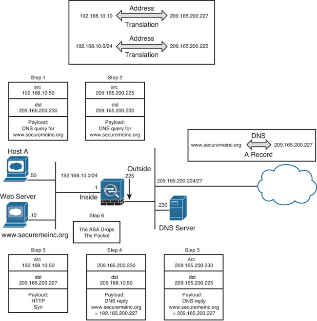
The problem arises when a web client (Host A) tries to access the web server using the server’s hostname. In this scenario, the following sequence of events occurs:
1. Host A sends a request to the DNS server, inquiring about the IP address of the web server.
2. The source IP address is translated to 209.165.200.225, using dynamic PAT or any other form of address translation.
3. The DNS server replies with the external IP address of the web server (209.165.200.227) as a type A DNS record.
4. The security appliance translates the destination IP address to 192.168.10.50 (Host A’s IP address).
5. The client, not knowing that the web server is on the same subnet, tries to connect to the public IP address.
6. The security appliance drops the packets because the server resides on the inside interface and the packets are destined for the public IP address.
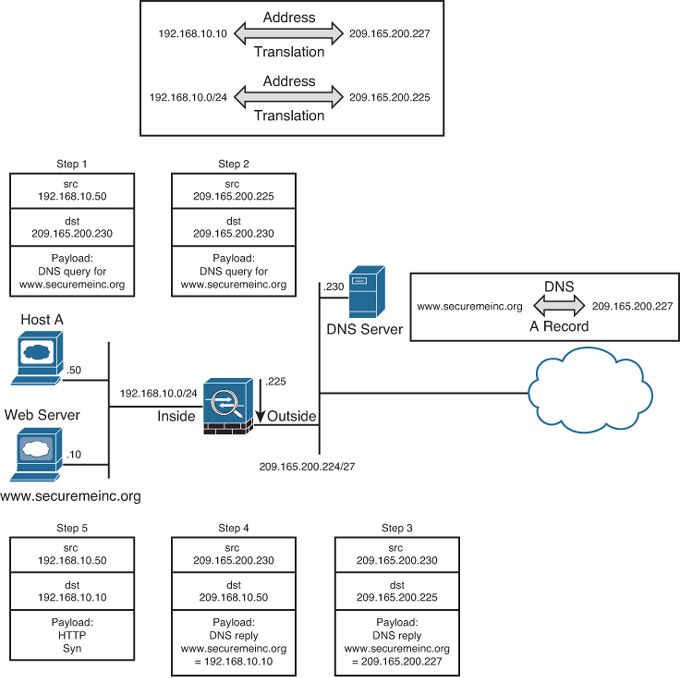
The DNS doctoring feature of the security appliance inspects the data payload of the DNS replies and changes the type A DNS record (IP address sent by the DNS server) to an address specified in the NAT configuration. In Figure 10-15, the security appliance modifies the IP address in the payload from 209.165.200.227 to 192.168.10.10 (Step 4) before forwarding the DNS reply to the client. The client uses the real address to connect to the web server.
DNS doctoring is configured within the NAT definition of an Auto NAT object or within the Manual NAT entry definition.
![]() For Manual NAT entries: Select the Translate DNS Replies That Match This Rule check box in the Options area of the Manual NAT Rule dialog box, as shown in Figure 10-11 earlier in the chapter.
For Manual NAT entries: Select the Translate DNS Replies That Match This Rule check box in the Options area of the Manual NAT Rule dialog box, as shown in Figure 10-11 earlier in the chapter.
![]() For Auto NAT entries: Select the Translate DNS replies for rule check box under the Advanced NAT properties of an object, as shown in Figure 10-9 earlier in the chapter.
For Auto NAT entries: Select the Translate DNS replies for rule check box under the Advanced NAT properties of an object, as shown in Figure 10-9 earlier in the chapter.
If you prefer to use the CLI, add the dns keyword to the end of the nat command that is translating the real IP address of a host. In Example 10-16, an Auto NAT entry is set up to translate a real IP address from 192.168.10.20 to a global IP address, 209.165.200.227. The dns keyword is specified to enable DNS doctoring for this server.
Example 10-16 Configuration of DNS Doctoring
Chicago(config)# object network Inside-Web
Chicago(config-network-object)# host 192.168.10.10
Chicago(config-network-object)# nat (inside,outside) static 209.165.200.227 dns
Note
DNS doctoring can be achieved only on NAT entries. You cannot do DNS doctoring for PAT entries.
Monitoring Address Translations
Cisco ASA provides a rich set of show commands to monitor and troubleshoot issues related to address translation. The most important monitoring command is show xlate, which displays the active translations for real (local) address and their mapped (global) IP address. Example 10-17 shows the output of the Use Case 5 address translation configuration and the output of show xlate. The first two entries relate to Manual NAT translation for Identity NAT. The last entry shows an active PAT translation for 192.168.10.10. The security appliance translates the real address to 209.165.200.225 (outside interface’s IP address). The security appliance also shows the maximum number of simultaneous translations (5 in this case) it has performed since the last reboot and the current active translations (3).
Example 10-17 Output of show xlate
Chicago(config)# object network Inside-Real
Chicago(config-network-object)# subnet 192.168.10.0 255.255.255.0
Chicago(config-network-object)# nat (inside,outside) dynamic interface
Chicago(config-network-object)# object network VPN-Real
Chicago(config-network-object)# subnet 192.168.50.0 255.255.255.0
Chicago(config-network-object)# nat (outside,outside) dynamic interface
Chicago(config-network-object)# exit
Chicago(config)# nat (inside,outside) source static Inside-Real
Inside-Real destination static VPN-Real VPN-Real
Chicago(config)# show xlate
3 in use, 5 most used
Flags: D - DNS, e - extended, I - identity, i - dynamic, r - portmap,
s - static, T - twice, N - net-to-net
NAT from inside:192.168.10.0/24 to outside:192.168.10.0/24
flags sIT idle 0:06:48 timeout 0:00:00
NAT from outside:192.168.50.0/24 to inside:192.168.50.0/24
flags sIT idle 0:06:48 timeout 0:00:00
TCP PAT from inside:192.168.10.10/55863 to
outside:209.165.200.225/55863 flags ri idle 0:03:53 timeout 0:00:30
Use a single command, show local-host, to display connection and translation statistics for a host or multiple hosts, as shown in Example 10-18. It displays the network state of each host on the local network. The TCP and UDP flow count counters display the active sessions going through the security appliance from that particular host.
Example 10-18 Output of show local-host
Chicago# show local-host 192.168.10.10
Interface DMZ: 0 active, 0 maximum active, 0 denied
Interface inside: 1 active, 1 maximum active, 0 denied
local host: <192.168.10.10>,
TCP flow count/limit = 1/unlimited
TCP embryonic count to host = 0
TCP intercept watermark = unlimited
UDP flow count/limit = 0/unlimited
Xlate:
TCP PAT from inside:192.168.10.10/55863 to
outside:209.165.200.225/55863 flags ri idle 0:03:40 timeout 0:00:30
Conn:
TCP outside 209.165.200.250:22 inside 192.168.10.10:55863, idle
0:01:40, bytes 1636, flags UFRxIO
Interface outside: 1 active, 1 maximum active, 0 denied
Interface management: 2 active, 3 maximum active, 0 denied
Note
The show local-host all command can be used to see both the management connections to the security appliance and the connections going through the security appliance.
Lastly, use the show nat command to see the output of the Unified NAT table, discussed earlier in the section “NAT Order of Operation for Version 8.3 and Later.” This table shows all the static and dynamic policies in three sections and the real-time hit counts of those policies. If you want to see the expanded view of the defined objects and their values, use the show nat detail command. In Example 10-19, the output of a show nat detail command is displayed. There are 15 hits to the first Manual NAT policy, and all those packets were untranslated (Identity NAT), while there are 23 hits to the first Auto NAT policy for the traffic coming from the inside network going to the Internet. Much like the hit count for an ACL, the hit count for a NAT rule increments when a connection is built using that translation, not for every packet seen on a connection.
Example 10-19 Output of show nat detail
Chicago# show nat detail
Manual NAT Policies (Section 1)
1 (inside) to (outside) source static Inside-Real Inside-Real
destination static VPN-Real VPN-Real
translate_hits = 15, untranslate_hits = 15
Source - Origin: 192.168.10.0/24, Translated: 192.168.10.0/24
Destination - Origin: 192.168.50.0/24, Translated: 192.168.50.0/24
Auto NAT Policies (Section 2)
1 (inside) to (outside) source dynamic Inside-Real interface
translate_hits = 23, untranslate_hits = 0
Source - Origin: 192.168.10.0/24, Translated: 209.165.200.225/27
2 (outside) to (outside) source dynamic VPN-Real interface
translate_hits = 0, untranslate_hits = 0
Source - Origin: 192.168.50.0/24, Translated: 209.165.200.225/27
Summary
This chapter explained one of the core features of a traditional security firewall: Network Address Translation. It discussed the different NAT types that are available in the security appliance, their behavior in the pre-8.3 versions and in the 8.3 and later versions, and a few additional security protections included within NAT. This chapter also demonstrated how a security appliance can be configured to support address translation via ASDM as well as through the CLI. It examined five common use cases related to NAT and their configuration in the pre-8.3 versions and in the 8.3 and later versions. The last section of this chapter discussed a number of show commands that you can use to monitor and troubleshoot the issues related to address translation.