Chapter 12. IP Routing
This chapter covers the following topics:
![]() Configuring and troubleshooting RIP
Configuring and troubleshooting RIP
![]() Configuring and troubleshooting OSPF
Configuring and troubleshooting OSPF
![]() Configuring and troubleshooting EIGRP
Configuring and troubleshooting EIGRP
Network devices use a routing decision to identify which interface and gateway should be used to forward packets for a specific destination. To make this decision, they use dynamic routing protocols or static entries configured on such devices. This chapter covers the different routing capabilities of the Cisco ASA.
The Cisco ASA supports the following routing mechanisms and protocols:
![]() Static routes
Static routes
![]() Routing Information Protocol (RIP)
Routing Information Protocol (RIP)
![]() Open Shortest Path First (OSPF)
Open Shortest Path First (OSPF)
![]() Enhanced Interior Gateway Routing Protocol (EIGRP)
Enhanced Interior Gateway Routing Protocol (EIGRP)
Configuring Static Routes
Deployment and configuration of static routes is appropriate when the Cisco ASA cannot dynamically build a route to a specific destination. This may be because the device to which the Cisco ASA is forwarding the packets does not support a compatible dynamic routing protocol. Another example might be when the network topology is small and uncomplicated. Static routes are easy to configure. However, they do not scale well in large environments. A dynamic routing protocol, such as RIP, OSPF, or EIGRP, must be considered if the network is fairly large and complex.
It is strongly recommended that you have a complete understanding of your network topology before configuring routing in your Cisco ASA. A best practice is to have a network topology diagram on hand to refer to when configuring your Cisco ASA.
Figure 12-1 shows a simple static route topology that includes a Cisco ASA with two interfaces configured (outside and inside).

The goal in Figure 12-1 is to configure a static default route for the Cisco ASA to be able to forward packets to the Internet through the Internet router. Additionally, the Cisco ASA must be configured with a static route on the inside interface that can reach the 10.10.2.0/24 network.
To complete these tasks with the Cisco Adaptive Security Device Manager (ASDM), complete the following steps:
1. Launch ASDM and log in to the Cisco ASA.
2. Navigate to Configuration > Device Setup > Routing > Static Routes.
3. Click Add.
4. The dialog box illustrated in Figure 12-2 is shown. First add a default route to the Internet router (209.165.201.2), as shown in Figure 12-2.
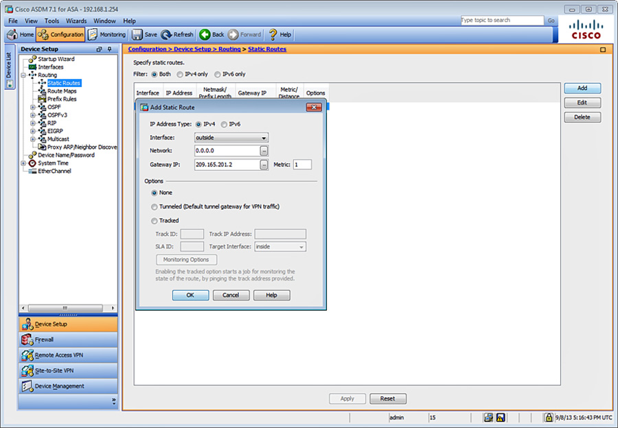
5. Choose the outside interface in the Interface field.
6. Enter 0.0.0.0 in the Network field.
7. The IP address of the Internet router is 209.165.201.2. Enter 209.165.201.2 in the Gateway IP field.
8. Leave all other options with their default values and click OK.
Note
The Metric field specifies the administrative distance of the route. The default is 1 if a metric is not specified. The Tunneled option classifies the route as the default tunnel gateway used for VPN traffic. This option is covered in more detail in Chapter 22, “Clientless Remote-Access SSL VPNs.” One important note to remember is that this option is used only for a default route. You can configure only one tunneled route per device. The Tracked option is discussed later in this chapter.
9. Add a static route so the Cisco ASA can reach the 10.10.2.0/24 network. Navigate to Configuration > Device Setup > Routing > Static Routes and click Add to add a new static route, as shown in Figure 12-3.
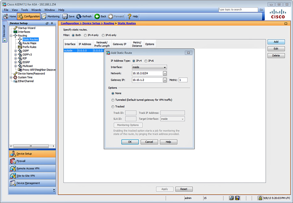
10. Choose the inside interface in the Interface field.
11. Enter 10.10.2.0/24 in the Network field.
12. The IP address of the inside router is 10.10.1.2. Enter 10.10.1.2 in the Gateway IP field.
13. Leave all other options with their default values and click OK.
14. Click Apply to apply the changes to the configuration.
15. Click Save to save the configuration on the Cisco ASA.
Alternatively, you can use the command-line interface (CLI) route command to add a static route.
The following example shows how the static route is added on the Cisco ASA:
route outside 10.10.2.0 255.255.255.0 209.165.201.2 1
The following example shows how the default route is added on the Cisco ASA:
route outside 0.0.0.0 0.0.0.0 209.165.201.2 1
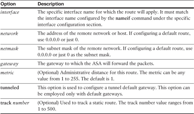
You configure static routes by using the route command, as shown in the following syntax:
route interface network netmask gateway metric [tunneled] [track number]
Table 12-1 details the options available within the route command.
A feature was added in Cisco ASA Software version 7.2(1) to allow for monitoring of the availability of a static route and installing a backup route if the primary route should fail. The following section provides more details about the tracking option.
Static Route Monitoring
Initially, there was no mechanism for determining whether a route was “up” or “down” on the Cisco ASA. Static routes stayed in the routing table even if the next-hop gateway became unavailable, and they were removed from the routing table only if the corresponding interface went down. The ability to track the availability of a static route and install a backup route was added in Cisco ASA Software version 7.2(1).
The security appliance accomplishes this by associating a static route with a monitoring target that you define. It uses Internet Control Message Protocol (ICMP) ECHO requests to monitor the target. If an ECHO reply is not received within a specified time period, the object is considered unreachable and the associated route is removed from the routing table. A previously configured backup route is used in place of the removed route.
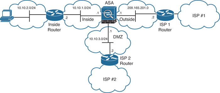
The network topology illustrated in Figure 12-4 shows a Cisco ASA configured with three interfaces (inside, outside, and DMZ). The goal in this example is to configure the route monitoring feature to track the default route through the Internet service provider (ISP) number 1 connection. If the connection to ISP number 1 fails, the Cisco ASA should use the connection to ISP number 2 off the DMZ interface.
In ASDM, configure route monitoring as follows to achieve the goal in this example:
1. Navigate to Configuration > Device Setup > Routing > Static Routes. Click Add to add a new static route or click Edit to edit an existing route.
2. The dialog box illustrated in Figure 12-5 is displayed. The default route is edited. To enable route monitoring, click the Tracked option, as shown.

3. The Track ID is a unique identifier for the route tracking process. For this example, enter the unique but arbitrary number 1.
4. The Track IP Address defines the target host being tracked. Usually, the IP address of the next-hop gateway for the route is defined here; however, this could be any host in the network off the interface where this route is configured. Enter the upstream IP address residing in ISP 1 network, 209.165.201.2.
5. The SLA ID is a unique identifier for the SLA monitoring process. The SLA process is used to monitor the availability of the IP address defined in the Track IP Address field. This allows the Cisco ASA to use a preconfigured backup route. For this example, enter the unique but arbitrary value 123.
6. The Target Interface is the interface where the selected host resides, which is the outside interface in this example.
(Optional) You can customize several monitoring options by clicking the Monitor Options button. The Route Monitoring Options dialog box that opens is shown in Figure 12-6.
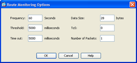
7. Specify how often the Cisco ASA should check that the tracking target is reachable by using the Frequency field. The default value of 60 seconds is used in the example shown in Figure 12-6; however, you can configure this value from 1 to 604,800 seconds.
8. The Threshold field enables you to specify a lifetime (in milliseconds) for this route. The default value is used (5000 milliseconds).
9. The Timeout field enables you to specify the amount of time the Cisco ASA waits for a response from the tracked host. The default value is used (5000 milliseconds); however, valid values are from 0 to 604,800,000 milliseconds.
10. The Cisco ASA uses ICMP echo request packets to verify that the tracked host is alive. The Data Size field specifies the size of data payload to use in such ICMP echo request packets. The default value of 28 bytes is used; however, the value can be any number from 0 to 16384.
11. The ToS field enables you to specify a value for the type of service (ToS) byte in the IP header of the echo request. The default value of 0 is used; however, you can specify any number from 0 to 255.
12. Specify the number of ICMP echo requests to be sent for each test by using the Number of Packets field. The default value is used (1 packet); however, this can be any number from 1 to 100. Be aware that specifying several packets per test may have a direct impact on network performance.
13. Click OK in the Route Monitoring Options dialog box.
14. Click OK in the Edit Static Route box.
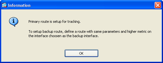
15. The dialog box shown in Figure 12-7 is displayed. This is an informational message that reminds the administrator that the primary route is set up for tracking. Subsequently, you should define another route (the backup route) with the same parameters but with a higher metric value on the interface chosen as the backup interface (in this case, the DMZ interface).
Example 12-1 shows the CLI commands sent to the Cisco ASA from ASDM.
Example 12-1 Static Routing Commands Sent by ASDM
! The following are the three static routes that were
! previously configured. The track option is used on the first default route.
route outside 0.0.0.0 0.0.0.0 209.165.201.2 255 track 1
route dmz 0.0.0.0 0.0.0.0 10.10.3.2 5
route inside 10.10.2.0 255.255.255.0 10.10.1.2 1
!
! The sla monitor command is shown with the 123 identifier.
! The ICMP protocol is used to test the ISP 1 router.
! If this route fails the default route on the dmz is used.
sla monitor 123
type echo protocol ipIcmpEcho 209.165.201.2 interface dmz
sla monitor schedule 123 life forever start-time now
!
! The track command is used with 1 as the identifier. The sla (123) is associated to this command.
track 1 rtr 123 reachability
Note
Additional information about IP SLA and route tracking is covered in Chapter 16, “High Availability.”
Displaying the Routing Table
To display the Cisco ASA’s routing table in ASDM, navigate to Monitoring > Routing > Routes. Alternatively, in the CLI you can use the show route command in the Cisco ASA’s routing table and verify the configuration. Example 12-2 shows the output of the show route command after the previously mentioned static route statements have been configured.
Example 12-2 Displaying the Routing Table via the CLI
NewYork# show route
Codes: C - connected, S - static, I - IGRP, R - RIP, M - mobile, B - BGP
D - EIGRP, EX - EIGRP external, O - OSPF, IA - OSPF inter area
N1 - OSPF NSSA external type 1, N2 - OSPF NSSA external type 2
E1 - OSPF external type 1, E2 - OSPF external type 2, E - EGP
i - IS-IS, L1 - IS-IS level-1, L2 - IS-IS level-2, ia - IS-IS inter area
* - candidate default, U - per-user static route, o - ODR
P - periodic downloaded static route
Gateway of last resort is 10.10.3.2 to network 0.0.0.0
C 172.18.104.128 255.255.255.192 is directly connected, management
C 209.165.201.0 255.255.255.224 is directly connected, outside
C 10.10.1.0 255.255.255.0 is directly connected, inside
S 10.10.2.0 255.255.255.0 [1/0] via 10.10.1.2, inside
C 10.10.3.0 255.255.255.0 is directly connected, dmz
S* 0.0.0.0 0.0.0.0 [5/0] via 209.165.201.2, outside
The letter S by each route statement indicates that it is a statically configured route entry. The letter C indicates that it is a directly connected route. The first number in the brackets is the administrative distance of the information source; the second number is the metric for the route. Administrative distance is the feature used by routing devices to select the best path when there are two or more different routes to the same destination from two different routing protocols.
Tip
The show route command is useful when troubleshooting any routing problems. It provides not only the gateway’s IP address for each route entry but also the interface that is connected to that gateway. In the case, where multiple static routes exist to a network with different metrics, the Cisco ASA uses the one with the best metric at the time that a connection is created. You can use the timeout floating-conn command to enable the Cisco ASA to close and reestablish a connection when or if a better route becomes available. The default value is 0 (the connection never times out).
The show route command can be used with an interface name to display only the routes going out of the specified interface.
Static routes do not provide a scalable solution for medium and large networks. To achieve better scalability, use dynamic routing protocols. The Cisco ASA supports RIP, OSPF, and EIGRP. The following sections discuss these dynamic routing protocols in more detail.
Note
Dynamic routing protocols are supported when the Cisco ASA is running in multiple-context mode and clustering starting with version 9.0(1). Cisco ASA has the ability to create multiple security contexts (virtual firewalls), as covered in Chapter 14, “Virtualization.”
RIP
RIP is a fairly old Interior Gateway Protocol (IGP), but it is still deployed in many networks. It is typically used in small and homogeneous networks. RIP is a distance-vector routing protocol, and it is defined in RFC 1058, “Routing Information Protocol.” Its second version is defined in RFC 2453, “RIP Version 2.”
RIP uses broadcast or multicast packets—depending on the version—to communicate with its neighbors and exchange routing information. It employs the hop-count methodology to calculate its metric. Hop count is the number of routing devices that the packets forwarded by a router or a Cisco ASA (in this case) traverse. RIP has a limit of 15 hops. A route to a network that is directly connected to the Cisco ASA has a metric of 0. A route with a metric reaching or exceeding 16 is considered unreachable. Two versions of the RIP routing protocol are available (Cisco ASA supports both versions):
![]() RIP version 1 (RIPv1): Does not support classless interdomain routing (CIDR) and variable-length subnet masking (VLSM). VLSM enables routing protocols to define different subnet masks for the same major network. For example, 10.0.0.0 is a Class A network. Its mask is 255.0.0.0. VLSM makes it possible to divide this network into smaller segments (i.e., 10.1.1.0/24, 10.1.2.0/24, etc.). Because RIPv1 does not support VLSM, no subnet mask information is present in its routing updates. To prevent loops, RIP uses various techniques such as:
RIP version 1 (RIPv1): Does not support classless interdomain routing (CIDR) and variable-length subnet masking (VLSM). VLSM enables routing protocols to define different subnet masks for the same major network. For example, 10.0.0.0 is a Class A network. Its mask is 255.0.0.0. VLSM makes it possible to divide this network into smaller segments (i.e., 10.1.1.0/24, 10.1.2.0/24, etc.). Because RIPv1 does not support VLSM, no subnet mask information is present in its routing updates. To prevent loops, RIP uses various techniques such as:
![]() Holddowns
Holddowns
![]() Count-to-infinity
Count-to-infinity
![]() Split horizon
Split horizon
![]() Poison reverse
Poison reverse
![]() RIP version 2 (RIPv2): Supports CIDR and VLSM. RIPv2 also converges faster than its predecessor. It supports peer or neighbor authentication (plain-text or MD5 authentication), which provides additional security. RIPv2 uses multicast for communication between peers, in contrast to RIPv1, which uses broadcast.
RIP version 2 (RIPv2): Supports CIDR and VLSM. RIPv2 also converges faster than its predecessor. It supports peer or neighbor authentication (plain-text or MD5 authentication), which provides additional security. RIPv2 uses multicast for communication between peers, in contrast to RIPv1, which uses broadcast.
Configuring RIP
The configuration of the Cisco ASA is simple, but somewhat limited. Figure 12-8 illustrates the first example topology.
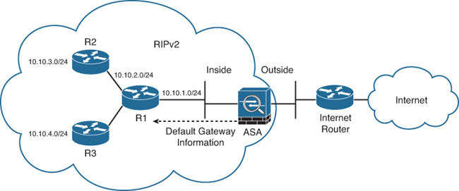
In Figure 12-8, the Cisco ASA is connected to a router (R1) running RIPv2. This router is learning routes from two other routers (R2 and R3). Subsequently, routes to all these networks are being advertised by the router connected to the Cisco ASA. The Cisco ASA is also injecting a default route to the inside router.
To configure RIP for the example topology using ASDM, complete the following steps:
1. Navigate to Configuration > Device Setup > Routing > RIP > Setup and check Enable RIP Routing, as shown in Figure 12-9. When you enable RIP, it is enabled on all interfaces. When you check this check box, the other fields on this page become available.

2. To enable automatic route summarization, check Enable Auto-summarization. This option is enabled by default when you enable RIP in ASDM. You cannot disable automatic summarization for RIPv1.
3. To specify the RIP version used by the Cisco ASA, check Enable RIP Version and then click Version 2, as indicated in the example topology. This setting can be also configured on a per-interface basis in the ASDM interface configuration section.
4. In Figure 12-9, the Cisco ASA generates a route advertisement, so the internal routers use the Cisco ASA as their default gateway. Check the Enable Default Information Originate check box to generate a default route into the RIP routing process.
5. In the Network area, define the network for the RIP routing process, which is the 10.10.1.0 network in this example. Enter 10.10.1.0 in the IP Network to Add field and click Add. The network number specified must not contain any subnet information. There is no limit to the number of networks you can add to the RIP configuration. RIP routing updates are sent and received through only those interfaces on the networks you define in this section.
6. In the Passive Interfaces area, you can check the Global Passive check box to configure the Cisco ASA to listen for RIP routing broadcasts globally on all interfaces and use that information to populate the routing tables, but to not broadcast routing updates. However, for purposes of this example, leave the Global Passive check box unchecked and choose the inside interface as the only passive RIP interface by checking the corresponding check box in the Passive Interfaces table.
7. Click Apply to apply the configuration changes in ASDM.
8. Click Save to save the configuration to the Cisco ASA.
Example 12-3 shows the CLI commands configured in the Cisco ASA by ASDM.
router rip
network 10.0.0.0
passive-interface inside
default-information originate
version 2
no auto-summary
The router rip command enables RIP on the Cisco ASA. The networks specified for the RIP routing process are defined by the network command. Note that in Figure 12-9 the administrator has configured 10.10.1.0; however, the Cisco ASA CLI automatically summarizes this network to 10.0.0.0.
The desired result is for the Cisco ASA to learn the internal routes and advertise default route information. To accomplish this, the default-information originate command is used. The version command specifies what RIP version is used. RIP version 2 is used.
Example 12-4 shows the output of the show route command after learning the routes from R1.
Example 12-4 Output of the show route Command After Learning RIP Routes
NewYork# show route
Codes: C - connected, S - static, I - IGRP, R - RIP, M - mobile, B - BGP
D - EIGRP, EX - EIGRP external, O - OSPF, IA - OSPF inter area
N1 - OSPF NSSA external type 1, N2 - OSPF NSSA external type 2
E1 - OSPF external type 1, E2 - OSPF external type 2, E - EGP
i - IS-IS, L1 - IS-IS level-1, L2 - IS-IS level-2, ia - IS-IS inter area
* - candidate default, U - per-user static route, o - ODR
P - periodic downloaded static route
Gateway of last resort is 209.165.201.2 to network 0.0.0.0
C 172.18.104.128 255.255.255.192 is directly connected, management
C 209.165.201.0 255.255.255.224 is directly connected, outside
C 10.10.1.0 255.255.255.0 is directly connected, inside
R 10.10.2.0 255.255.255.0 [120/1] via 10.10.1.2, 0:00:15, inside
R 10.10.3.0 255.255.255.0 [120/1] via 10.10.1.2, 0:00:15, inside
R 10.10.4.0 255.255.255.0 [120/1] via 10.10.1.2, 0:00:13, inside
S* 0.0.0.0 0.0.0.0 [255/0] via 209.165.201.2, outside
RIP Authentication
RIPv1 does not support authentication. Cisco ASA supports two modes of RIPv2 authentication: plain-text authentication and Message Digest 5 (MD5) authentication.
A best practice is to use MD5 instead of plain-text authentication because MD5 authentication provides a higher level of security.
RIP authentication using MD5 is added in the example topology shown in Figure 12-10.
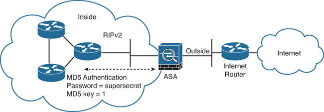
To enable RIP authentication using MD5 for the topology shown in Figure 12-10, complete the following steps:
1. Log in to ASDM and navigate to Configuration > Device Setup > Routing > RIP > Interface.
2. Select the interface where RIP is enabled (inside) and click Edit, which opens the Edit RIP Interface Entry dialog box, as shown in Figure 12-11.
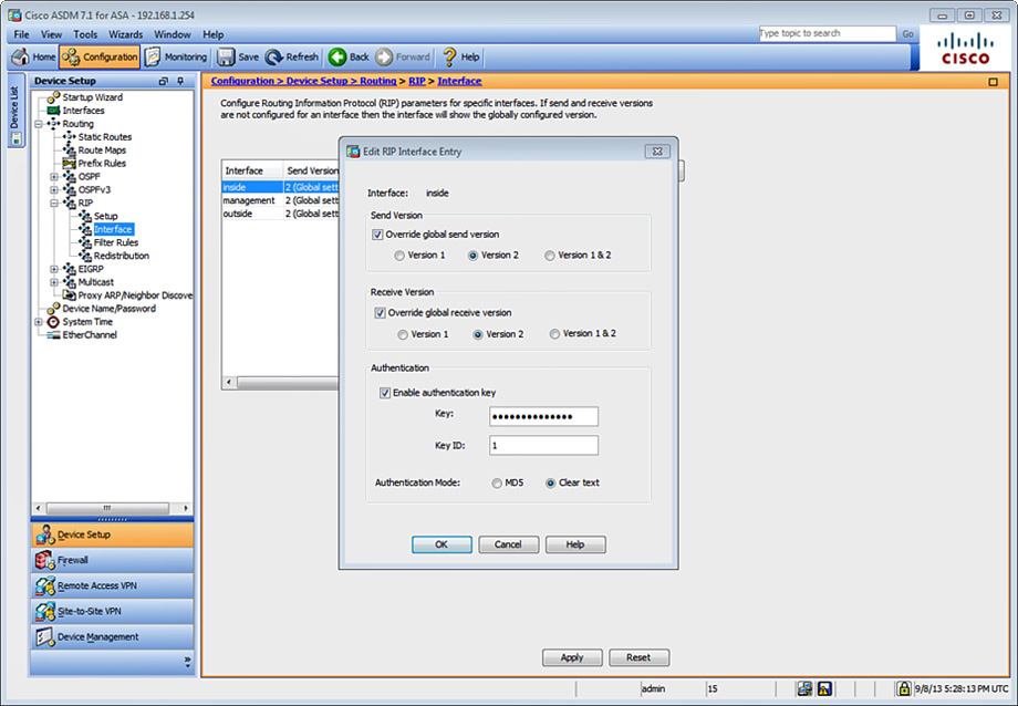
3. (Optional) Check the Override Global Send Version check box to choose the RIP version sent by the interface. Click Version 2 for this example, as indicated in the diagram in Figure 12-10. You can disable this option to restore the global setting.
4. Check the Enable Authentication Key check box to enable RIP authentication.
5. In the Key field, enter the key to be used for RIP authentication. In Figure 12-11, the key supersecretkey is used (masked). This key can contain up to 16 characters.
6. In the Key ID field, enter the key ID used by the RIP authentication process. The key ID value of 1 is used in this example. The valid values are from 0 to 255.
7. For the Authentication Mode option, click the MD5 radio button.
8. Click OK.
9. Click Apply to apply the configuration changes in ASDM.
10. Click Save to save the configuration on the Cisco ASA.
Example 12-5 shows the commands sent by ASDM to the Cisco ASA.
Example 12-5 RIP Authentication Commands Sent to the Cisco ASA
interface GigabitEthernet0/1
nameif inside
!- RIP is enabled on the inside interface
!- RIP send and receive version is configured for version 2
rip send version 2
rip receive version 2
!- RIP authentication mode is set to MD5
rip authentication mode md5
!- RIP authentication key in the CLI is shown as <removed> by the Cisco ASA for security purposes.
rip authentication key <removed> key_id 1
RIP Route Filtering
The Cisco ASA can be configured to prevent other routers on the local network from learning specific RIP routes. Similarly, it can be configured to filter routes from other routing devices in the network. Figure 12-12 illustrates the topology used for the next example. The goal is to configure the Cisco ASA to filter the route for the 10.10.4.0/24 network from the RIP neighbor router (R1).
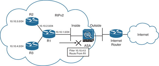
To configure the Cisco ASA to filter the route for the 10.10.4.0/24 network from R1, complete the following steps:
1. Log in to ASDM and navigate to Configuration > Device Setup > Routing > RIP > Filter Rules.
2. Click Add to create a new filter rule. The Add Filter Rules dialog box shown in Figure 12-13 is displayed.
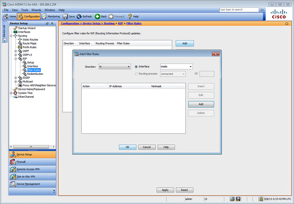
3. Choose in from the Direction drop-down list to filter incoming RIP updates from another routing device (in this case R1). If you wanted to prevent other routing devices from learning one or more RIP routes, you would suppress routes from being advertised in routing updates by choosing out from the Direction drop-down list. However, in this case, the goal is to filter incoming routes from R1.
4. Choose the interface where the routes will be filtered. R1 resides in the inside interface.
5. Click Add to add the filter rule. The Network Rule dialog box shown in Figure 12-14 is displayed.
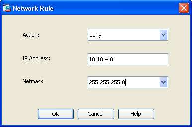
6. Choose Deny in the Action field to deny a specific network or IP address.
7. The goal is to filter the incoming route advertisement for the 10.10.4.0/24 network. Enter 10.10.4.0 in the IP Address field, as shown in Figure 12-14.
8. The 10.10.4.0 network is a 24-bit network. Enter 255.255.255.0 in the Netmask field.
9. Click OK in the Network Rule dialog box to add the new rule.
10. Click OK in the Add Filter Rules dialog box to add the new filter.
11. Click Apply to apply the configuration changes in ASDM and add them to the Cisco ASA’s running configuration.
12. Click Save to save the configuration in the Cisco ASA.
Example 12-6 shows the CLI commands configured in the Cisco ASA by ASDM when creating these RIP filtering rules.
Example 12-6 CLI Commands for Filtering Incoming RIP Routes
!- An access control list (ACL) is created to deny the 10.10.4.0
access-list ripACL_FR standard deny 10.10.4.0 255.255.255.0
!
router rip
distribute-list ripACL_FR in interface inside
! The distribute-list subcommand is used to create the filtering rule.
! The ripACL_FR ACL is applied to the distribute-list command and configured inbound to the inside interface.
Example 12-7 shows the Cisco ASA routing table, using the show route command, after the filter configured in Example 12-6 has been applied.
Example 12-7 Routing Table After Application of Route Filtering Rules
NewYork# show route
Codes: C - connected, S - static, I - IGRP, R - RIP, M - mobile, B - BGP
D - EIGRP, EX - EIGRP external, O - OSPF, IA - OSPF inter area
N1 - OSPF NSSA external type 1, N2 - OSPF NSSA external type 2
E1 - OSPF external type 1, E2 - OSPF external type 2, E - EGP
i - IS-IS, L1 - IS-IS level-1, L2 - IS-IS level-2, ia - IS-IS inter area
* - candidate default, U - per-user static route, o - ODR
P - periodic downloaded static route
Gateway of last resort is 209.165.201.2 to network 0.0.0.0
C 172.18.104.128 255.255.255.192 is directly connected, management
C 209.165.201.0 255.255.255.224 is directly connected, outside
C 10.10.1.0 255.255.255.0 is directly connected, inside
R 10.10.2.0 255.255.255.0 [120/1] via 10.10.1.2, 0:01:24, inside
R 10.10.3.0 255.255.255.0 [120/1] via 10.10.1.2, 0:01:24, inside
S* 0.0.0.0 0.0.0.0 [255/0] via 209.165.201.2, outside
As you see in Example 12-7, the route to the 10.10.4.0/24 network is no longer shown.
Configuring RIP Redistribution
The Cisco ASA can be configured to redistribute routes from other routing processes into RIP. Complete the following steps to configure RIP redistribution using ASDM:
1. Log in to ASDM and navigate to Configuration > Device Setup > Routing > RIP > Redistribution.
2. Click Add to open the Add Redistribution dialog box. Choose the routing protocol being redistributed into the RIP routing process under the Protocol area. You can choose from the following protocols:
![]() Static: Used to redistribute static routes
Static: Used to redistribute static routes
![]() Connected: Used to redistribute directly connected networks
Connected: Used to redistribute directly connected networks
![]() OSPF: Used to redistribute routes learned by a specific OSPF routing process
OSPF: Used to redistribute routes learned by a specific OSPF routing process
![]() EIGRP: Used to redistribute routes learned by a specific EIGRP routing process
EIGRP: Used to redistribute routes learned by a specific EIGRP routing process
3. Enter the metric type and value in the Metric area. This is the RIP metric being applied to the redistributed routes. The metric in this case is set to the number 10.
4. In the Optional area, you can configure route maps to specify with more granularity which routes from the specified routing process are redistributed into RIP.
5. Click OK in the Add Redistribution dialog box.
6. Click Apply to apply the configuration changes in ASDM and add them to the Cisco ASA’s running-configuration.
7. Click Save to save the configuration in the Cisco ASA. Alternatively, you can configure RIP redistribution with the redistribute RIP subcommand. The following example shows the options for the redistribute command:
NewYork(config)# router rip
NewYork(config-router)# redistribute ?
router mode commands/options:
connected Connected
eigrp Enhanced Interior Gateway Routing Protocol (EIGRP)
ospf Open Shortest Path First (OSPF)
rip Routing Information Protocol (RIP)
static Static routes
Troubleshooting RIP
This section includes several commands and techniques that you can use while troubleshooting different issues that may arise throughout your deployment of RIP. A number of scenarios are provided to exemplify these troubleshooting techniques.
Scenario 1: RIP Version Mismatch
Using the same network topology illustrated in Figure 12-12, the internal router was intentionally configured with the incorrect RIP version. The Cisco ASA was configured with RIP version 2 on the inside interface (as previously shown) and the internal router was configured with RIP version 1. The output of the show route command does not display any routes learned via RIP. Example 12-8 shows the output of this command.
Example 12-8 Output of show route Missing RIP Routes
NewYork# show route
Codes: C - connected, S - static, I - IGRP, R - RIP, M - mobile, B - BGP
D - EIGRP, EX - EIGRP external, O - OSPF, IA - OSPF inter area
N1 - OSPF NSSA external type 1, N2 - OSPF NSSA external type 2
E1 - OSPF external type 1, E2 - OSPF external type 2, E - EGP
i - IS-IS, L1 - IS-IS level-1, L2 - IS-IS level-2, ia - IS-IS inter area
* - candidate default, U - per-user static route, o - ODR
P - periodic downloaded static route
Gateway of last resort is 209.165.201.2 to network 0.0.0.0
C 172.18.104.128 255.255.255.192 is directly connected, management
C 209.165.201.0 255.255.255.224 is directly connected, outside
C 10.10.1.0 255.255.255.0 is directly connected, inside
S* 0.0.0.0 0.0.0.0 [255/0] via 209.165.201.2, outside
The debug command debug rip events is used as a troubleshooting tool for this problem, as demonstrated in Example 12-9.
Example 12-9 Output of debug rip events Showing Incorrect RIP Version During Negotiation
NewYork# debug rip events
RIP event debugging is on
NewYork#
RIP: ignored v1 packet from 10.10.1.2 (illegal version)
In the highlighted line, the Cisco ASA displays an error message indicating that the router (10.10.1.2) is sending the incorrect RIP version (v1). The solution to this problem is to configure RIP version 2 on the internal router. Example 12-10 shows the output of debug rip events when the correct information is received from the inside router.
Example 12-10 Output of debug rip events Showing Correct RIP Version During Negotiation
RIP: received v2 update from 10.10.1.2 on inside
10.10.2.0 255.255.255.0 via 0.0.0.0 in 1 hops
10.10.3.0 255.255.255.0 via 0.0.0.0 in 1 hops
10.10.4.0 255.255.255.0 via 0.0.0.0 in 1 hops
RIP: Update contains 3 routes
Notice that the Cisco ASA receives a RIP version 2 (v2) update from the router (10.10.1.2) on the inside interface. Additionally, the routes learned are also displayed.
Scenario 2: RIP Authentication Mismatch
The topology shown in Figure 12-12 is also used in Example 12-11. The internal router and the Cisco ASA were configured to perform RIP authentication using MD5. The MD5 password was configured incorrectly in the inside router (R1). Example 12-11 shows the output of debug rip events on the Cisco ASA, which indicates that there is a problem with MD5 authentication.
Example 12-11 Output of debug rip events Showing Invalid Authentication During Negotiation
RIP: ignored v2 packet from 10.10.1.2 (invalid authentication)
This message also appears if the incorrect authentication method or mode is selected.
Scenario 3: Multicast or Broadcast Packets Blocked
RIPv1 uses broadcast packets and RIPv2 uses multicast packets. If broadcast or multicast packets (respectively) are blocked, the Cisco ASA will successfully establish a RIP neighbor relationship with its peers. The debug rip events command is also useful to troubleshoot this problem. Example 12-12 shows the output of debug rip events while RIPv2 multicast packets are being blocked.
Example 12-12 Output of debug rip events While Multicast Packets Are Being Dropped or Blocked
RIP: sending v2 update to 224.0.0.9 via inside (10.10.1.1)
RIP: build update entries
0.0.0.0 0.0.0.0 via 0.0.0.0, metric 1, tag 0
RIP: Update contains 1 routes
RIP: Update queued
RIP: Update sent via inside rip-len:32
As you can see from Example 12-12, the Cisco ASA is sending the RIPv2 packets to the address 224.0.0.9 without receiving anything back from its peers. You will also see this behavior when RIP is not enabled on any other routing device on that segment.
Tip
You can also ping the multicast address of 224.0.0.9 to verify that packets are not blocked. The Cisco ASA does not respond to pings destined to the 224.0.0.9 address, as opposed to Cisco IOS routers.
OSPF
The OSPF routing protocol was drafted by the IGP Working Group of the Internet Engineering Task Force (IETF). It was developed because RIP was not able to scale for large, heterogeneous networks. The OSPF specification is defined in RFC 2328, “OSPF Version 2.” It is based on the Shortest Path First (SPF) algorithm (usually referred to as the Dijkstra algorithm after its author).
OSPF is a link-state routing protocol. It sends information about attached interfaces, metrics used, and other variables to its peers or neighbors. This information is called a link-state advertisement (LSA). LSAs are sent to all the peers within a specific hierarchical area.
OSPF operates in hierarchies of separate autonomous systems. These autonomous systems can be divided into groups of contiguous networks called areas. A router that is part of more than one area is referred to as an Area Border Router (ABR). Figure 12-15 illustrates an example of this concept.
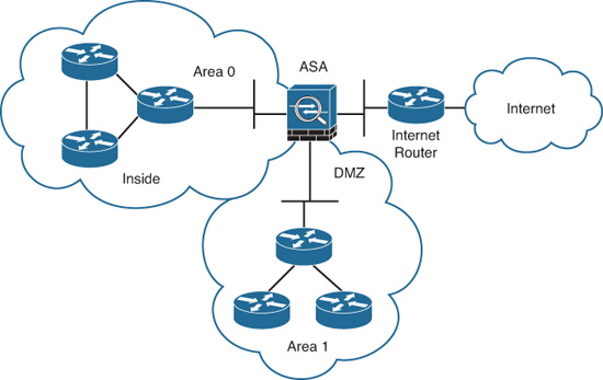
As shown in Figure 12-15, more than one OSPF area can be joined together by an ABR. On the other hand, an OSPF backbone, OSPF area 0, must be present to propagate routing information to all other areas. The Cisco ASA can be configured to act as an ABR. It then can provide not only connectivity, but also security while performing Type 3 LSA filtering. Type 3 LSAs refer to summary links and are sent by ABRs to advertise destinations outside an area. The OSPF ABR Type 3 LSA filtering feature gives the user improved control of route distribution between OSPF areas. This feature also provides the capability of hiding the private networks by using Network Address Translation (NAT) without advertising them.
Figure 12-16 provides an example of how the Cisco ASA is configured as an ABR and how it provides LSA type 3 filtering.
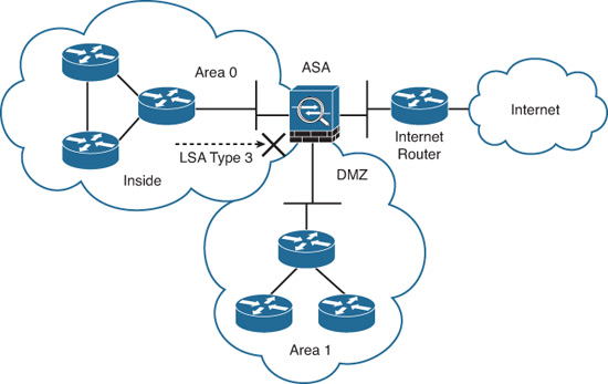
If the Cisco ASA is configured as an Autonomous System Boundary Router (ASBR), it propagates Type 5 LSAs for the entire autonomous system, including areas in private and public networks. Type 5 LSAs provide external routes to the autonomous system. This is not a recommended security practice because this causes all private networks to be externally advertised.
The ospf database-filter all out command is used to filter out all outgoing LSAs to an OSPF interface during synchronization and flooding.
The following section provides different sample configurations explaining all the OSPF features supported by Cisco ASA.
Configuring OSPF
Cisco ASA supports several OSPF features and capabilities. The following summarizes the Cisco ASA OSPF support:
![]() Intra-area, inter-area, and external (Type 1 and Type 2) routes
Intra-area, inter-area, and external (Type 1 and Type 2) routes
![]() Support to act as a designated router (DR)
Support to act as a designated router (DR)
![]() Support to act as a backup designated router (BDR)
Support to act as a backup designated router (BDR)
![]() Support to act as an ABR
Support to act as an ABR
![]() Support to act as an ASBR, with route redistribution between OSPF processes including OSPF, static, and connected routes
Support to act as an ASBR, with route redistribution between OSPF processes including OSPF, static, and connected routes
![]() Virtual links
Virtual links
![]() OSPF authentication (both cleartext and MD5 authentication)
OSPF authentication (both cleartext and MD5 authentication)
![]() Stub areas and not-so-stubby areas (NSSA)
Stub areas and not-so-stubby areas (NSSA)
![]() LSA flooding
LSA flooding
![]() ABR type 3 LSA filtering
ABR type 3 LSA filtering
![]() OSPF neighbor command and dynamic routing over a virtual private network (VPN) tunnel
OSPF neighbor command and dynamic routing over a virtual private network (VPN) tunnel
![]() Load balancing between a maximum of three peers on a single interface, using equal-cost multipath (ECMP) routes
Load balancing between a maximum of three peers on a single interface, using equal-cost multipath (ECMP) routes
The following sections provide configuration examples for most of these features.
Enabling OSPF
The topology illustrated in Figure 12-17 is used in this example. It includes a Cisco ASA connected to a router named R1 on its inside interface. This router is also connected to two other routers (R2 and R3).
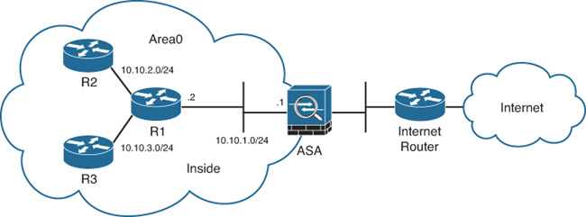
In Figure 12-17, the Cisco ASA, R1, R2, and R3 are all configured in area 0.
To initially design OSPF, perform these tasks:
1. Log in to ASDM and navigate to Configuration > Device Setup > Routing > OSPF > Setup.
2. The Cisco ASA supports up to only two OSPF process instances on its configuration. Each OSPF process has its own associated areas and networks. To enable an OSPF process, check Enable This OSPF Process for one of the two available processes, as shown in Figure 12-18. In this example, use OSPF Process 1.

3. In the OSPF Process ID field, enter a unique numeric identifier for the respective OSPF process. In this example, enter a process ID of 1. The Cisco ASA uses this process ID internally and does not need to match the OSPF process ID on any other routing device. You can enter any value from 1 to 65535.
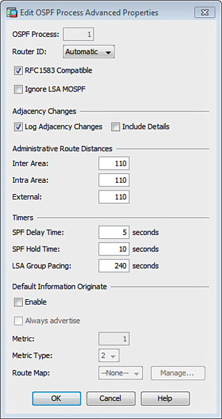
4. (Optional) You can click the Advanced button to open the Edit OSPF Process Advanced Properties dialog box, shown in Figure 12-19, and configure additional OSPF parameters such as Router ID, Adjacency Changes, Administrative Route Distances, Timers, and Default Information Originate settings. Figure 12-19 shows the default options. In this example, accept the default values for simplicity and click OK to close the dialog box.
5. Configure the area properties and area network for the OSPF process by navigating to the Area/Networks tab.
6. Click Add to open the Add OSPF Area dialog box, shown in Figure 12-20, and add the specific networks.
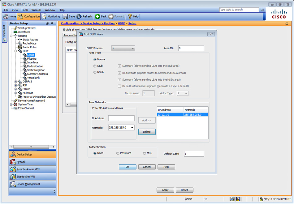
7. In the OSPF Process field, identify the OSPF process you want to edit, which in this example is OSPF process 1.
8. Enter the area ID in the Area ID field. In this case, Area 0 is used; however, area values range from 0 to 4294967295. Enter the area ID using an IP address.
9. There are three different area types from which to choose:
![]() Normal: Makes the area a standard OSPF area. This is the default option when an area is initially created, and is the one used in this example.
Normal: Makes the area a standard OSPF area. This is the default option when an area is initially created, and is the one used in this example.
![]() Stub: Makes the area a stub area. Stub areas stop AS External LSAs (type 5 LSAs) from being flooded into the stub area. When you create a stub area, the Summary check box is available. You can prevent summary LSAs (type 3 and 4) from being flooded into the area by not checking the Summary check box.
Stub: Makes the area a stub area. Stub areas stop AS External LSAs (type 5 LSAs) from being flooded into the stub area. When you create a stub area, the Summary check box is available. You can prevent summary LSAs (type 3 and 4) from being flooded into the area by not checking the Summary check box.
![]() NSSA: Makes the area a not-so-stubby area. NSSAs accept type 7 LSAs. As with stub area configuration, uncheck the Summary check box to stop summary LSAs from being flooded into the area. You can also disable route redistribution by unchecking the Redistribute check box and checking the Default Information Originate check box.
NSSA: Makes the area a not-so-stubby area. NSSAs accept type 7 LSAs. As with stub area configuration, uncheck the Summary check box to stop summary LSAs from being flooded into the area. You can also disable route redistribution by unchecking the Redistribute check box and checking the Default Information Originate check box.
Checking the Default Information Originate check box enables the Cisco ASA to generate a type 7 default into the NSSA. This option is disabled by default. You can also specify the OSPF metric value for the default route (in the range from 0 to 16777214) in the Metric Value field. The default value is 1. Use the Metric Type field to specify the OSPF metric type for the default route. You can choose 1 for type 1 or 2 for type 2. If Default Information Originate is checked, the default value is 2.
10. Define the networks in the area by entering the IP address and netmask of the networks in the respective fields under Area Networks. For this example, add the 10.10.1.0/24 network with a netmask of 255.255.255.0, as shown in Figure 12-20.
Note
The Add OSPF Area dialog box also enables you to configure OSPF authentication, which is covered later in this chapter.
Example 12-13 shows the CLI commands generated by ASDM and sent to the Cisco ASA.
Example 12-13 Basic CLI OSPF Configuration
router ospf 1
network 10.10.1.0 255.255.255.0 area 0
log-adj-changes
The router ospf command enables OSPF and defines the OSPF process. The number 1 is used as an identification parameter for the OSPF routing process. The network command specifies the interfaces that run OSPF. Furthermore, it specifies the area to be associated with that interface. Use the network address or the address of the interface where you want to enable OSPF.
Example 12-14 shows the output of the show route inside command after OSPF was configured in the Cisco ASA.
Example 12-14 Output of show route inside After Basic OSPF Configuration
NewYork# show route inside
Codes: C - connected, S - static, I - IGRP, R - RIP, M - mobile, B - BGP
D - EIGRP, EX - EIGRP external, O - OSPF, IA - OSPF inter area
N1 - OSPF NSSA external type 1, N2 - OSPF NSSA external type 2
E1 - OSPF external type 1, E2 - OSPF external type 2, E - EGP
i - IS-IS, L1 - IS-IS level-1, L2 - IS-IS level-2, ia - IS-IS inter area
* - candidate default, U - per-user static route, o - ODR
P - periodic downloaded static route
Gateway of last resort is 209.165.201.2 to network 0.0.0.0
C 10.10.1.0 255.255.255.0 is directly connected, inside
O 10.10.3.0 255.255.255.0 [110/11] via 10.10.1.2, 0:28:15, inside
O 10.10.2.0 255.255.255.0 [110/11] via 10.10.1.2, 0:28:15, inside
The output of show route inside has two routes learned via OSPF on the inside interface of Cisco ASA. The first number in the brackets is the administrative distance of the information source. The second number is the metric for the route.
The show ospf command is used to display the general information about the OSPF routing processes. Example 12-15 shows the output of the show ospf command in the Cisco ASA.
Example 12-15 Output of show ospf After Basic OSPF Configuration
NewYork# show ospf
Routing Process "ospf 1" with ID 209.165.201.1 and Domain ID 0.0.0.1
Supports only single TOS(TOS0) routes
Does not support opaque LSA
SPF schedule delay 5 secs, Hold time between two SPFs 10 secs
Minimum LSA interval 5 secs. Minimum LSA arrival 1 secs
Number of external LSA 0. Checksum Sum 0x 0
Number of opaque AS LSA 0. Checksum Sum 0x 0
Number of DCbitless external and opaque AS LSA 0
Number of DoNotAge external and opaque AS LSA 0
Number of areas in this router is 1. 1 normal 0 stub 0 nssa
External flood list length 0
Area BACKBONE(0)
Number of interfaces in this area is 1
Area has no authentication
SPF algorithm executed 2 times
Area ranges are
Number of LSA 3. Checksum Sum 0x 15b1f
Number of opaque link LSA 0. Checksum Sum 0x 0
Number of DCbitless LSA 0
Number of indication LSA 0
Number of DoNotAge LSA 0
Flood list length 0
The highlighted lines in Example 12-15 show the OSPF process information and that area 0 is associated to this process and active in only one interface (the inside interface in this case).
OSPF Virtual Links
All areas must talk to area 0 (the backbone area). It’s likely that this will not always be possible. However, in OSPF, virtual links can be configured to connect an area through a non-backbone area. They can also be used to connect two parts of a segmented backbone through non-backbone areas.
Figure 12-21 illustrates the topology of the network used in the following example. The Cisco ASA is configured with a virtual link to a router located on a DMZ interface.
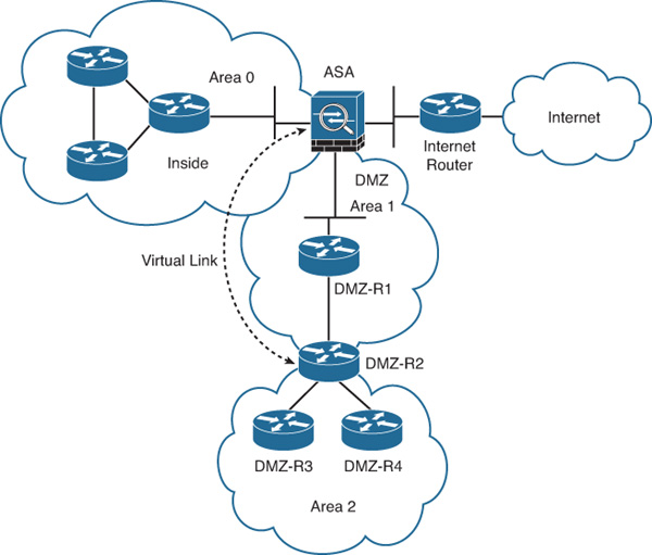
To configure the virtual link on the Cisco ASA for the network shown in Figure 12-21, complete the following steps:
1. Log in to ASDM and navigate to Configuration > Device Setup > Routing > OSPF > Virtual Link.
2. Click Add to add a new virtual link. The dialog box shown in Figure 12-22 is displayed.

4. Choose the OSPF process associated with the virtual link. In this case, choose OSPF process 1.
5. From the Area ID drop-down list, choose the area shared by the neighbor OSPF devices, which is 1 in this example. Please note that NSSA or stub areas cannot be associated with a virtual link.
6. Enter the router ID of the virtual link neighbor in the Peer Router ID field. The virtual link peer in this example is DMZ-R2, which has the router ID 10.10.5.1.
Note
You can click the Advanced button to configure more OSPF properties for the virtual link in this area. These properties include authentication and packet interval settings. This example uses all default values for these properties.
At first, the virtual link is down because the Cisco ASA does not know how to reach the router labeled DMZ-R2. All the LSAs in area 1 need to be flooded, and the shortest path first (SPF) algorithm must run within area 1 for the Cisco ASA to successfully reach DMZ-R2 through area 1. In this case, area 1 is the transit area. After the Cisco ASA reaches DMZ-R2, the router and the Cisco ASA try to form an adjacency across the virtual link. After the Cisco ASA and the DMZ-R2 router become adjacent on the virtual link, DMZ-R2 becomes an ABR because it now has a link in area 0. Consequently, a summary LSA for the networks in area 0 and area 1 is created.
Example 12-16 shows the CLI commands sent by ASDM to the Cisco ASA to create the virtual link to the DMZ-R2 router.
Example 12-16 OSPF Virtual Link CLI Configuration
router ospf 1
network 10.10.1.0 255.255.255.0 area 0
network 10.10.4.0 255.255.255.0 area 1
area 1 virtual-link 10.10.5.1
The highlighted line in Example 12-16 shows that the area 1 virtual-link command is used to create the virtual link to 10.10.5.1.
The show ospf virtual-links command can be used to display statistical information about an OSPF virtual link. The output of show ospf virtual-links is included in Example 12-17.
Example 12-17 Output of show ospf virtual-links Command
New York# show ospf virtual-links
Virtual Link dmz to router 10.10.5.1 is up
Run as demand circuit
DoNotAge LSA allowed.
Transit area 1, via interface dmz, Cost of using 10
Transmit Delay is 1 sec, State UP,
Timer intervals configured, Hello 10, Dead 40, Wait 40, Retransmit
The highlighted line in Example 12-17 show that the virtual link to the DMZ-R2 router (10.10.5.1) is up.
Configuring OSPF Authentication
Cisco ASA supports both plain-text and MD5 OSPF authentication. MD5 authentication is recommended because it is more secure than plain-text authentication. When configuring authentication, an entire area must be configured with the same type of authentication. For example, if area 1 is configured for MD5 authentication, all devices running OSPF must run MD5 authentication. Figure 12-23 includes an example of a Cisco ASA performing MD5 authentication on its inside interface. All routers and the Cisco ASA reside in area 0, and they must use the same authentication type and shared secret (password) to learn routes from each other.

Complete the following steps to configure OSPF MD5 authentication using ASDM:
1. Log in to ASDM and navigate to Configuration > Device Setup > Routing > OSPF > Setup.
2. Click the Area / Networks tab and select the OSPF Process where MD5 authentication is to be enabled. In this example, select OSPF process 1.
3. Click Edit to edit the OSPF process settings. The dialog box shown in Figure 12-24 is displayed.
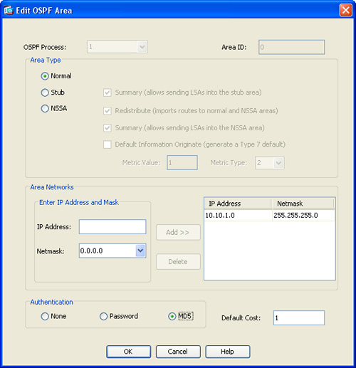
4. Click MD5 in the Authentication area.
6. Click Apply to apply the OSPF process changes.
7. Navigate to Configuration > Device Setup > Routing > OSPF > Interface.
8. Select the interface where OSPF MD5 authentication is to be enabled and click Edit. In this example, OSPF MD5 authentication is enabled in the inside interface.
9. The dialog box shown in Figure 12-25 is displayed. Click MD5 Authentication in the Authentication area.
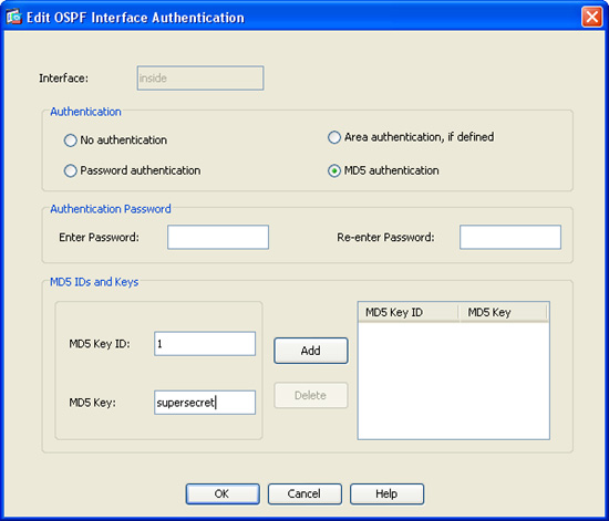
10. Enter the MD5 Key ID in the MD5 IDs and Keys area. The MD5 Key ID is a numerical identifier. This identifier can be any number from 1 to 255. The number 1 is used in this case.
11. Enter the MD5 Key. This is the shared secret used by the Cisco ASA and the OSPF peer. This is an alphanumeric character string of up to 16 bytes. The key supersecret is used in this example.
12. Click Add to add the MD5 Key ID and MD5 Key settings.
13. Click OK.
14. Click Apply to apply the configuration changes.
15. Click Save to save the configuration in the Cisco ASA.
Example 12-18 shows the CLI commands sent by ASDM to the Cisco ASA to enable OSPF MD5 authentication.
Example 12-18 OSPF MD5 Authentication CLI Commands
router ospf 1
area 0 authentication message-digest
! MD5 authentication is enabled for area 0
!
interface GigabitEthernet0/1
nameif inside
! OSPF MD5 authentication is enabled under the inside interface
! The MD5 Key ID is 1 and the shared secret is supersecret.
ospf message-digest-key 1 md5 supersecret
ospf authentication message-digest
Tip
Although plain-text authentication is less secure than MD5 authentication, it is sometimes used when communicating with Layer 3 devices that do not support MD5 authentication.
OSPF virtual links can also be authenticated with MD5 or plain-text authentication. The following steps show how to enable MD5 authentication in the virtual link configuration previously discussed in the “OSPF Virtual Links” section and Figure 12-21:
1. Log in to ASDM and navigate to Configuration > Device Setup > Routing > OSPF > Virtual Link.
2. Select the virtual link that was previously configured and click Edit to open the Edit OSPF Virtual Link dialog box.
3. Click Advanced to configure the advanced OSPF virtual link properties. The dialog box shown in Figure 12-26 is displayed.
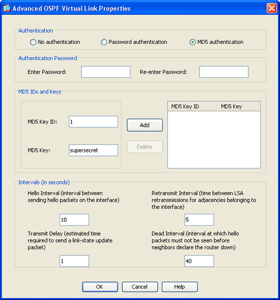
4. Click MD5 Authentication in the Authentication area.
5. Enter the MD5 Key ID and MD5 Key in the MD5 IDs and Keys area. In this example, the MD5 Key ID is the number 1 and the MD5 Key is supersecret.
6. Click Add to add the MD5 Key ID and the MD5 Key to the table on the right.
7. Click OK to close the Advanced OSPF Virtual Link Properties dialog box.
8. Click OK to close the Edit OSPF Virtual Link dialog box.
9. Click Apply to apply the configuration changes in ASDM and add them to the Cisco ASA’s running configuration.
10. Click Save to save the configuration in the Cisco ASA.
Example 12-19 shows the CLI commands sent by ASDM to the Cisco ASA to enable OSPF virtual link MD5 authentication.
Example 12-19 OSPF Virtual Link MD5 Authentication CLI Commands
router ospf 1
area 0 virtual-link 10.10.5.1 authentication message-digest
area 0 virtual-link 10.10.5.1 message-digest-key 1 md5 supersecret
The second line in Example 12-19 shows that MD5 (message-digest) authentication is enabled in the virtual link to 10.10.5.1. The third line shows that the MD5 key ID 1 is added with the message-digest-key keyword, as well as the MD5 key (supersecret) with the md5 keyword.
Configuring OSPF Redistribution
The Cisco ASA can be configured to act as an ASBR. It can perform route redistribution between different OSPF processes, other dynamic routing protocols, static routes, or directly connected subnets. Complete the following steps to configure OSPF redistribution using ASDM.
1. Log in to ASDM and navigate to Configuration > Device Setup > Routing > OSPF > Redistribution.
2. Click Add to add an OSPF redistribution entry. The dialog box shown in Figure 12-27 is displayed.
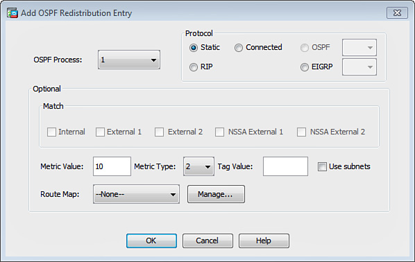
3. In the OSPF Process drop-down list, choose the OSPF process where redistribution will be configured. OSPF process 1 is used in this example.
4. In the Protocol area, choose the protocol to be redistributed under the Protocol area. This example shows how to redistribute all the static routes into OSPF.
5. In the Optional area, enter in the Metric Value field the metric that is used for the redistribute routes (10 in this example). This field is blank for redistribution entries if the default metric is used.
6. In the Metric Type drop-down menu, choose the metric type: 1 specifies that the route is a Type 1 external route; 2 specifies that the metric is a Type 2 external route. Type 2 routes are specified in this example.
7. (Optional) You can configure a 32-bit decimal tag in the Tag Value field. This is an identifier used on each external route. This value is not used by the Cisco ASA itself; however, it may be used by other routing devices to communicate information between ASBRs. You can configure this tag with any value from 0 to 4294967295.
8. (Optional) You can configure route maps to specify with more granularity which routes from the specified routing process are redistributed into RIP.
9. Check the Use Subnets check box to enable the redistribution of subnetted routes. Uncheck this box to cause only routes that are not subnetted to be redistributed.
10. Click OK to close the Add OSPF Redistribution Entry dialog box.
11. Click Apply to apply the configuration changes.
12. Click Save to save the configuration in the Cisco ASA.
Example 12-20 shows the CLI commands sent by ASDM to the Cisco ASA to enable OSPF virtual link MD5 authentication.
Example 12-20 OSPF Virtual Link MD5 Authentication CLI Commands
router ospf 1
redistribute static metric 10 subnets
The first line indicates that static routes are redistributed into OSPF. The redistribute static command is used to enable OSPF redistribution for static routes. In Example 12-20, the static routes are redistributed with a metric value of 10.
Tip
Use the subnets attribute to allow the Cisco ASA to consider any configured subnets. This is commonly used when other routing protocols are being redistributed into OSPF. Only classful routes are redistributed if you do not specify the subnets attribute.
Stub Areas and NSSAs
An ASBR advertises external routes throughout the OSPF autonomous system. However, in some situations, there is no need to advertise external routes into an area, in which case you can reduce the size of the OSPF database by blocking advertisements to that area. A stub area is an area that does not allow the advertisements of external routes. In stub areas, a default summary route is injected along with information about networks that belong to other areas within the same OSPF network.
To use ASDM to configure an area as a stub area, complete the following steps:
1. Log in to ASDM and navigate to Configuration > Device Setup > Routing > OSPF > Setup.
2. Click the Area / Networks tab.
3. Click Add to add an area, or click Edit to edit an area.
4. In the Area Type area, click the Stub radio button.
5. Click OK.
6. Click Apply to apply the configuration changes.
7. Click Save to save the configuration in the Cisco ASA.
Alternatively, you can use the CLI stub option with the area OSPF subcommand to configure this feature in the Cisco ASA. The following is the command syntax:
area area-id stub [no-summary]
Tip
Use the no-summary attribute if you do not want to send summary LSAs into the stub area.
If an area is configured as a stub, all the routers within the area must also be configured as stub routers. Otherwise, the neighbor relationship is not established.
The OSPF NSSA feature is defined in RFC 3101, “The OSPF Not-So-Stubby Area (NSSA) Option.” Redistribution of routes into an NSSA generates a special type of LSA known as LSA type 7. This type only exists in NSSAs.
To use ASDM to configure an area as an NSSA, complete the following steps:
1. Log in to ASDM and navigate to Configuration > Device Setup > Routing > OSPF > Setup.
2. Click the Area / Networks tab.
3. Click Add to add an area, or click Edit to edit an area.
4. In the Area Type area, click NSSA.
6. Click Apply to apply the configuration changes.
7. Click Save to save the configuration in the Cisco ASA.
In the CLI, you can use the nssa option with the area OSPF subcommand to configure this feature in the Cisco ASA. The following is the command syntax:
area area-id nssa [no-redistribution][default-information-originate [metric
metric] [metric-type 1|2]][no-summary]
OSPF Type 3 LSA Filtering
The Cisco ASA supports OSPF Type 3 LSA filtering. Follow these steps to use ASDM to configure OSPF Type 3 LSA filtering:
1. Log in to ASDM and navigate to Configuration > Device Setup > Routing > OSPF > Filtering.
2. Click Add to add OSPF filtering rules. The dialog box shown in Figure 12-28 is displayed.
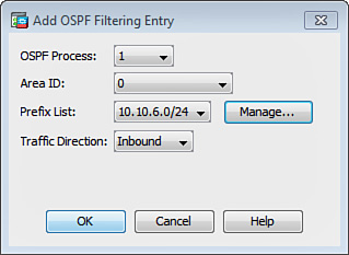
3. In the OSPF Process drop-down list, choose the OSPF process to be associated with the filter entry; in this case, OSPF process 1 is chosen.
4. Choose the Area ID to be associated with the filter entry. Area 0 is chosen in this example.
5. In the Prefix List drop-down list, choose the prefix list to be filtered. If you have not configured a prefix list, click Manage and add the new prefix list. Select the network address and subnet mask bit to be filtered in the Filtered Network field and click OK to close the Manage dialog box. In this example, the network 10.10.6.0/24 is filtered.
6. From the Traffic Direction drop-down menu, choose the direction in which the filter is applied. The Inbound direction is used in Figure 12-28; with this configuration, the Cisco ASA filter entry applies to LSAs coming into area 0.
7. Click OK.
8. Enter the sequence number to be used for the filter entry under the Sequence # field. The sequence number employed in Figure 12-28 is 1. This sequence number is used if multiple filters are configured on the Cisco ASA; the filter with the lowest sequence number is applied first.
The Cisco ASA begins the search at the top of the prefix list. After a match or deny occurs, the Cisco ASA does not need to go through the rest of the prefix list.
Note
For efficiency, you may want to put the most common matches or denials near the top of the list.
9. Choose the Action to be applied to this filter. In this example, the deny action is selected to deny any route advertisements for the 10.10.6.0/24 network.
10. (Optional) You can specify the minimum prefix length to be matched with an OSPF filter in the Lower Range field. In this case, the field is left blank.
11. (Optional) You can specify the maximum prefix length to be matched with an OSPF filter in the Upper Range field. Here the field is left blank.
12. Click OK.
13. Click Apply to apply the configuration changes.
14. Click Save to save the configuration in the Cisco ASA.
To filter Type 3 LSAs in the Cisco ASA via the CLI, use the prefix-list command. After it is configured, the Cisco ASA controls which prefixes are sent from one area to another. The syntax of the prefix-list command is as follows:
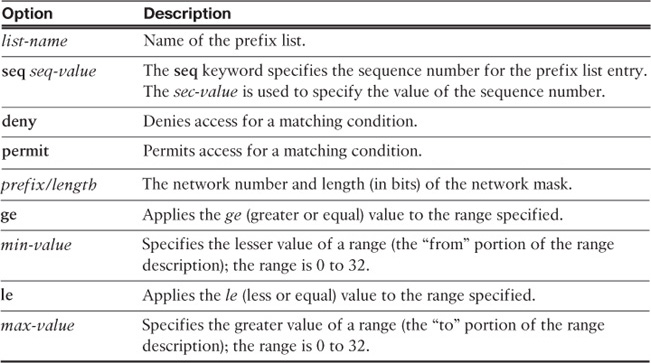
prefix-list list-name [seq seq-value] {deny | permit prefix/length} [ge min-value]
[le max-value]
Table 12-2 lists all the options of the prefix-list command.
You can enter a description (up to 225 characters) for each prefix list by using the prefix-list list-name description command.
OSPF neighbor Command and Dynamic Routing over a VPN Tunnel
OSPF Hello messages are sent over multicast by default. However, IPsec does not support multicast over a VPN tunnel. Consequently, OSPF adjacency using multicast cannot be established over IPsec VPN tunnels. Cisco ASA provides a solution to this problem by supporting the configuration of statically defined neighbors. When you configure a statically defined neighbor, the Cisco ASA communicates with its peers using unicast packets. This enables the OSPF messages to be successfully encrypted and sent over the VPN tunnel.
The OSPF neighbors can be defined only on nonbroadcast media. Because the underlying physical media is Ethernet (broadcast), the media type must be changed to non-broadcast under the interface configuration. This overrides the default physical broadcast media type.
To configure a static OSPF neighbor using ASDM, complete the following steps:
1. Log in to ASDM and navigate to Configuration > Device Setup > Routing > OSPF > Static Neighbor.
2. Click Add to add a new neighbor.
3. Choose the OSPF Process to be used for this entry.
4. Enter the neighbor IP address in the Neighbor field.
5. From the Interface drop-down list, choose the interface where the neighbor resides.
6. Click OK.
7. Click Apply to apply the configuration changes.
8. Click Save to save the configuration in the Cisco ASA.
Alternatively, you can use the neighbor command to specify an OSPF neighbor.
Example 12-21 demonstrates how to use the neighbor command for an IPsec peer located at 209.165.201.2.
Example 12-21 OSPF Static Neighbors
New York(config)# router ospf 1
New York(config-router)# neighbor 209.165.201.2 interface outside
INFO: Neighbor command will take effect only after OSPF is enabled
and network-type is configured on the interface
Notice the warning message in Example 12-21. The command does not take effect until the network type is changed to non-broadcast under the interface. Use the ospf network point-to-point non-broadcast interface command to accomplish this. Example 12-22 demonstrates this command.
Example 12-22 Changing the Default Physical Media Type to Nonbroadcast
New York(config-router)# interface GigabitEthernet0/0
New York(config-if)# ospf network point-to-point non-broadcast
Additionally, OSPF expects neighbors to belong to the same subnet. The subnet requirement is overlooked for point-to-point links. Because the IPsec site-to-site VPN tunnels are considered a point-to-point connection, the previous command provides the solution to this problem. Only one neighbor can be configured on a point-to-point link.
After an interface is declared to be a point-to-point nonbroadcast link, it cannot form adjacencies unless neighbors are configured explicitly.
If OSPF is configured to run over a site-to-site IPsec tunnel, then that same interface cannot form an OSPF neighbor with the directly connected router.
The following are several key points to take into consideration when configuring OSPF over a VPN tunnel:
![]() When configuring OSPF, only one neighbor can be defined for each interface. Additionally, you must configure a static route pointing to the IPsec peer.
When configuring OSPF, only one neighbor can be defined for each interface. Additionally, you must configure a static route pointing to the IPsec peer.
![]() An OSPF adjacency cannot be established unless static neighbors are configured.
An OSPF adjacency cannot be established unless static neighbors are configured.
![]() If OSPF over a VPN connection is running on a given interface, you cannot run any other OSPF instance or neighbor on the same interface.
If OSPF over a VPN connection is running on a given interface, you cannot run any other OSPF instance or neighbor on the same interface.
![]() It is recommended to bind the crypto-map to the interface before configuring the OSPF neighbor. This is done to make sure that the OSPF updates are sent over the VPN tunnel.
It is recommended to bind the crypto-map to the interface before configuring the OSPF neighbor. This is done to make sure that the OSPF updates are sent over the VPN tunnel.
On IPsec site-to-site and remote-access VPN configurations, you can optionally use reverse route injection (RRI). RRI is a feature on the Cisco ASA that provides a solution for topologies that require encrypted traffic to be diverted to the Cisco ASA and all other traffic to be sent to a separate router. In other words, RRI eliminates the need to manually define static routes on internal routers or hosts to be able to send traffic to remote site-to-site connections or remote-access VPN connections. RRI is not required if the Cisco ASA is used as the default gateway and all traffic passes through it to get into and out of the network.
Note
RRI is covered in detail in Chapter 19, “Site-to-Site IPsec VPNs,” and Chapter 20, “IPsec Remote-Access VPNs.”
There are several advantages to running OSPF over an IPsec VPN tunnel instead of using RRI. One of the major advantages is that when RRI is used, the routes to the remote networks or hosts are always advertised to the internal network, regardless of whether or not the VPN tunnel is operational. When using OSPF over an IPsec site-to-site tunnel, the routes to the remote networks or hosts are advertised only if the VPN tunnel is operational.
OSPFv3
The Cisco ASA supports OSPF version 3 for IPv6 support. To enable OSPFv3, perform the following steps:
1. Navigate to Configuration > Device Setup > Routing > OSPFv3 > Setup.
2. On the Process Instances tab, check the Enable OSPFv3 Process check box. You can enable up to two OSPF process instances.
3. Enter a process ID in the Process ID field. The ID can be any positive integer.
4. Click OK.
5. Click Apply to apply the configuration changes.
6. Click Save to save the configuration in the Cisco ASA.
All other OSPF configuration options such as redistribution, static neighbors, virtual links, and summary prefixes are configured the same way as in OSPFv2.
Troubleshooting OSPF
This section includes many mechanisms and techniques that are used to troubleshoot OSPF problems, such as several show and debug commands.
Useful Troubleshooting Commands
A commonly used command is show ospf [process-id]. It displays general information about OSPF routing-process IDs. The process-ID option displays information for a specific OSPF routing process. Example 12-23 shows the output of this command.
Example 12-23 Output of the show ospf [process-id] Command
NewYork# show ospf 1
Routing Process "ospf 1" with ID 192.168.10.1 and Domain ID 0.0.0.1
Supports only single TOS(TOS0) routes
Does not support opaque LSA
SPF schedule delay 5 secs, Hold time between two SPFs 10 secs
Minimum LSA interval 5 secs. Minimum LSA arrival 1 secs
Number of external LSA 0. Checksum Sum 0x 0
Number of opaque AS LSA 0. Checksum Sum 0x 0
Number of DCbitless external and opaque AS LSA 0
Number of DoNotAge external and opaque AS LSA 0
Number of areas in this router is 1. 1 normal 0 stub 0 nssa
External flood list length 0
Area BACKBONE(0)
Number of interfaces in this area is 1
Area has no authentication
SPF algorithm executed 5 times
Area ranges are
Number of LSA 3. Checksum Sum 0x 1da9c
Number of opaque link LSA 0. Checksum Sum 0x 0
Number of DCbitless LSA 0
Number of indication LSA 0
Number of DoNotAge LSA 0
Flood list length 0
As demonstrated in Example 12-23, the show ospf command provides details such as:
![]() OSPF configuration
OSPF configuration
![]() LSA information
LSA information
![]() OSPF router ID
OSPF router ID
![]() Number of areas configured in the Cisco ASA
Number of areas configured in the Cisco ASA
To display OSPF-related interface information, use the show ospf interface command. Example 12-24 includes the output of this command for the inside interface.
Example 12-24 Output of the show ospf interface Command
NewYork# show ospf interface inside
inside is up, line protocol is up
Internet Address 192.168.10.1 mask 255.255.255.0, Area 0
Process ID 1, Router ID 192.168.10.1, Network Type BROADCAST, Cost: 10
Transmit Delay is 1 sec, State BDR, Priority 1
Designated Router (ID) 192.168.10.2, Interface address 192.168.10.2
Backup Designated router (ID) 192.168.10.1, Interface address 192.168.10.1
Timer intervals configured, Hello 10, Dead 40, Wait 40, Retransmit 5
Hello due in 0:00:00
Index 1/1, flood queue length 0
Next 0x0(0)/0x0(0)
Last flood scan length is 1, maximum is 1
Last flood scan time is 0 msec, maximum is 0 msec
Neighbor Count is 1, Adjacent neighbor count is 1
Adjacent with neighbor 192.168.10.2 (Designated Router)
Suppress hello for 0 neighbor(s)
The output of the show ospf interface command shows not only information about the OSPF communication on that specific interface, but also other information, such as the network type, cost, designated router information, and so on.
To display OSPF neighbor information, use the show ospf neighbor command. The following is the command syntax:
show ospf neighbor [interface-name] [neighbor-id] [detail]
To show neighbor information on a per-interface basis, use the interface-name argument. Use the neighbor-id option to display information about a specific neighbor, and use the detail option to display detailed neighbor information. The interface-name and neighbor-id options are mutually exclusive. Example 12-25 shows the output of the show ospf neighbor command.
Example 12-25 Output of the show ospf neighbor Command
NewYork# show ospf neighbor
Neighbor ID Pri State Dead Time Address Interface
192.168.10.2 1 FULL/DR 0:00:34 192.168.10.2 inside
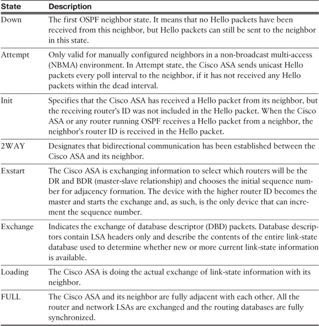
When OSPF adjacency is formed, the Cisco ASA goes through several state changes before it becomes fully adjacent with its neighbor. The information that these states represent is crucial when troubleshooting OSPF problems in the Cisco ASA. These states are as illustrated in Table 12-3.
Example 12-26 shows the output of the show ospf neighbor command with the detail option. The neighbor in this case is a router with IP address 192.168.10.2. Notice that the OSPF state is Full and that there were six state changes. Additionally, the neighbor has been up for 26 minutes and 21 seconds.
Example 12-26 Output of the show ospf neighbor detail Command
NewYork# show ospf neighbor inside 192.168.10.2 detail
Neighbor 192.168.10.2, interface address 192.168.10.2
In the area 0 via interface inside
Neighbor priority is 1, State is FULL, 6 state changes
DR is 192.168.10.2 BDR is 192.168.10.1
Options is 0x2
Dead timer due in 0:00:31
Neighbor is up for 00:26:21
Index 1/1, retransmission queue length 0, number of retransmission 1
First 0x0(0)/0x0(0) Next 0x0(0)/0x0(0)
Last retransmission scan length is 1, maximum is 1
Last retransmission scan time is 0 msec, maximum is 0 msec
Use the show ospf database command to display information related to the Cisco ASA OSPF database. The command displays information about the different OSPF LSAs. It presents detailed information about the neighbor router and the state of the neighbor relationship. Example 12-27 shows the output of the show ospf database command.
Example 12-27 Output of the show ospf database Command
NewYork# show ospf database
OSPF Router with ID (192.168.10.1) (Process ID 1)
Router Link States (Area 0)
Link ID ADV Router Age Seq# Checksum Link count
192.168.10.1 192.168.10.1 1943 0x80000005 0x99dd 1
192.168.10.2 192.168.10.2 20 0x80000003 0xa1d2 1
Net Link States (Area 0)
Link ID ADV Router Age Seq# Checksum
192.168.10.2 192.168.10.2 1944 0x80000001 0xa2e6
Type-5 AS External Link States
Link ID ADV Router Age Seq# Checksum Tag
192.168.20.0 192.168.10.2 19 0x80000001 0xfa25 0
192.168.13.0 192.168.10.2 19 0x80000001 0x8293 0
192.168.10.0 192.168.10.2 19 0x80000001 0xa72c 0
As demonstrated in Example 12-27, several external routes are learned from router 192.168.10.2. The 192.168.10.2 neighbor is advertising two routes for networks 192.168.20.0/24 and 192.168.13.0/24. Example 12-28 shows the output of the show route command for this example. The letter O by the route statement indicates that the route is learned via OSPF, and the E2 indicates that it is an external type 2 route.
Example 12-28 Output of the show route Command
NewYork# show route
S 0.0.0.0 0.0.0.0 [1/0] via 209.165.200.226, outside
C 209.165.200.224 255.255.255.224 is directly connected, outside
C 192.168.10.0 255.255.255.0 is directly connected, inside
O E2 192.168.20.0 255.255.255.0 [110/10] via 192.168.10.2, 0:00:04, inside
O E2 192.168.13.0 255.255.255.0 [110/10] via 192.168.10.2, 0:00:04, inside
Tip
Confirm that the exact subnet mask is configured on the interfaces that are running OSPF between the Cisco ASA and its neighbor. A subnet mismatch creates a discrepancy in the OSPF database that prevents routes from being installed in the routing tables. Furthermore, the maximum transmission unit (MTU) size must also match between peers.
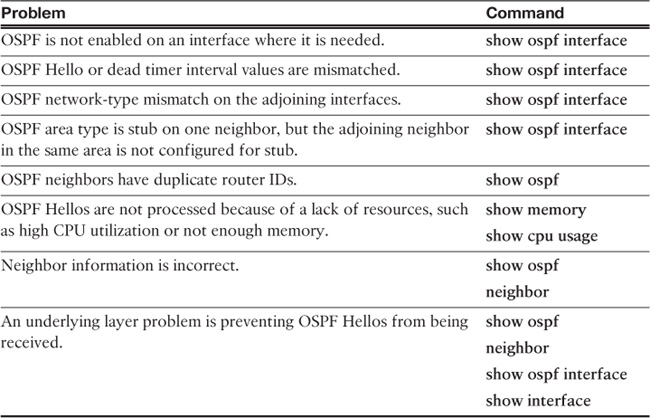
Table 12-4 lists some of the common reasons why OSPF neighbors have problems forming an adjacency and suggests the show commands that you can use to troubleshoot the problem.
The debug ospf command is extremely useful for troubleshooting OSPF problems. However, you should turn on debug commands only if any of the show commands discussed cannot help you solve the problem. Table 12-5 lists all the options of the debug ospf command.

If the debug ospf command is entered without any alternatives, all options are enabled by default. This may not be appropriate for busy OSPF networks.
Example 12-29 shows the output of the debug ospf events command during a new adjacency. The first highlighted line shows that a two-way communication has been started to the router 192.168.10.2 on the inside interface and the state is 2WAY. The second highlighted line shows that non-broadcast (NBR) negotiation has been completed and the Cisco ASA is classified as the slave. The third and fourth highlighted lines indicate that the exchange has been completed and that the state is now FULL.
Example 12-29 Output of the debug ospf events Command
OSPF: Rcv DBD from 192.168.10.2 on inside seq 0x167f opt 0x2 flag 0x7 len 32 mtu
1500 state INIT
OSPF: 2 Way Communication to 192.168.10.2 on inside, state 2WAY
OSPF: Neighbor change Event on interface inside
OSPF: DR/BDR election on inside
OSPF: Elect BDR 192.168.10.2
OSPF: Elect DR 192.168.10.1
DR: 192.168.10.1 (Id) BDR: 192.168.10.2 (Id)
OSPF: Send DBD to 192.168.10.2 on inside seq 0x7c1 opt 0x2 flag 0x7 len 32
OSPF: NBR Negotiation Done. We are the SLAVE
OSPF: Send DBD to 192.168.10.2 on inside seq 0x167f opt 0x2 flag 0x2 len 132
OSPF: Rcv DBD from 192.168.10.2 on inside seq 0x1680 opt 0x2 flag 0x3 len 152 mtu
1500 state EXCHANGE
OSPF: Send DBD to 192.168.10.2 on inside seq 0x1680 opt 0x2 flag 0x0 len 32
OSPF: Rcv hello from 192.168.10.2 area 0 from inside 192.168.10.2
OSPF: Neighbor change Event on interface inside
OSPF: DR/BDR election on inside
OSPF: Elect BDR 192.168.10.2
OSPF: Elect DR 192.168.10.1
DR: 192.168.10.1 (Id) BDR: 192.168.10.2 (Id)
OSPF: End of hello processing
OSPF: Rcv DBD from 192.168.10.2 on inside seq 0x1681 opt 0x2 flag 0x1 len 32 mtu
1500 state EXCHANGE
OSPF: Exchange Done with 192.168.10.2 on inside
OSPF: Synchronized with 192.168.10.2 on inside, state FULL
OSPF: Send DBD to 192.168.10.2 on inside seq 0x1681 opt 0x2 flag 0x0 len 32
OSPF: service_maxage: Trying to delete MAXAGE LSA
OSPF: Rcv hello from 192.168.10.2 area 0 from inside 192.168.10.2
OSPF: End of hello processing
Mismatched Areas
Example 12-30 shows the output of the debug ospf events command during an OSPF transaction where the Cisco ASA was configured with area 0 and the adjacent router was configured with area 1. Consequently, the mismatch area message is displayed in the debug output.
Example 12-30 Mismatched OSPF Areas
OSPF: Rcv pkt from 192.168.10.2, inside, area 0.0.0.0
mismatch area 0.0.0.1 in the header
OSPF Authentication Mismatch
In Example 12-30, the Cisco ASA was configured to perform OSPF authentication. OSPF authentication was not enabled on the neighbor router. Example 12-31 shows the output of the debug ospf event command.
Example 12-31 Mismatched OSPF Authentication Parameters
NewYork# debug ospf event
OSPF: Rcv pkt from 192.168.10.2, inside : Mismatch Authentication type. Input
packet specified type 0, we use type 1
Troubleshooting Virtual Link Problems
To display parameters and the current state of OSPF virtual links configured in the Cisco ASA, use the show ospf virtual-links command. Example 12-32 illustrates the output of the show ospf virtual-links command while the state of the virtual link to router 192.168.10.2 is down.
Example 12-32 Output of the show ospf virtual-links Command During a Configuration Mismatch in the Neighbor Router
NewYork# show ospf virtual-links
Virtual Link dmz to router 192.168.3.1 is down
Run as demand circuit
DoNotAge LSA allowed.
Transit area 1, via interface dmz, Cost of using 10
Transmit Delay is 1 sec, State DOWN,
Timer intervals configured, Hello 10, Dead 40, Wait 40, Retransmit 5
The problem is a configuration error on the Cisco ASA’s neighbor router. Notice by looking at the running configuration with the show running-config command that the router does not have the Cisco ASA’s IP address in its configuration.
EIGRP
EIGRP is an enhanced version of the Interior Gateway Routing Protocol (IGRP), which is a distance-vector routing protocol. The distance-vector routing technology defines that each router does not need to know all the router/link relationships for the entire network because each router advertises destinations with a corresponding distance. Each router, hearing the information, adjusts the distance and propagates it to neighboring routers. The same distance-vector technology found in IGRP is also used in EIGRP. However, one of the major differences is the enhanced convergence properties and operating efficiency.
EIGRP uses the Diffusing Update Algorithm (DUAL). This algorithm is used to calculate route options while maintaining loop-freedom at every instance.
EIGRP has four basic components:
![]() Neighbor Discovery/Recovery: The process that routers use to dynamically learn of other routing devices within the adjacent network, and when they become unreachable or inoperative.
Neighbor Discovery/Recovery: The process that routers use to dynamically learn of other routing devices within the adjacent network, and when they become unreachable or inoperative.
![]() Reliable Transport Protocol: Guarantees the ordered delivery of EIGRP packets to all neighbors.
Reliable Transport Protocol: Guarantees the ordered delivery of EIGRP packets to all neighbors.
![]() DUAL Finite State Machine: Performs all route computations. It tracks all routes advertised by all neighbors. The distance information, known as a metric, is used to calculate the best (loop free) path.
DUAL Finite State Machine: Performs all route computations. It tracks all routes advertised by all neighbors. The distance information, known as a metric, is used to calculate the best (loop free) path.
![]() Protocol Dependent Modules: Responsible for network layer, protocol-specific requirements (i.e., packet encapsulation).
Protocol Dependent Modules: Responsible for network layer, protocol-specific requirements (i.e., packet encapsulation).
Configuring EIGRP
The following sections cover the configuration of EIGRP in the Cisco ASA.
Enabling EIGRP
The first step is to configure basic EIGRP on the Cisco ASA. The topology illustrated in Figure 12-29 is used for Examples 12-33, 12-34, and 12-35 that follow. The goal is to configure the Cisco ASA to learn routes from the inside router (R1) via EIGRP.
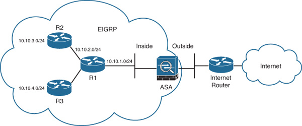
Complete the following steps to enable EIGRP in the Cisco ASA using ASDM:
1. Log in to ASDM and navigate to Configuration > Device Setup > Routing > EIGRP > Setup. The screen shown in Figure 12-30 is displayed.
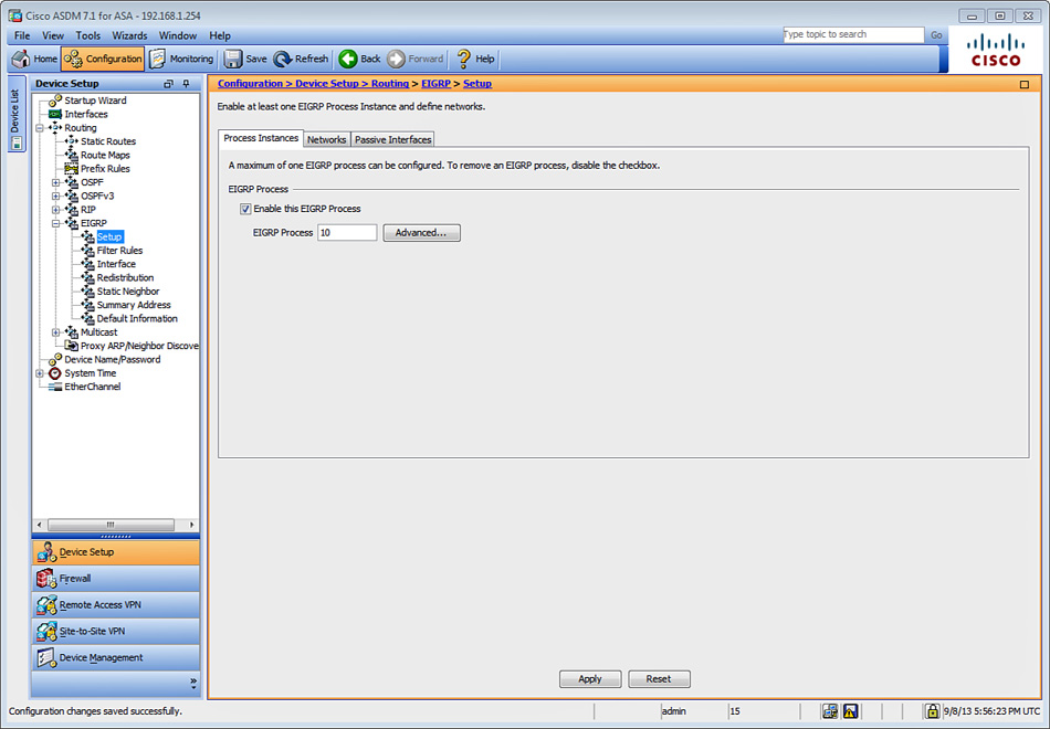
2. To enable EIGRP, check Enable This EIGRP Process in the EIGRP Process area.
3. Enter the EIGRP autonomous system (AS) number in the EIGRP Process field. For this example, use the number 10. This number must match in all EIGRP neighbors. The AS number can be any value from 1 to 65535.
4. (Optional) You can click the Advanced button to configure the following EIGRP advanced properties in the Edit EIGRP Process Advanced Properties dialog box, shown in Figure 12-31:
![]() Automatic route summarization
Automatic route summarization
![]() Router ID
Router ID
![]() Metric parameters
Metric parameters
![]() Stub configuration
Stub configuration
![]() Administrative distance
Administrative distance
In this example, automatic summarization is disabled; all other default values are used.
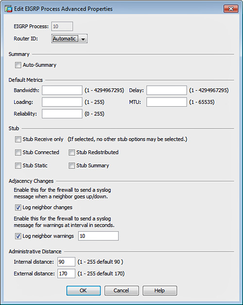
6. Click the Networks tab to configure the networks for the EIGRP process.
7. Click Add to add the EIGRP networks. The dialog box displayed in Figure 12-32 opens.

8. For the example topology shown in Figure 12-29, use the inside network 10.10.1.0 with netmask 255.255.255.0.
9. Click OK.
Note
The Passive Interface tab enables you to configure specific interfaces as passive interfaces. A passive interface does not send or receive routing updates. In Figure 12-32, no passive interfaces are designed.
10. Click Apply to apply the configuration changes.
11. Click Save to save the configuration in the Cisco ASA.
Alternatively, you can use the CLI to configure EIGRP. Example 12-33 shows the CLI commands sent by ASDM to the Cisco ASA.
Example 12-33 Enabling EIGRP via the CLI
router eigrp 10
no auto-summary
network 10.10.1.0 255.255.255.0
Use the router eigrp 10 command to enable EIGRP, using the AS number 10. The no auto-summary command disables automatic route summarization. The network command is used to configure all networks for the EIGRP process.
Example 12-34 shows the output of the show route inside command after the EIGRP routes have been learned from R1.
Example 12-34 Output of show route inside Showing EIGRP Routes
NewYork# show route inside
Codes: C - connected, S - static, I - IGRP, R - RIP, M - mobile, B - BGP
D - EIGRP, EX - EIGRP external, O - OSPF, IA - OSPF inter area
N1 - OSPF NSSA external type 1, N2 - OSPF NSSA external type 2
E1 - OSPF external type 1, E2 - OSPF external type 2, E - EGP
i - IS-IS, L1 - IS-IS level-1, L2 - IS-IS level-2, ia - IS-IS inter area
* - candidate default, U - per-user static route, o - ODR
P - periodic downloaded static route
Gateway of last resort is 209.165.201.2 to network 0.0.0.0
C 10.10.1.0 255.255.255.0 is directly connected, inside
D 10.10.2.0 255.255.255.0 [90/130816] via 10.10.1.2, 0:01:47, inside
D 10.10.3.0 255.255.255.0 [90/130816] via 10.10.1.2, 0:01:43, inside
D 10.10.4.0 255.255.255.0 [90/130816] via 10.10.1.2, 0:00:21, inside
In Example 12-34, three routes are learned for the internal networks via R1 (10.10.1.2). The letter D indicates that these routes are learned via EIGRP.
Configuring Route Filtering for EIGRP
The Cisco ASA supports EIGRP route filtering. You can filter routes learned via EIGRP or prevent specific routes from being advertised to EIGRP neighbors. The goal in the following example is to configure the Cisco ASA to filter the route to the network 10.10.4.0/24 learned from R1. To achieve this objective, complete the following steps:
1. Log in to ASDM and navigate to Configuration > Device Setup > Routing > EIGRP > Filter Rules.
2. Click Add to add a filter rule. The Add Filter Rules dialog box shown in the background in Figure 12-33 is displayed.
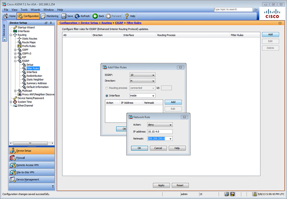
3. Choose the respective EIGRP AS from the EIGRP drop-down menu. In this example, the EIGRP AS number 10 is used.
4. In the Direction drop-down list, choose the direction in which the filter is to be applied. The filter is applied inbound (in) in Figure 12-33.
5. In the Interface drop-down list, choose the interface where the filter is to be applied. In Figure 12-33, the inside interface is specified.
6. Click Add to open the Network Rule dialog box, shown in the foreground in Figure 12-33, and enter the routes/networks to be allowed or denied. In this example, the action is set to deny incoming route advertisements for the 10.10.4.0/24 network.
7. Click OK.
8. Click Apply to apply the configuration changes.
9. Click Save to save the configuration in the Cisco ASA.
Example 12-35 shows the CLI commands sent by ASDM to the Cisco ASA for EIGRP route filtering.
Example 12-35 Configuring EIGRP Route Filtering via the CLI
access-list eigrpACL_FR standard deny 10.10.4.0 255.255.255.0
access-list eigrpACL_FR standard permit any
router eigrp 10
distribute-list eigrpACL_FR in interface inside
In Example 12-35, a standard ACL (eigrpACL_FR) is configured to deny the 10.10.4.0 network. This ACL is then applied inbound to the distribute-list command in the inside interface.
EIGRP Authentication
The Cisco ASA supports EIGRP authentication using MD5 hashing. Complete the following steps to enable EIGRP MD5 authentication:
1. Log in to ASDM and navigate to Configuration > Device Setup > Routing > EIGRP > Interface.
2. Select the interface where EIGRP MD5 authentication is to be enabled and click Edit. The Edit EIGRP Interface Entry dialog box shown in Figure 12-34 is displayed.
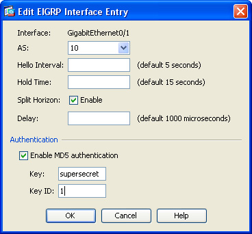
3. In the Authentication area, check Enable MD5 Authentication.
4. In the Key field, enter the key (password) to be used. The key supersecret is used (masked) in this example.
5. In the Key ID field, enter the key identifier The Key ID 1 is employed in Figure 12-34.
6. Click OK.
7. Click Apply to apply the configuration changes.
8. Click Save to save the configuration in the Cisco ASA.
Example 12-36 shows the CLI commands sent by ASDM to the Cisco ASA to enable EIGRP MD5 authentication.
Example 12-36 Configuring EIGRP MD5 Authentication Using the CLI
interface GigabitEthernet0/1
authentication key eigrp 10 supersecret key-id 1
authentication mode eigrp 10 md5
EIGRP authentication is enabled under the inside interface (GigabitEthernet0/1). The second line defines the key supersecret and key ID 1 for the EIGRP AS number 10. The third line enables MD5 authentication. The authentication key is removed and labeled as <removed> when you view the configuration, using the show running-config command or show configuration command.
Defining Static EIGRP Neighbors
The Cisco ASA supports statically defined EIGRP neighbors. Typically, EIGRP neighbors are dynamically discovered; however, on point-to-point, non-broadcast networks, you must statically define the neighbors.
Configure a static neighbor in the Cisco ASA by completing the following steps:
1. Log in to ASDM and navigate to Configuration > Device Setup > Routing > EIGRP > Static Neighbor.
2. Click Add to add a new EIGRP static neighbor.
3. Enter the EIGRP neighbor IP address in the Add EIGRP Neighbor Entry dialog box.
4. Click OK.
5. Click Apply to apply the configuration changes.
6. Click Save to save the configuration in the Cisco ASA.
Alternatively, in the CLI, you can use the neighbor command, as shown in Example 12-37.
Example 12-37 Configuring a Static EIGRP Neighbor
router eigrp 10
neighbor 10.10.1.2 interface inside
In Example 12-37, the neighbor 10.10.1.2 is statically defined.
Route Summarization in EIGRP
The Cisco ASA supports EIGRP route summarization. This is used to manually define summary addresses if you want to create summary addresses that do not occur at a network number boundary. In other words, if any specific routes are in the routing table, EIGRP advertises the summary address out the specified interface with a metric equal to the minimum of all the more specific routes.
EIGRP route summarization is configured on the Cisco ASA when automatic route summarization is disabled. Summary addresses are configured on the Cisco ASA on a per-interface basis.
Complete the following steps to create a summary address:
1. Log in to ASDM and navigate to Configuration > Device Setup > Routing > EIGRP > Summary Address.
2. Click Add to add a summary address entry. The dialog box shown in Figure 12-35 is displayed.
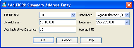
3. In the EIGRP AS drop-down list, choose the EIGRP AS where summarization is applied. The EIGRP AS used in this example is 10.
4. Enter the IP address and the netmask of the summary address in the respective fields. The 10.10.0.0 network address and 255.255.0.0 netmask are used. Subsequently, the 10.10.1.0/24, 10.10.2.0/24, 10.10.3.0/24, and 10.10.4.0/24 networks will be summarized as 10.10.0.0/16.
5. Enter the administrative distance used for this summary address. In this example, the administrative distance used is 10. The default is 5.
6. Click OK.
7. Click Apply to apply the configuration changes.
8. Click Save to save the configuration in the Cisco ASA.
Alternatively, you can use the summary-address interface subcommand to configure summarization under a specific interface. Example 12-38 shows the CLI commands sent by ASDM to the Cisco ASA.
Example 12-38 Configuring an EIGRP Summary Address
interface GigabitEthernet0/1
summary-address eigrp 10 10.10.0.0 255.255.0.0 10
In Example 12-38, the summary-address interface subcommand defines the summary address 10.10.0.0 with netmask 255.255.0.0 applied to the EIGRP AS number 10. The administrative distance is set to 10 at the end of the command.
Split Horizon
The Cisco ASA supports split horizon. Split horizon is enabled on all interfaces by default. When you configure split horizon, EIGRP update and query packets are not sent for destinations for which the specified interface is the next hop. This is used to minimize the potential of routing loops.
In some cases, such as non-broadcast networks, split horizon may not be necessary and may need to be disabled. You can disable split horizon with ASDM by completing the following steps:
1. Log in to ASDM and navigate to Configuration > Device Setup > Routing > EIGRP > Interface.
2. Select the respective interface and click Edit.
3. The Edit EIGRP Interface Entry dialog box is displayed. This dialog box was illustrated earlier in Figure 12-34. Uncheck the Enable box in the Split Horizon field.
4. Click OK.
5. Click Apply to apply the configuration changes.
6. Click Save to save the configuration in the Cisco ASA.
Alternatively, you can use the no split-horizon eigrp <as number> interface subcommand to disable split horizon on a specific interface.
Route Redistribution in EIGRP
As with RIP and OSPF, in EIGRP you can redistribute routes from other routing protocols. To configure route redistribution in ASDM, complete the following steps:
1. Log in to ASDM and navigate to Configuration > Device Setup > Routing > EIGRP > Redistribution.
2. Click Add to add an EIGRP redistribution entry. The dialog box shown in Figure 12-36 is displayed.
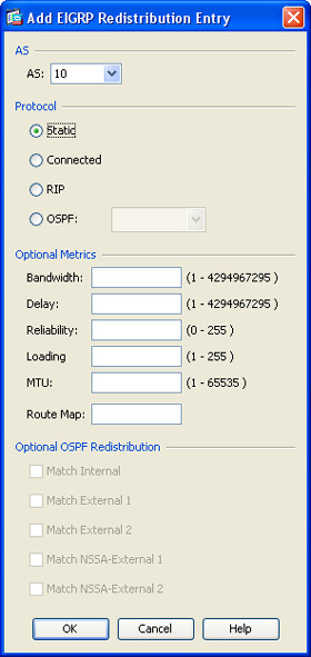
3. From the AS drop-down list, choose the AS number where route redistribution will be applied. In this example, the EIGRP AS number 10 is selected.
4. In the Protocol area, click the radio button corresponding to the protocol to be redistributed into EIGRP. For this example, static routes are redistributed into EIGRP, so the Static option is selected.
5. You can configure several optional metrics and EIGRP redistribution parameters. In Figure 12-36, the defaults are used. However, the following are all the supported advanced options:
![]() Bandwidth: Used to specify the EIGRP bandwidth metric in kilobits per second.
Bandwidth: Used to specify the EIGRP bandwidth metric in kilobits per second.
![]() Delay: Used to specify the EIGRP delay metric, in 10-microsecond units.
Delay: Used to specify the EIGRP delay metric, in 10-microsecond units.
![]() Reliability: Used to specify the EIGRP reliability metric.
Reliability: Used to specify the EIGRP reliability metric.
![]() Loading: Used to specify the EIGRP loading bandwidth metric.
Loading: Used to specify the EIGRP loading bandwidth metric.
![]() MTU: Used to specify the minimum MTU of the path.
MTU: Used to specify the minimum MTU of the path.
![]() Route Map: Used to granularly define which routes are redistributed into the EIGRP.
Route Map: Used to granularly define which routes are redistributed into the EIGRP.
You can also (optionally) specify which OSPF routes are redistributed into the EIGRP routing process by checking any of the following check boxes in the Optional OSPF Redistribution area:
![]() Match Internal: Used to match internal OSPF routes
Match Internal: Used to match internal OSPF routes
![]() Match External 1: Used to match external type 1 routes
Match External 1: Used to match external type 1 routes
![]() Match External 2: Used to match external type 2 routes
Match External 2: Used to match external type 2 routes
![]() Match NSSA-External 1: Used to match NSSA external type 1 routes
Match NSSA-External 1: Used to match NSSA external type 1 routes
![]() Match NSSA-External 2: Used to match NSSA external type 2 routes
Match NSSA-External 2: Used to match NSSA external type 2 routes
6. Click OK.
7. Click Apply to apply the configuration changes.
8. Click Save to save the configuration in the Cisco ASA.
Example 12-39 includes the commands sent by ASDM to the Cisco ASA.
Example 12-39 Redistributing Static Routes into EIGRP
router eigrp 10
redistribute static
In Example 12-39, the redistribute static command is used to redistribute static routes into the EIGRP process.
You can use the redistribute connected command to redistribute connected routes into the EIGRP routing process, as shown here:
redistribute connected [metric bandwidth delay reliability loading mtu] [route-map
map_name]
To redistribute routes from an OSPF routing process into the EIGRP routing process, use the redistribute ospf command as follows:
redistribute ospf pid [match { internal | external [1 | 2] | nssa-external [1 |
2]} ] [metric bandwidth delay reliability loading mtu] [route-map map_name]
To redistribute routes from a RIP routing process into the EIGRP routing process, use the redistribute rip command as follows:
redistribute rip [metric bandwidth delay reliability load mtu] [route-map map_
name]
Tip
The default-metric command in the EIGRP router configuration can be employed to specify default metric values to be used for all routes redistributed into EIGRP. On the other hand, you must specify the EIGRP metric values in the preceding redistribute commands if the default-metric command is not used.
Controlling Default Information
When EIGRP is enabled, default routes are sent and accepted in the Cisco ASA by default, which is a configurable behavior. To design a set of rules for controlling the sending and receiving of default route information in EIGRP updates, complete the following steps:
1. Log in to ASDM and navigate to Configuration > Device Setup > Routing > EIGRP > Default Information.
2. You can have one in rule and one out rule for each EIGRP routing process. However, only one process is currently supported. Here the goal is to deny any default route to be learned by the EIGRP process. Select the direction of the filter rule that reads in and click Edit. The Edit Default Information dialog box is displayed.
3. Select the EIGRP process.
4. Make sure that the Direction field is set to in.
5. Click Add to add the new rule. The Network Rule dialog box is displayed.
6. Choose deny from the Action drop-down menu.
7. Enter 0.0.0.0 in the IP Address field.
8. Enter 0.0.0.0 in the Netmask field.
9. Click OK in the Network Rule dialog box.
10. Click OK in the Add Default Information dialog box.
11. Click OK.
12. Click Apply to apply the configuration changes.
13. Click Save to save the configuration in the Cisco ASA.
Example 12-40 shows the CLI commands sent by ASDM to the Cisco ASA.
Example 12-40 Default Information Filtering in EIGRP
access-list eigrpACL_DI standard deny any
router eigrp 10
default-information in eigrpACL_DI
In Example 12-40, a standard ACL named eigrpACL_DI is configured denying any. Then the default-information router subcommand is used with the in keyword to deny the default routes inbound. The eigrpACL_DI ACL name is entered at the end of the default-information command. Alternatively, you can use the no default-information in command without the need of an access control list.
Troubleshooting EIGRP
This section covers detailed information for troubleshooting problems in EIGRP.
Useful Troubleshooting Commands
The show eigrp topology command is used to display the EIGRP topology in the Cisco ASA. Example 12-41 shows the output of this command.
Example 12-41 Displaying the EIGRP Topology
NewYork# show eigrp topology
EIGRP-IPv4 Topology Table for AS(10)/ID(209.165.201.1)
Codes: P - Passive, A - Active, U - Update, Q - Query, R - Reply,
r - reply Status, s - sia Status
P 10.10.1.0 255.255.255.0, 1 successors, FD is 2816
via Connected, GigabitEthernet0/1
P 10.10.2.0 255.255.255.0, 1 successors, FD is 130816
via 10.10.1.2 (130816/128256), GigabitEthernet0/1
P 10.10.3.0 255.255.255.0, 1 successors, FD is 130816
via 10.10.1.2 (130816/128256), GigabitEthernet0/1
P 10.10.4.0 255.255.255.0, 1 successors, FD is 130816
via 10.10.1.2 (130816/128256), GigabitEthernet0/1
In Example 12-41, the three routes learned from 10.10.1.2 are displayed.
Tip
By default only routes from feasible successors are displayed. However, you can use the all-links keyword to display all routes, including those that are not feasible successors.
The show eigrp neighbors command provides the details of current EIGRP neighbors. Example 12-42 shows the output of this command.
Example 12-42 Output of show eigrp neighbors Command
NewYork# show eigrp neighbors
EIGRP-IPv4 neighbors for process 10
H Address Interface Hold Uptime SRTT RTO Q Seq
(sec) (ms) Cnt Num
0 10.10.1.2 Gi0/1 12 00:03:06 1 200 0 6
In Example 12-42, the inside router (10.10.1.2) is displayed. You can also see the interface where the neighbor resides (Gi0/1). You can also see the Hold timer, which is the length of time (in seconds) that the Cisco ASA waits to receive a Hello packet from the neighbor routing device before declaring it down. If the Hold timer value reaches 0, the Cisco ASA marks the neighbor unreachable (down).
The Uptime value is the elapsed time since the Cisco ASA first heard from this neighbor. This is displayed in hours:minutes:seconds.
The smooth round-trip time (SRTT) is the number of milliseconds required for an EIGRP packet to be sent to this neighbor and for the Cisco ASA to receive a reply.
Retransmission timeout (RTO) is the amount of time the Cisco ASA waits before resending a hello packet to a neighbor. The Q Cnt is the number of EIGRP packets that are in queue to be sent by the Cisco ASA. The Seq Num is the sequence number of the last EIGRP packet received from the neighbor.
The show eigrp events command displays the EIGRP event log. This output is limited to 500 events. New events are added to the bottom of the output, and old events are removed from the top of the output. Example 12-43 shows the output of the show eigrp events command.
Example 12-43 Output of show eigrp events Command
NewYork# show eigrp events
Event information for AS 10: 1 18:53:31.353 Change queue emptied, entries: 3
2 18:53:31.353 Metric set: 10.10.4.0 255.255.255.0 130816
3 18:53:31.353 Update reason, delay: new if 4294967295
4 18:53:31.353 Update sent, RD: 10.10.4.0 255.255.255.0 4294967295
5 18:53:31.353 Update reason, delay: metric chg 4294967295
6 18:53:31.353 Update sent, RD: 10.10.4.0 255.255.255.0 4294967295
7 18:53:31.353 Route install: 10.10.4.0 255.255.255.0 10.10.1.2
8 18:53:31.353 Find FS: 10.10.4.0 255.255.255.0 4294967295
9 18:53:31.353 Rcv update met/succmet: 130816 128256
In Example 12-43, updates are sent and received from the neighbor router. The route to the network 10.10.4.0/24 is received and installed in the routing table.
Tip
You can use the clear eigrp events command to clear the EIGRP event log. Neighbor change, neighbor warning, and DUAL FSM messages are logged by default in the Cisco ASA. However, you can disable neighbor change event logging by using the no eigrp log-neighbor-changes command. You can disable neighbor warning event logging by employing the no eigrp log-neighbor-warnings command under the router eigrp process. On the other hand, you cannot disable the logging of DUAL FSM events.
Use the show eigrp interfaces command to display the interfaces where EIGRP is enabled. Example 12-44 shows the output of the show eigrp interfaces command.
Example 12-44 Output of show eigrp interfaces Command
NewYork# show eigrp interfaces
EIGRP-IPv4 interfaces for process 10
Xmit Queue Mean Pacing Time Multicast Pending
Interface Peers Un/Reliable SRTT Un/Reliable Flow Timer Routes
inside 1 0/0 1 0/1 50 0
In Example 12-44, EIGRP is enabled only on the inside interface and it currently has one peer.
Use the show eigrp traffic command to display EIGRP traffic statistics. Example 12-45 shows the output of the show eigrp traffic command.
Example 12-45 Output of show eigrp traffic Command
NewYork# show eigrp traffic
EIGRP-IPv4 Traffic Statistics for AS 10
Hellos sent/received: 5976/467
Updates sent/received: 3/8
Queries sent/received: 0/0
Replies sent/received: 0/0
Acks sent/received: 6/0
Input queue high water mark 1, 0 drops
SIA-Queries sent/received: 0/0
SIA-Replies sent/received: 0/0
Hello Process ID: 253
PDM Process ID: 252
As shown in Example 12-45, the show eigrp traffic command displays the number of EIGRP packets sent and received in the Cisco ASA. These packets include
![]() Hellos
Hellos
![]() Updates
Updates
![]() Queries
Queries
![]() Replies
Replies
![]() Acknowledgments
Acknowledgments
![]() Additional statistical information
Additional statistical information
The debug eigrp fsm command is one of the most useful debug commands used to troubleshoot EIGRP problems. Example 12-46 shows the output of the debug eigrp fsm command during normal operations.
Example 12-46 Output of debug eigrp fsm Command During Normal Operations
NewYork# debug eigrp fsm
EIGRP FSM Events/Actions debugging is on
DUAL: rcvupdate: 10.10.2.0 255.255.255.0 via 10.10.1.2 metric 130816/128256 on
topoid 0
DUAL: Find FS for dest 10.10.2.0 255.255.255.0. FD is 4294967295, RD is 4294967295
on topoid 0 found
EIGRP-IPv4(Default-IP-Routing-Table:10): route installed for 10.10.2.0 ()
DUAL: RT installed 10.10.2.0 255.255.255.0 via 10.10.1.2
DUAL: Send update about 10.10.2.0 255.255.255.0. Reason: metric chg on topoid 0
DUAL: Send update about 10.10.2.0 255.255.255.0. Reason: new if on topoid 0
DUAL: dest(10.10.3.0 255.255.255.0) not active
DUAL: rcvupdate: 10.10.3.0 255.255.255.0 via 10.10.1.2 metric 130816/128256 on
topoid 0
DUAL: Find FS for dest 10.10.3.0 255.255.255.0. FD is 4294967295, RD is 4294967295
on topoid 0 found
EIGRP-IPv4(Default-IP-Routing-Table:10): route installed for 10.10.3.0 ()
DUAL: RT installed 10.10.3.0 255.255.255.0 via 10.10.1.2
DUAL: Send update about 10.10.3.0 255.255.255.0. Reason: metric chg on topoid 0
DUAL: Send update about 10.10.3.0 255.255.255.0. Reason: new if on topoid 0
DUAL: dest(10.10.4.0 255.255.255.0) not active
DUAL: rcvupdate: 10.10.4.0 255.255.255.0 via 10.10.1.2 metric 130816/128256 on
topoid 0
DUAL: Find FS for dest 10.10.4.0 255.255.255.0. FD is 4294967295, RD is 4294967295
on topoid 0 found
EIGRP-IPv4(Default-IP-Routing-Table:10): route installed for 10.10.4.0 ()
DUAL: RT installed 10.10.4.0 255.255.255.0 via 10.10.1.2
DUAL: Send update about 10.10.4.0 255.255.255.0. Reason: metric chg on topoid 0
DUAL: Send update about 10.10.4.0 255.255.255.0. Reason: new if on topoid 0
In Example 12-46, the updates are received from the EIGRP neighbor 10.10.1.2 and the routes received are installed on the routing table.
Stability and failure in the EIGRP neighbor relationship are some of the most common issues. The following are some of the reasons why EIGRP neighbors may fail (flap):
![]() Underlying link flaps.
Underlying link flaps.
![]() Misconfigured Hello and Hold intervals.
Misconfigured Hello and Hold intervals.
![]() Loss of hello packets.
Loss of hello packets.
![]() Existence of unidirectional links.
Existence of unidirectional links.
![]() Route goes stuck-in-active. When a router enters the stuck-in-active state, the neighbors from which the reply was expected are reinitialized, and the router goes active on all routes learned from those neighbors and is able to process all routing updates.
Route goes stuck-in-active. When a router enters the stuck-in-active state, the neighbors from which the reply was expected are reinitialized, and the router goes active on all routes learned from those neighbors and is able to process all routing updates.
![]() Provision of insufficient bandwidth for the EIGRP process and improperly set bandwidth statements.
Provision of insufficient bandwidth for the EIGRP process and improperly set bandwidth statements.
![]() One-way multicast traffic.
One-way multicast traffic.
![]() Query storms.
Query storms.
![]() Authentication problems.
Authentication problems.
The following sections cover some common scenarios encountered while troubleshooting EIGRP issues.
Scenario 1: Link Failures
When an interface goes down, EIGRP disables the neighbors that are reachable through that interface and flushes all routes learned through that neighbor. The debug eigrp fsm command is very useful while troubleshooting these kinds of problems. In Example 12-47, the link between the Cisco ASA and the inside router (10.10.1.2) failed. It shows the output of the debug eigrp fsm when the link went down.
Example 12-47 Output of debug eigrp fsm Command During a Link Failure
NewYork# debug eigrp fsm
EIGRP FSM Events/Actions debugging is on
NewYork# IGRP2: linkdown: start - 10.10.1.2 via GigabitEthernet0/1
DUAL: Destination 10.10.1.0 255.255.255.0 for topoid 0
DUAL: Destination 10.10.2.0 255.255.255.0 for topoid 0
DUAL: Find FS for dest 10.10.2.0 255.255.255.0. FD is 130816, RD is 130816 on
topoid 0
DUAL: 10.10.1.2 metric 4294967295/4294967295
not found Dmin is 4294967295
DUAL: Peer total 0 stub 0 template 0 for topoid 0
DUAL: Dest 10.10.2.0 255.255.255.0 (No peers) not entering active state for
topoid 0.DUAL: Removing dest 10.10.2.0 255.255.255.0, nexthop 10.10.1.2
DUAL: No routes. Flushing dest 10.10.2.0 255.255.255.0
DUAL: Destination 10.10.3.0 255.255.255.0 for topoid 0
DUAL: Find FS for dest 10.10.3.0 255.255.255.0. FD is 130816, RD is 130816 on
topoid 0
DUAL: 10.10.1.2 metric 4294967295/4294967295
not found Dmin is 4294967295
DUAL: Peer total 0 stub 0 template 0 for topoid
DUAL: Dest 10.10.3.0 255.255.255.0 (No peers) not entering active state for
topoid 0.DUAL: Removing dest 10.10.3.0 255.255.255.0, nexthop 10.10.1.2
DUAL: No routes. Flushing dest 10.10.3.0 255.255.255.0
DUAL: Destination 10.10.4.0 255.255.255.0 for topoid 0
DUAL: Find FS for dest 10.10.4.0 255.255.255.0. FD is 130816, RD is 130816 on
topoid 0
DUAL: 10.10.1.2 metric 4294967295/4294967295
not found Dmin is 4294967295
DUAL: Peer total 0 stub 0 template 0 for topoid 0
DUAL: Dest 10.10.4.0 255.255.255.0 (No peers) not entering active state for
topoid 0.DUAL: Removing dest 10.10.4.0 255.255.255.0, nexthop 10.10.1.2
DUAL: No routes. Flushing dest 10.10.4.0 255.255.255.0
DUAL: linkdown: finish
In Example 12-47, the Cisco ASA detected that the link was down and removed all the entries for the routes learned from the neighbor (10.10.1.2).
Scenario 2: Misconfigured Hello and Hold Intervals
In the Cisco ASA and Cisco IOS routers, the EIGRP hold interval can be set independently of the hello interval. This is done with the hold-time eigrp interface subcommand. If you set a hold interval smaller than the hello interval, it results in the neighbors flapping continuously. Therefore, it is recommended that the hold time be at least three times the hello interval.
In Example 12-48, the Hold interval was set to 2 seconds on the neighbor router (10.10.1.2). It shows the output of the debug eigrp fsm while the neighbor relationship between the Cisco ASA and the inside router was flapping continuously.
Example 12-48 Output of debug eigrp fsm Command While Neighbors Are Flapping
DUAL: rcvupdate: 10.10.2.0 255.255.255.0 via 10.10.1.2 metric 130816/128256 on
topoid 0
DUAL: Find FS for dest 10.10.2.0 255.255.255.0. FD is 4294967295, RD is 4294967295
on topoid 0 found
EIGRP-IPv4(Default-IP-Routing-Table:10): route installed for 10.10.2.0 ()
DUAL: RT installed 10.10.2.0 255.255.255.0 via 10.10.1.2
DUAL: Send update about 10.10.2.0 255.255.255.0. Reason: metric chg on topoid 0
DUAL: Send update about 10.10.2.0 255.255.255.0. Reason: new if on topoid 0
DUAL: dest(10.10.3.0 255.255.255.0) not active
DUAL: rcvupdate: 10.10.3.0 255.255.255.0 via 10.10.1.2 metric 130816/128256 on
topoid 0
DUAL: Find FS for dest 10.10.3.0 255.255.255.0. FD is 4294967295, RD is 4294967295
on topoid 0
EIGRP-IPv4(Default-IP-Routing-Table:10): route installed for 10.10.3.0 ()
DUAL: RT installed 10.10.3.0 255.255.255.0 via 10.10.1.2
DUAL: Send update about 10.10.3.0 255.255.255.0. Reason: metric chg on topoid 0
DUAL: Send update about 10.10.3.0 255.255.255.0. Reason: new if on topoid 0
DUAL: dest(10.10.4.0 255.255.255.0) not active
DUAL: rcvupdate: 10.10.4.0 255.255.255.0 via 10.10.1.2 metric 130816/128256 on
topoid 0
DUAL: Find FS for dest 10.10.4.0 255.255.255.0. FD is 4294967295, RD is 4294967295
on topoid 0 found
EIGRP-IPv4(Default-IP-Routing-Table:10): route installed for 10.10.4.0 ()
DUAL: RT installed 10.10.4.0 255.255.255.0 via 10.10.1.2
DUAL: Send update about 10.10.4.0 255.255.255.0. Reason: metric chg on topoid 0
DUAL: Send update about 10.10.4.0 255.255.255.0. Reason: new if on topoid 0
IGRP2: linkdown: start - 10.10.1.2 via GigabitEthernet0/1
DUAL: Destination 10.10.1.0 255.255.255.0 for topoid 0
DUAL: Destination 10.10.2.0 255.255.255.0 for topoid 0
DUAL: Find FS for dest 10.10.2.0 255.255.255.0. FD is 130816, RD is 130816 on topoid 0
DUAL: 10.10.1.2 metric 4294967295/4294967295
not found Dmin is 4294967295
DUAL: Peer total 0 stub 0 template 0 for topoid 0
DUAL: Dest 10.10.2.0 255.255.255.0 (No peers) not entering active state for
topoid 0.DUAL: Removing dest 10.10.2.0 255.255.255.0, nexthop 10.10.1.2
DUAL: No routes. Flushing dest 10.10.2.0 255.255.255.0
DUAL: Destination 10.10.3.0 255.255.255.0 for topoid 0
DUAL: Find FS for dest 10.10.3.0 255.255.255.0. FD is 130816, RD is 130816 on topoid 0
DUAL: 10.10.1.2 metric 4294967295/4294967295
not found Dmin is 4294967295
DUAL: Peer total 0 stub 0 template 0 for topoid 0
DUAL: Dest 10.10.3.0 255.255.255.0 (No peers) not entering active state for
topoid 0.DUAL: Removing dest 10.10.3.0 255.255.255.0, nexthop 10.10.1.2
DUAL: No routes. Flushing dest 10.10.3.0 255.255.255.0
DUAL: Destination 10.10.4.0 255.255.255.0 for topoid 0
DUAL: Find FS for dest 10.10.4.0 255.255.255.0. FD is 130816, RD is 130816 on topoid 0
DUAL: 10.10.1.2 metric 4294967295/4294967295
not found Dmin is 4294967295
DUAL: Peer total 0 stub 0 template 0 for topoid
DUAL: Dest 10.10.4.0 255.255.255.0 (No peers) not entering active state for
topoid 0.DUAL: Removing dest 10.10.4.0 255.255.255.0, nexthop 10.10.1.2
DUAL: No routes. Flushing dest 10.10.4.0 255.255.255.0
DUAL: linkdown: finish
DUAL: dest(10.10.2.0 255.255.255.0) not active
DUAL: rcvupdate: 10.10.2.0 255.255.255.0 via 10.10.1.2 metric 130816/128256 on topoid 0
DUAL: Find FS for dest 10.10.2.0 255.255.255.0. FD is 4294967295, RD is 4294967295 on
topoid 0 found
EIGRP-IPv4(Default-IP-Routing-Table:10): route installed for 10.10.2.0 ()
DUAL: RT installed 10.10.2.0 255.255.255.0 via 10.10.1.2
DUAL: Send update about 10.10.2.0 255.255.255.0. Reason: metric chg on topoid 0
DUAL: Send update about 10.10.2.0 255.255.255.0. Reason: new if on topoid 0
DUAL: dest(10.10.3.0 255.255.255.0) not active
DUAL: rcvupdate: 10.10.3.0 255.255.255.0 via 10.10.1.2 metric 130816/128256 on topoid 0
...
<output truncated>
The output of Example 12-48 is truncated; however, you can see the neighbor relationship between the Cisco ASA and the inside router flapping continuously. Routes first are learned and then removed.
The output of the show eigrp events command also displays the neighbor relationship flapping. One of the advantages of show eigrp events is that it includes a timestamp at the beginning of each log entry. Example 12-49 includes the output of the show eigrp events command while the neighbors were flapping.
Example 12-49 Output of show eigrp events Command While Neighbors Are Flapping
NewYork# show eigrp events
Event information for AS 10: 1 15:55:59.882 Change queue emptied, entries: 3
2 15:55:59.882 Metric set: 10.10.4.0 255.255.255.0 130816
3 15:55:59.882 Update reason, delay: new if 4294967295
4 15:55:59.882 Update sent, RD: 10.10.4.0 255.255.255.0 4294967295
5 15:55:59.882 Update reason, delay: metric chg 4294967295
6 15:55:59.882 Update sent, RD: 10.10.4.0 255.255.255.0 4294967295
7 15:55:59.882 Route install: 10.10.4.0 255.255.255.0 10.10.1.2
8 15:55:59.882 Find FS: 10.10.4.0 255.255.255.0 4294967295
9 15:55:59.882 Rcv update met/succmet: 130816 128256
10 15:55:59.882 Rcv update dest/nh: 10.10.4.0 255.255.255.0 10.10.1.2
11 15:55:59.882 Metric set: 10.10.4.0 255.255.255.0 4294967295
12 15:55:59.882 Metric set: 10.10.3.0 255.255.255.0 130816
13 15:55:59.882 Update reason, delay: new if 4294967295
14 15:55:59.882 Update sent, RD: 10.10.3.0 255.255.255.0 4294967295
15 15:55:59.882 Update reason, delay: metric chg 4294967295
16 15:55:59.882 Update sent, RD: 10.10.3.0 255.255.255.0 4294967295
17 15:55:59.882 Route install: 10.10.3.0 255.255.255.0 10.10.1.2
18 15:55:59.882 Find FS: 10.10.3.0 255.255.255.0 4294967295
19 15:55:59.882 Rcv update met/succmet: 130816 128256
20 15:55:59.882 Rcv update dest/nh: 10.10.3.0 255.255.255.0 10.10.1.2
21 15:55:59.882 Metric set: 10.10.3.0 255.255.255.0 4294967295
22 15:55:59.882 Metric set: 10.10.2.0 255.255.255.0 130816
23 15:55:59.882 Update reason, delay: new if 4294967295
24 15:55:59.882 Update sent, RD: 10.10.2.0 255.255.255.0 4294967295
25 15:55:59.882 Update reason, delay: metric chg 4294967295
26 15:55:59.882 Update sent, RD: 10.10.2.0 255.255.255.0 4294967295
27 15:55:59.882 Route install: 10.10.2.0 255.255.255.0 10.10.1.2
28 15:55:59.882 Find FS: 10.10.2.0 255.255.255.0 4294967295
29 15:55:59.882 Rcv update met/succmet: 130816 128256
30 15:55:59.882 Rcv update dest/nh: 10.10.2.0 255.255.255.0 10.10.1.2
31 15:55:59.882 Metric set: 10.10.2.0 255.255.255.0 4294967295
32 15:55:59.882 Rcv peer INIT: 10.10.1.2 GigabitEthernet0/1
33 15:55:57.572 NDB delete: 10.10.4.0 255.255.255.0 1
34 15:55:57.572 Poison squashed: 10.10.4.0 255.255.255.0 rt gone
35 15:55:57.572 RDB delete: 10.10.4.0 255.255.255.0 10.10.1.2
36 15:55:57.572 Not active net/1=SH: 10.10.4.0 255.255.255.0 0
37 15:55:57.572 FC not sat Dmin/met: 4294967295 130816
38 15:55:57.572 Find FS: 10.10.4.0 255.255.255.0 130816
39 15:55:57.572 NDB delete: 10.10.3.0 255.255.255.0 1
40 15:55:57.572 Poison squashed: 10.10.3.0 255.255.255.0 rt gone
41 15:55:57.572 RDB delete: 10.10.3.0 255.255.255.0 10.10.1.2
42 15:55:57.572 Not active net/1=SH: 10.10.3.0 255.255.255.0 0
43 15:55:57.572 FC not sat Dmin/met: 4294967295 130816
44 15:55:57.572 Find FS: 10.10.3.0 255.255.255.0 130816
45 15:55:57.572 NDB delete: 10.10.2.0 255.255.255.0 1
46 15:55:57.572 Poison squashed: 10.10.2.0 255.255.255.0 rt gone
47 15:55:57.572 RDB delete: 10.10.2.0 255.255.255.0 10.10.1.2
48 15:55:57.572 Not active net/1=SH: 10.10.2.0 255.255.255.0 0
The output shown in Example 12-49 is truncated; however, you can see the number of times the neighbor relationship flapped. Note the events in the highlighted lines are repeated within the command output.
Scenario 3: Misconfigured Authentication Parameters
In this scenario, authentication was configured in the Cisco ASA but was not configured in the inside router (10.10.1.2). The debug eigrp fsm is not useful for authentication problems. The debug eigrp packets can be used to show the transactions between the Cisco ASA and the inside router. Example 12-50 shows the output of the debug eigrp packets.
Example 12-50 Output of debug eigrp packets Command During EIGRP Authentication Failures
NewYork# debug eigrp packets
EIGRP Packets debugging is on
(UPDATE, REQUEST, QUERY, REPLY, HELLO, PROBE, ACK, STUB, SIAQUERY, SIAREPLY)
EIGRP: Sending HELLO on GigabitEthernet0/1
AS 655362, Flags 0x0, Seq 0/0 interfaceQ 255/254 iidbQ un/rely 0/0
EIGRP: GigabitEthernet0/1: ignored packet from 10.10.1.2, opcode = 5 (missing
authentication)
In Example 12-50, notice the Cisco ASA sending an EIGRP hello packet on the interface GigabitEthernet0/1 and then ignoring a packet received from 10.10.1.2 because it was not an authenticated packet (missing authentication).
Summary
This chapter covered the different routing protocols supported by Cisco ASA. Configuration examples included information on how to add a static route and configure dynamic routing protocols such as RIP, OSPF, and EIGRP, using ASDM and the CLI. Detailed sample configurations were provided, as well as tips on how to troubleshoot common problems when deploying these dynamic routing protocols.